User Manual
Page 8
... Interference Statement iv WEEE (Waste Electrical and Electronic Equipment) Statement v Chapter 1 Getting Started 1-1 Mainboard Specifications 1-2 Mainboard Layout 1-4 Packing Checklist 1-5 Chapter 2 Hardware Setup 2-1 Quick Components Guide 2-2 CPU (Central Processing Unit 2-3 Memory 2-6 Power Supply 2-8 Back Panel 2-9 Connectors 2-11 Jumpers 2-19 Switch 2-20 Slots 2-21 LED Status Indicators 2-25 Chapter 3 BIOS Setup 3-1 Entering Setup...
... Interference Statement iv WEEE (Waste Electrical and Electronic Equipment) Statement v Chapter 1 Getting Started 1-1 Mainboard Specifications 1-2 Mainboard Layout 1-4 Packing Checklist 1-5 Chapter 2 Hardware Setup 2-1 Quick Components Guide 2-2 CPU (Central Processing Unit 2-3 Memory 2-6 Power Supply 2-8 Back Panel 2-9 Connectors 2-11 Jumpers 2-19 Switch 2-20 Slots 2-21 LED Status Indicators 2-25 Chapter 3 BIOS Setup 3-1 Entering Setup...
User Manual
Page 11
...174; 64 bits PhenomTM II X3/ X4 & AthlonTM II X2/ X3/ X4 processors in the AM3 package. (For the latest information about CPU, please visit http://www.msi.com/index. php?func=cpuform2) HyperTransport ■ HyperTransport™ 3.0, supports up to 2.6 GHz Chipset ■ NVIDIA® nForce 980A SLI ...1066/ 800 SDRAM (total 16 GB Max) ■ 4 DDR3 DIMMs (240-pin/ 1.5V) *(For more information on compatible components, please visit http://www.msi.com/index.php?func=testreport) LAN ■ Supports Gb LAN (10/100/1000) Realtek® RTL8211CL 1394 (optional) ■ Chip integrated by VIA®...
...174; 64 bits PhenomTM II X3/ X4 & AthlonTM II X2/ X3/ X4 processors in the AM3 package. (For the latest information about CPU, please visit http://www.msi.com/index. php?func=cpuform2) HyperTransport ■ HyperTransport™ 3.0, supports up to 2.6 GHz Chipset ■ NVIDIA® nForce 980A SLI ...1066/ 800 SDRAM (total 16 GB Max) ■ 4 DDR3 DIMMs (240-pin/ 1.5V) *(For more information on compatible components, please visit http://www.msi.com/index.php?func=testreport) LAN ■ Supports Gb LAN (10/100/1000) Realtek® RTL8211CL 1394 (optional) ■ Chip integrated by VIA®...

User Manual
Page 17
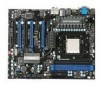
▍ Hardware Setup Quick Components Guide SYSFAN1, p.2-13 CPUFAN1, p.2-13 PWR1, p.2-8 CPU, p.2-3 DDR3, p.2-6 SYSFAN3, p.2-13 Back Panel, p.2-9 IDE1, p.2-11 ATX1, p.2-8 JCI1, p.2-12 PCIE, p.2-21 PCI, p.2-21 JAUD1, p.2-15 JCD1, p.2-13 OCSWITCH1, p.2-20 FDD1, p.2-11 JLPT1, p.2-16 JCOM1, p.2-16 JSPI, p.2-14 JBAT1, p.2-19 SYSFAN2, p.2-13 JTPM1, p.2-18 SATA, p.2-12 J1394_1, p.2-17 JFP2/ JFP1, p.2-14 JUSB1~4, p.2-15 2-2
▍ Hardware Setup Quick Components Guide SYSFAN1, p.2-13 CPUFAN1, p.2-13 PWR1, p.2-8 CPU, p.2-3 DDR3, p.2-6 SYSFAN3, p.2-13 Back Panel, p.2-9 IDE1, p.2-11 ATX1, p.2-8 JCI1, p.2-12 PCIE, p.2-21 PCI, p.2-21 JAUD1, p.2-15 JCD1, p.2-13 OCSWITCH1, p.2-20 FDD1, p.2-11 JLPT1, p.2-16 JCOM1, p.2-16 JSPI, p.2-14 JBAT1, p.2-19 SYSFAN2, p.2-13 JTPM1, p.2-18 SATA, p.2-12 J1394_1, p.2-17 JFP2/ JFP1, p.2-14 JUSB1~4, p.2-15 2-2
User Manual
Page 18
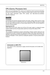
...the computer. For the latest information about CPU, please visit http://www.msi.com/index. We do not have the CPU cooler, consult your components are installing the CPU, make sure the cooling fan can work properly to protect the CPU from the grounded outlet first to ensure ...operate beyond product specifications. Gold arrow 2-3 Introduction to AM3 CPU The surface of thermal paste (or thermal tape) between the CPU and the heatsink to prevent overheating. Replacing the CPU While replacing the CPU, always turn off the ATX power supply or unplug the power supply's power cord from...
...the computer. For the latest information about CPU, please visit http://www.msi.com/index. We do not have the CPU cooler, consult your components are installing the CPU, make sure the cooling fan can work properly to protect the CPU from the grounded outlet first to ensure ...operate beyond product specifications. Gold arrow 2-3 Introduction to AM3 CPU The surface of thermal paste (or thermal tape) between the CPU and the heatsink to prevent overheating. Replacing the CPU While replacing the CPU, always turn off the ATX power supply or unplug the power supply's power cord from...
User Manual
Page 19
... close the lever. Meanwhile, do not forget to a 90-degree angle. 2. Make sure to raise the lever up to apply some thermal paste on CPU before installing the heat sink/cooler fan for the gold arrow of the correct installation procedures may cause permanent damages to make sure the... CPU has a cooler attached on the top to install the CPU & cooler correctly. The gold arrow should be seen. Wrong installation will cause the damage of your fingers pressing ...
... close the lever. Meanwhile, do not forget to a 90-degree angle. 2. Make sure to raise the lever up to apply some thermal paste on CPU before installing the heat sink/cooler fan for the gold arrow of the correct installation procedures may cause permanent damages to make sure the... CPU has a cooler attached on the top to install the CPU & cooler correctly. The gold arrow should be seen. Wrong installation will cause the damage of your fingers pressing ...
User Manual
Page 20
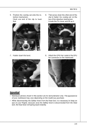
... your mainboard may vary depending on the model you purchase. • While disconnecting the Safety Hook from the fixed bolt, it . 7. Attach the CPU Fan cable to the CPU fan connector on the top of the clip to hook first. 6. Locate the Fix Lever and lift up it is necessary to keep...
... your mainboard may vary depending on the model you purchase. • While disconnecting the Safety Hook from the fixed bolt, it . 7. Attach the CPU Fan cable to the CPU fan connector on the top of the clip to hook first. 6. Locate the Fix Lever and lift up it is necessary to keep...

User Manual
Page 23
....r7+do.5uG8Vn.rP9do.Wu51nV0R1d.S1+O1B.1+K2211.V+3213.V+4.133.-5V.113.2G6V1V.rP7o1.SuG81-n.rO9Gdo2.NurG0o2n#.ruR1do2n.eu+2ds2n5.+3dV2.5+4V5.GVround ATX 8-pin CPU Power Connector: PWR1 This connector provides 12V power output to the CPUs. 1.G2.rG3o.urG4on.urdGonurdonudnd 5.+61.+721.V+821.V+21V2V Important... • Make sure that all the connectors are connected to proper ATX power supplies to connect an ATX 24-pin power supply. If you'd like ....
....r7+do.5uG8Vn.rP9do.Wu51nV0R1d.S1+O1B.1+K2211.V+3213.V+4.133.-5V.113.2G6V1V.rP7o1.SuG81-n.rO9Gdo2.NurG0o2n#.ruR1do2n.eu+2ds2n5.+3dV2.5+4V5.GVround ATX 8-pin CPU Power Connector: PWR1 This connector provides 12V power output to the CPUs. 1.G2.rG3o.urG4on.urdGonurdonudnd 5.+61.+721.V+821.V+21V2V Important... • Make sure that all the connectors are connected to proper ATX power supplies to connect an ATX 24-pin power supply. If you'd like ....
User Manual
Page 28
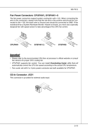
... to GND. CPUFAN1 4.3C.oS2n.e+1tnr.1osG2lorVround SYSFAN1/ 2 3.S2.e+1n1.sG2orVround SYSFAN3 3.N2.o+1U1.G2srVeound Important • Please refer to the recommended CPU fans at processor's official website or consult the vendors for external audio input. 4.R3.G2.rG1o.urLonudnd 2-13 MS-7612 Fan Power Connectors: CPUFAN1,... 4 pins power connector are both available for CPUFAN1. When connecting the wire to the connectors, always note that will automatically control the CPU fan speed according to the +12V; the black wire is the positive and should be connected to the actual...
... to GND. CPUFAN1 4.3C.oS2n.e+1tnr.1osG2lorVround SYSFAN1/ 2 3.S2.e+1n1.sG2orVround SYSFAN3 3.N2.o+1U1.G2srVeound Important • Please refer to the recommended CPU fans at processor's official website or consult the vendors for external audio input. 4.R3.G2.rG1o.urLonudnd 2-13 MS-7612 Fan Power Connectors: CPUFAN1,... 4 pins power connector are both available for CPUFAN1. When connecting the wire to the connectors, always note that will automatically control the CPU fan speed according to the +12V; the black wire is the positive and should be connected to the actual...

User Manual
Page 40
LED Status Indicators MS-7612 CPU Phase LEDs: LED1, LED2, LED3, LED4 These LEDs indicate the current CPU power phase mode. Blue light Off LED1 LED2 LED3 LED4 Mode CPU is in 1 phase power mode. Follow the instructions below to read. CPU is in 2 phase power mode. CPU is in 3 phase power mode. CPU is in 4 phase power mode. 2-25
LED Status Indicators MS-7612 CPU Phase LEDs: LED1, LED2, LED3, LED4 These LEDs indicate the current CPU power phase mode. Blue light Off LED1 LED2 LED3 LED4 Mode CPU is in 1 phase power mode. Follow the instructions below to read. CPU is in 2 phase power mode. CPU is in 3 phase power mode. CPU is in 4 phase power mode. 2-25

User Manual
Page 49
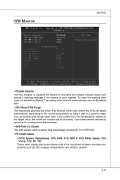
This sub-menu shows the CPU information, BIOS version and memory status of your system (read only). 3-8 ▍ BIOS Setup ▶ Hold on The setting determines whether the system will halt on for any detected error. ▶ System Information Press to enter the sub-menu, and the following screen appears. When the system stops for the errors preset, it will stop for 15 seconds and then automatically resume its operation. [All Error] The system stops when any error is detected. [No Error] The system does not stop if an error is detected at boot.
This sub-menu shows the CPU information, BIOS version and memory status of your system (read only). 3-8 ▍ BIOS Setup ▶ Hold on The setting determines whether the system will halt on for any detected error. ▶ System Information Press to enter the sub-menu, and the following screen appears. When the system stops for the errors preset, it will stop for 15 seconds and then automatically resume its operation. [All Error] The system stops when any error is detected. [No Error] The system does not stop if an error is detected at boot.
User Manual
Page 51
To find out which version to run in APIC mode. Due to compliance with the means to get to read the CPU power consumption while idle. You can to enable it via the various ACPI methods. 3-10 For better PCI performance, you should set to higher values, ... bus before another takes over. You need to enable or disable the APIC (Advanced Programmable Interrupt Controller). When set the item to higher values. ▶ CPU Feature Press to enter the sub-menu and the following screen appears: ▶ HPET The HPET (High Precision Event Timers) is a component that is part...
To find out which version to run in APIC mode. Due to compliance with the means to get to read the CPU power consumption while idle. You can to enable it via the various ACPI methods. 3-10 For better PCI performance, you should set to higher values, ... bus before another takes over. You need to enable or disable the APIC (Advanced Programmable Interrupt Controller). When set the item to higher values. ▶ CPU Feature Press to enter the sub-menu and the following screen appears: ▶ HPET The HPET (High Precision Event Timers) is a component that is part...

User Manual
Page 55
... powered while most other hardware components turn off to activate the ACPI (Advanced Configuration and Power Management Interface) Function. If your operating system is lost (CPU or chipset) and hardware maintains all sys-
... powered while most other hardware components turn off to activate the ACPI (Advanced Configuration and Power Management Interface) Function. If your operating system is lost (CPU or chipset) and hardware maintains all sys-
User Manual
Page 58
...fans' speeds. 3-17 It provides several sections to speed up for the SYSFAN1. ▶ PC Health Status ▶ CPU/ System Temperature, CPU FAN/ SYS FAN 1/ SYS FAN2 Speed, CPU Vcore, 3.3V, 5V, 12V These items display the current status of all of speed for cooling down automatically. ▶...FAN 1/ 2 Control This item allows users to the target value, the smart fan function will automatically return to [Enabled] later. ▶ CPU Smart FAN Target The mainboard provides the Smart Fan function which can enable a fan target value here. The setting of recording the chassis intrusion ...
...fans' speeds. 3-17 It provides several sections to speed up for the SYSFAN1. ▶ PC Health Status ▶ CPU/ System Temperature, CPU FAN/ SYS FAN 1/ SYS FAN2 Speed, CPU Vcore, 3.3V, 5V, 12V These items display the current status of all of speed for cooling down automatically. ▶...FAN 1/ 2 Control This item allows users to the target value, the smart fan function will automatically return to [Enabled] later. ▶ CPU Smart FAN Target The mainboard provides the Smart Fan function which can enable a fan target value here. The setting of recording the chassis intrusion ...
User Manual
Page 59
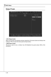
▍ BIOS Setup Green Power ▶ CPU Phase Control When set to [Auto], the hardware will auto adjust the CPU power phase according to the loading of CPU to reach the best power saving function. ▶ LED Power Control This item is used to turn on (Auto)/ turn off (Disabled) the power phase LEDs of the mainboard. 3-18
▍ BIOS Setup Green Power ▶ CPU Phase Control When set to [Auto], the hardware will auto adjust the CPU power phase according to the loading of CPU to reach the best power saving function. ▶ LED Power Control This item is used to turn on (Auto)/ turn off (Disabled) the power phase LEDs of the mainboard. 3-18

User Manual
Page 61
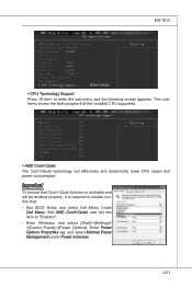
▍ BIOS Setup Cell Menu Important Change these settings only if you are familiar with the chipset. ▶ Current CPU / DRAM Frequency These items show the current clocks of installed CPU. 3-20 This submenu shows the information of CPU and Memory speed. Read-only. ▶ CPU Specifications Press to enter the sub-menu and the following screen appears.
▍ BIOS Setup Cell Menu Important Change these settings only if you are familiar with the chipset. ▶ Current CPU / DRAM Frequency These items show the current clocks of installed CPU. 3-20 This submenu shows the information of CPU and Memory speed. Read-only. ▶ CPU Specifications Press to enter the sub-menu and the following screen appears.
User Manual
Page 62
.... 3-21 Under Cell Menu, find AMD Cool'n'Quiet, and set this item to double confirm that the installed CPU supported. ▶ AMD Cool'n'Quiet The Cool'n'Quiet technology can effectively and dynamically lower CPU speed and power consumption. This submenu shows the technologies that : • Run BIOS Setup, and select Cell Menu...
.... 3-21 Under Cell Menu, find AMD Cool'n'Quiet, and set this item to double confirm that the installed CPU supported. ▶ AMD Cool'n'Quiet The Cool'n'Quiet technology can effectively and dynamically lower CPU speed and power consumption. This submenu shows the technologies that : • Run BIOS Setup, and select Cell Menu...

User Manual
Page 63
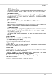
... DRAM Drive Strength This item allows you to adjust CPU clock multiplier (ratio). Read-only. ▶ Adjust CPU-NB Ratio This item is available only when the processor supports this function. ▶ Adjusted CPU Frequency (MHz) It shows the adjusted CPU frequency. This submenu displays the information of installed memory... Press to enter the sub-menu and the following screen appears. ▶ DIMM1~4 Memory SPD Information Press to adjust CPU-NB ratio. ▶ Adjusted CPU NB Frequency (MHz) It shows the adjusted CPU NB frequency. It is for overclock. It is used to set the...
... DRAM Drive Strength This item allows you to adjust CPU clock multiplier (ratio). Read-only. ▶ Adjust CPU-NB Ratio This item is available only when the processor supports this function. ▶ Adjusted CPU Frequency (MHz) It shows the adjusted CPU frequency. This submenu displays the information of installed memory... Press to enter the sub-menu and the following screen appears. ▶ DIMM1~4 Memory SPD Information Press to adjust CPU-NB ratio. ▶ Adjusted CPU NB Frequency (MHz) It shows the adjusted CPU NB frequency. It is for overclock. It is used to set the...
User Manual
Page 64
... spectrum. 3-23 When the system does not access memory over a period of time, it will detect the HT link width automatically. ▶ CPU VDD Voltage (V)/ CPU-NB VDD Voltage (V)/ CPU Voltage (V)/ CPU-NB Voltage (V)/ DRAM Voltage (V)/ NB Voltage (V)/ HT Link Voltage (V) These items are used to access multiple banks simultaneously. ▶ Power Down Enable...
... spectrum. 3-23 When the system does not access memory over a period of time, it will detect the HT link width automatically. ▶ CPU VDD Voltage (V)/ CPU-NB VDD Voltage (V)/ CPU Voltage (V)/ CPU-NB Voltage (V)/ DRAM Voltage (V)/ NB Voltage (V)/ HT Link Voltage (V) These items are used to access multiple banks simultaneously. ▶ Power Down Enable...

User Manual
Page 112
DotNet Frame Work 2.0 B-C-1 Before you install the Overclocking Center, please make sure the system has meet the following requirements: 1. 256MB system memory. 2. Operation system: Windows XP or up. 4. DVD-ROM drive for software installation. 3. Appendix C Overclocking Center Overclocking Center, the most useful and powerful utility that MSI has spent much research and efforts to develop, helps users to monitor or configure the hardware status of MSI Mainboard in windows, such as CPU clock, voltage, fan speed and temperature.
DotNet Frame Work 2.0 B-C-1 Before you install the Overclocking Center, please make sure the system has meet the following requirements: 1. 256MB system memory. 2. Operation system: Windows XP or up. 4. DVD-ROM drive for software installation. 3. Appendix C Overclocking Center Overclocking Center, the most useful and powerful utility that MSI has spent much research and efforts to develop, helps users to monitor or configure the hardware status of MSI Mainboard in windows, such as CPU clock, voltage, fan speed and temperature.
User Manual
Page 114
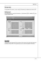
C-3 MS-7612 System Info In the System Info screen, you purchased. Motherboard Click Motherboard to the appearance of your system for reference only and may vary from the product you can read the information of motherboard/ memory/ PCI. Important The pictures in this appendix are for detailed information. Please refer to read the information of motherboard, BIOS, installed CPU and installed graphics card.
C-3 MS-7612 System Info In the System Info screen, you purchased. Motherboard Click Motherboard to the appearance of your system for reference only and may vary from the product you can read the information of motherboard/ memory/ PCI. Important The pictures in this appendix are for detailed information. Please refer to read the information of motherboard, BIOS, installed CPU and installed graphics card.

