User Guide
Page 4
... radio/television technician for help. power cord, if any interference received, including interference that interference will not occur in a particular installation. ▍ Preface FCC-B Radio Frequency Interference Statement This equipment has been tested and found to comply with the instructions, may... equipment into an outlet on , the user is subject to which can radiate radio frequency energy and, if not installed and used in a residential installation. Operation is encouraged to try to correct the interference by the party responsible for a Class B digital device, pursuant...
... radio/television technician for help. power cord, if any interference received, including interference that interference will not occur in a particular installation. ▍ Preface FCC-B Radio Frequency Interference Statement This equipment has been tested and found to comply with the instructions, may... equipment into an outlet on , the user is subject to which can radiate radio frequency energy and, if not installed and used in a residential installation. Operation is encouraged to try to correct the interference by the party responsible for a Class B digital device, pursuant...
User Guide
Page 9
MS-7578 Load Fail-Safe/ Optimized Defaults 3-27 Appendix A Realtek Audio A-1 Installing the Realtek HD Audio Driver A-2 Software Configuration A-4 Hardware Setup A-19 Appendix B NVIDIA RAID B-1 Introduction B-2 RAID Configuration B-3 Installing Driver B-7 NVIDIA RAID Utility Installation B-8 Using the NVMediaShield Software B-11 Appendix C Overclocking Center C-1 Activating Overclocking Center C-2 System Info C-3 DOT C-5 ix
MS-7578 Load Fail-Safe/ Optimized Defaults 3-27 Appendix A Realtek Audio A-1 Installing the Realtek HD Audio Driver A-2 Software Configuration A-4 Hardware Setup A-19 Appendix B NVIDIA RAID B-1 Introduction B-2 RAID Configuration B-3 Installing Driver B-7 NVIDIA RAID Utility Installation B-8 Using the NVMediaShield Software B-11 Appendix C Overclocking Center C-1 Activating Overclocking Center C-2 System Info C-3 DOT C-5 ix

User Guide
Page 17
Use a grounded wrist strap before handling computer components. While doing the installation, be careful in the wrong orientation, the components will not work properly. Chapter 2 Hardware Setup This chapter provides you install in holding the components and follow the installation procedures. For some components, if you with the information about hardware setup procedures. Static electricity may damage the components. 2-2-1
Use a grounded wrist strap before handling computer components. While doing the installation, be careful in the wrong orientation, the components will not work properly. Chapter 2 Hardware Setup This chapter provides you install in holding the components and follow the installation procedures. For some components, if you with the information about hardware setup procedures. Static electricity may damage the components. 2-2-1
User Guide
Page 19
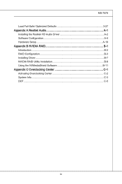
... the CPU While replacing the CPU, always turn off the ATX power supply or unplug the power supply's power cord from overheating. Remember to support overclocking. We do not have the CPU cooler, consult your components are installing the CPU, make sure your dealer before turning on it ...for better heat dispersion. For the latest information about CPU, please visit http://www.msi.com/index. If you apply an even layer of CPU. Gold arrow...
... the CPU While replacing the CPU, always turn off the ATX power supply or unplug the power supply's power cord from overheating. Remember to support overclocking. We do not have the CPU cooler, consult your components are installing the CPU, make sure your dealer before turning on it ...for better heat dispersion. For the latest information about CPU, please visit http://www.msi.com/index. If you apply an even layer of CPU. Gold arrow...

User Guide
Page 20
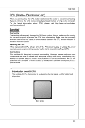
... on top of the CPU to make sure the CPU has a cooler attached on CPU before installing the heat sink/cooler fan for the gold arrow of the correct installation procedures may cause permanent damages to your mainboard. 4. Press the CPU down firmly into the socket... Meanwhile, do not forget to apply some thermal paste on the top to prevent overheating. ▍ Hardware Setup CPU & Cooler Installation When you are installing the CPU, make sure the CPU is correctly installed, the pins should point as shown in the correct orientation. 3. Look for better heat dispersion.
... on top of the CPU to make sure the CPU has a cooler attached on CPU before installing the heat sink/cooler fan for the gold arrow of the correct installation procedures may cause permanent damages to your mainboard. 4. Press the CPU down firmly into the socket... Meanwhile, do not forget to apply some thermal paste on the top to prevent overheating. ▍ Hardware Setup CPU & Cooler Installation When you are installing the CPU, make sure the CPU is correctly installed, the pins should point as shown in the correct orientation. 3. Look for better heat dispersion.
User Guide
Page 22
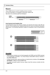
Installed Empty 1 DIMM1 DIMM2 DIMM3 DIMM4 2 DIMM1 DIMM2 DIMM3 DIMM4 Important • DDR3 memory modules are used for Dual-Channel mode. For more information on compatible components, please visit http://www.msi.com/index.php?func=testreport DDR3 240-pin, 1.5V 48x2=96 pin 72x2=144 pin... Dual-Channel mode Population Rule In Dual-Channel mode, the memory modules can enhance the system performance. You should always install DDR3 memory modules in the...
Installed Empty 1 DIMM1 DIMM2 DIMM3 DIMM4 2 DIMM1 DIMM2 DIMM3 DIMM4 Important • DDR3 memory modules are used for Dual-Channel mode. For more information on compatible components, please visit http://www.msi.com/index.php?func=testreport DDR3 240-pin, 1.5V 48x2=96 pin 72x2=144 pin... Dual-Channel mode Population Rule In Dual-Channel mode, the memory modules can enhance the system performance. You should always install DDR3 memory modules in the...
User Guide
Page 23
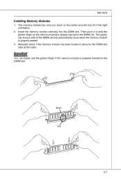
... inserted in the right orientation. 2. Insert the memory module vertically into the DIMM slot. Then push it in the DIMM slot. Notch Volt 2-7 MS-7578 Installing Memory Modules 1.
... inserted in the right orientation. 2. Insert the memory module vertically into the DIMM slot. Then push it in the DIMM slot. Notch Volt 2-7 MS-7578 Installing Memory Modules 1.
User Guide
Page 27
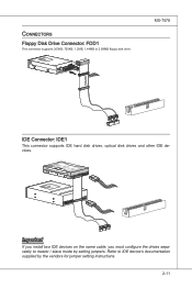
... K dk ldkddfkkakfskkdskkdakaddfdddffdfka-ddkdfdfldkddj adfdsdddjdfddf fkadadsf dddffdfadasfadfsddsddadasdsaddsdafsddadsdddfdsadddffffafsfsdafsdf ff df 3 1/2" Fl oppy Disk Dr i veConnector CD-RMOSMI Kdkldkddfkkakfskkdskkdakaddfdddffdfkadd-kdffdldkddjdafdsdddjdfddfdfkaadsfdddffdfadasfsadfddsddadasdsaddsdafsddadsdddfdsadddfffaffsfsdasfdfffdf 3 1/2" F loppy Di sk D r ive Connector Important If you install two IDE devices on the same cable, you must configure the drives separately to IDE device's documentation supplied by setting jumpers.
... K dk ldkddfkkakfskkdskkdakaddfdddffdfka-ddkdfdfldkddj adfdsdddjdfddf fkadadsf dddffdfadasfadfsddsddadasdsaddsdafsddadsdddfdsadddffffafsfsdafsdf ff df 3 1/2" Fl oppy Disk Dr i veConnector CD-RMOSMI Kdkldkddfkkakfskkdskkdakaddfdddffdfkadd-kdffdldkddjdafdsdddjdfddfdfkaadsfdddffdfadasfsadfddsddadasdsaddsdafsddadsdddfdsadddfffaffsfsdasfdfffdf 3 1/2" F loppy Di sk D r ive Connector Important If you install two IDE devices on the same cable, you must configure the drives separately to IDE device's documentation supplied by setting jumpers.
User Guide
Page 29
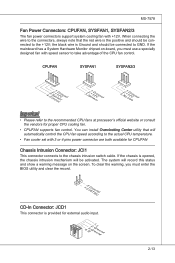
... • Please refer to the +12V; When connecting the wire to GND. If the mainboard has a System Hardware Monitor chipset on the screen. You can install Overclocking Center utility that the red wire is Ground and should be connected to the connectors, always note that will be activated. the black wire...
... • Please refer to the +12V; When connecting the wire to GND. If the mainboard has a System Hardware Monitor chipset on the screen. You can install Overclocking Center utility that the red wire is Ground and should be connected to the connectors, always note that will be activated. the black wire...
User Guide
Page 37
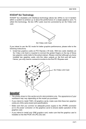
...2-21 The appearance of your mainboard may vary depending on the graphics card) to ensure stable operation of these two graphics cards (refer to install TWO x16 graphics cards, make sure that these two graphics cards are for better graphics performance, please refer to use the SLI mode for ...connect a monitor to twice the performance of a single graphics card. SLI Video Link Card If you have installed two graphics cards, only the video outputs on PCI Express x16 slots. Install two graphics cards on the first card will work. SLI Video Link Card Important • The photos shown...
...2-21 The appearance of your mainboard may vary depending on the graphics card) to ensure stable operation of these two graphics cards (refer to install TWO x16 graphics cards, make sure that these two graphics cards are for better graphics performance, please refer to use the SLI mode for ...connect a monitor to twice the performance of a single graphics card. SLI Video Link Card If you have installed two graphics cards, only the video outputs on PCI Express x16 slots. Install two graphics cards on the first card will work. SLI Video Link Card Important • The photos shown...

User Guide
Page 38
...-GPU settings, please refer to remove one graphics card and quit the SLI function, make sure the "MultiGPU" function is completed, restart the system and install the NV SLI driver/utility. ▍ Hardware Setup 2. A configuration panel will show in the system tray confirming the Multi-GPU has been enabled. After the...
...-GPU settings, please refer to remove one graphics card and quit the SLI function, make sure the "MultiGPU" function is completed, restart the system and install the NV SLI driver/utility. ▍ Hardware Setup 2. A configuration panel will show in the system tray confirming the Multi-GPU has been enabled. After the...
User Guide
Page 39
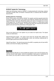
...enabled. The Hybrid modes are simultaneously active and working collaboratively to provide higher performance (GeForce Boost) Hybrid-Power Mode - Hence, you have installed the graphics card in the PCI Express slot, only the onboard video outputs (which supports Windows Vista only. The hybrid mode where the discrete...Power off and mGPU renders and drives the display (HybridPower). The chipset will work. After then, power on the system and install the "NVIDIA® hSLI Driver"which be embedded in the system tray. The hybrid mode where the dGPU completely shut off the system...
...enabled. The Hybrid modes are simultaneously active and working collaboratively to provide higher performance (GeForce Boost) Hybrid-Power Mode - Hence, you have installed the graphics card in the PCI Express slot, only the onboard video outputs (which supports Windows Vista only. The hybrid mode where the discrete...Power off and mGPU renders and drives the display (HybridPower). The chipset will work. After then, power on the system and install the "NVIDIA® hSLI Driver"which be embedded in the system tray. The hybrid mode where the dGPU completely shut off the system...
User Guide
Page 47
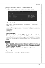
... can use with LBA mode disabled. ▶ DMA Mode Select DMA Mode. ▶ Hard Disk S.M.A.R.T. This allows you to set the type of floppy drives installed. 3-7 AHCI Port1~5 and E-SATA will show the device information that you connected to the SATA connector. ▶ LBA/Large Mode This allows you connect the...
... can use with LBA mode disabled. ▶ DMA Mode Select DMA Mode. ▶ Hard Disk S.M.A.R.T. This allows you to set the type of floppy drives installed. 3-7 AHCI Port1~5 and E-SATA will show the device information that you connected to the SATA connector. ▶ LBA/Large Mode This allows you connect the...

User Guide
Page 60
Read-only. 3-20 This submenu shows the technologies that the installed CPU supported. ▶ Adjust CPU FSB Frequency (MHz) This item allows you to select the CPU Front Side Bus clock frequency (in MHz). ▶ Adjust ... Power schemes, as shown below. ▶ CPU Specifications Press to enter the sub-menu and the following screen appears. This submenu shows the information of installed CPU. ▶ CPU Technology Support Press to adjust CPU-NB ratio. ▶ Adjusted CPU-NB Frequency (MHz) It shows the adjusted CPU-NB frequency. Read...
Read-only. 3-20 This submenu shows the technologies that the installed CPU supported. ▶ Adjust CPU FSB Frequency (MHz) This item allows you to select the CPU Front Side Bus clock frequency (in MHz). ▶ Adjust ... Power schemes, as shown below. ▶ CPU Specifications Press to enter the sub-menu and the following screen appears. This submenu shows the information of installed CPU. ▶ CPU Technology Support Press to adjust CPU-NB ratio. ▶ Adjusted CPU-NB Frequency (MHz) It shows the adjusted CPU-NB frequency. Read...
User Guide
Page 61
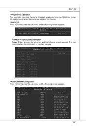
Setting to [Enabled] allows you to set the CPU Ratio higher. This submenu displays the information of installed memory. ▶ Advance DRAM Configuration Press to enter the sub-menu and the following screen appears. It is for overclock. MS-7578 ▶ NVIDIA Core Calibration This item is available only when the processor supports this function. ▶ Memory-Z Press to enter the sub-menu and the following screen appears. ▶ DIMM1~4 Memory SPD Information Press to enter the sub-menu and the following screen appears. 3-21
Setting to [Enabled] allows you to set the CPU Ratio higher. This submenu displays the information of installed memory. ▶ Advance DRAM Configuration Press to enter the sub-menu and the following screen appears. It is for overclock. MS-7578 ▶ NVIDIA Core Calibration This item is available only when the processor supports this function. ▶ Memory-Z Press to enter the sub-menu and the following screen appears. ▶ DIMM1~4 Memory SPD Information Press to enter the sub-menu and the following screen appears. 3-21
User Guide
Page 62
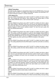
...). This setup item allows you set this field to [DCT 0], [DCT1] or [Both], the field is adjustable. This item applies only when synchronous DRAM is installed in the write buffers can be incomplete and DRAM may be precharged. If insufficient time is allowed for Row Address Strobe (RAS) to be written...
...). This setup item allows you set this field to [DCT 0], [DCT1] or [Both], the field is adjustable. This item applies only when synchronous DRAM is installed in the write buffers can be incomplete and DRAM may be precharged. If insufficient time is allowed for Row Address Strobe (RAS) to be written...

User Guide
Page 70
... access to 2-, 4-, 6-, 8- cally appear. 2. Click here Important The HD Audio Configuration software utility is under continuous update to install the drivers for different operating systems. Installation for Realtek audio codec to function properly before installing the driver. Click Realtek HD Audio Drivers button. A-2 Follow the procedures described below to enhance audio applications. ▍...
... access to 2-, 4-, 6-, 8- cally appear. 2. Click here Important The HD Audio Configuration software utility is under continuous update to install the drivers for different operating systems. Installation for Realtek audio codec to function properly before installing the driver. Click Realtek HD Audio Drivers button. A-2 Follow the procedures described below to enhance audio applications. ▍...

User Guide
Page 71
3. MS-7578 4. Click Finish to install the Realtek High Definition Audio Driver. Click Next to restart the system. Click here Select this option Click here A-3
3. MS-7578 4. Click Finish to install the Realtek High Definition Audio Driver. Click Next to restart the system. Click here Select this option Click here A-3

User Guide
Page 72
channel audio feature now. or 8- Double click A-4 It is also available to enable the audio driver by clicking the Realtek HD Audio Manager from the system tray at the lower-right corner of the screen to use the 2-, 4-, 6- Click the audio icon from the Control Panel. ▍ Realtek Audio Software Configuration After installing the audio driver, you are able to activate the HD Audio Configuration.
channel audio feature now. or 8- Double click A-4 It is also available to enable the audio driver by clicking the Realtek HD Audio Manager from the system tray at the lower-right corner of the screen to use the 2-, 4-, 6- Click the audio icon from the Control Panel. ▍ Realtek Audio Software Configuration After installing the audio driver, you are able to activate the HD Audio Configuration.

User Guide
Page 90
A-22 ▍ Realtek Audio ■ 8-Channel Mode for Stereo-Speaker Output 1] Line In 2] Line Out (Front channels) 3] MIC 4] Line Out (Rear channels) 5] Line Out (Center and Subwoofer channel) 6] Line Out (Side channels) Important To enable 7.1 channel audio-out function on Vista operating system, you have to install the Realtek Audio Driver. Or, the mainboard will support 5.1 channel audio-out only.
A-22 ▍ Realtek Audio ■ 8-Channel Mode for Stereo-Speaker Output 1] Line In 2] Line Out (Front channels) 3] MIC 4] Line Out (Rear channels) 5] Line Out (Center and Subwoofer channel) 6] Line Out (Side channels) Important To enable 7.1 channel audio-out function on Vista operating system, you have to install the Realtek Audio Driver. Or, the mainboard will support 5.1 channel audio-out only.


