User Guide
Page 5
... Installation Procedures 2-2 CPU Core Speed Derivation Procedure 2-4 CPU Clock Selection 2-4 Memory 2-5 Introduction to SDRAM 2-5 DIMM Module Combination 2-6 Installing DIMM Modules 2-6 Power Supply 2-7 ATX 20-Pin Power Connector: JPWR1 2-7 Back Panel 2-8 Mouse Connector 2-8 Keyboard Connector 2-9 USB Connectors 2-9 Serial Port Connector: COM A 2-10 VGA DB 15 Pin Connector 2-10 Parallel Port Connector: LPT1 2-11...
... Installation Procedures 2-2 CPU Core Speed Derivation Procedure 2-4 CPU Clock Selection 2-4 Memory 2-5 Introduction to SDRAM 2-5 DIMM Module Combination 2-6 Installing DIMM Modules 2-6 Power Supply 2-7 ATX 20-Pin Power Connector: JPWR1 2-7 Back Panel 2-8 Mouse Connector 2-8 Keyboard Connector 2-9 USB Connectors 2-9 Serial Port Connector: COM A 2-10 VGA DB 15 Pin Connector 2-10 Parallel Port Connector: LPT1 2-11...
User Guide
Page 6
... Frequency/Voltage Control 3-30 Load Fail-Safe/Optimized Defaults 3-31 vi IrDA Infrared Module Header: JIR1 2-16 CD-In Connector: JCD1 2-16 Front Panel Connectors: JFP1 & JFP2 2-17 Front Panel Audio Connector: JAUD2 2-18 Front USB Connector: JUSB1 2-19 Chassis Intrusion Switch Connector: JCASE1 2-19 Wake On Ring Connector: JMDM1 2-20 Wake...
... Frequency/Voltage Control 3-30 Load Fail-Safe/Optimized Defaults 3-31 vi IrDA Infrared Module Header: JIR1 2-16 CD-In Connector: JCD1 2-16 Front Panel Connectors: JFP1 & JFP2 2-17 Front Panel Audio Connector: JAUD2 2-18 Front USB Connector: JUSB1 2-19 Chassis Intrusion Switch Connector: JCASE1 2-19 Wake On Ring Connector: JMDM1 2-20 Wake...
User Guide
Page 13
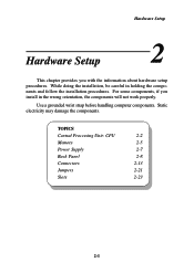
... Hardware Setup This chapter provides you install in holding the components and follow the installation procedures. TOPICS Central Processing Unit: CPU 2-2 Memory 2-5 Power Supply 2-7 Back Panel 2-8 Connectors 2-13 Jumpers 2-21 Slots 2-23 2-1 Hardware Setup 2 Chapter 2. Static electricity may damage the components.
... Hardware Setup This chapter provides you install in holding the components and follow the installation procedures. TOPICS Central Processing Unit: CPU 2-2 Memory 2-5 Power Supply 2-7 Back Panel 2-8 Connectors 2-13 Jumpers 2-21 Slots 2-23 2-1 Hardware Setup 2 Chapter 2. Static electricity may damage the components.
User Guide
Page 20
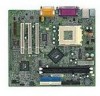
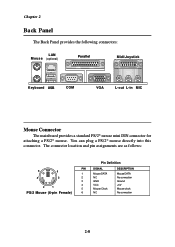
... 6 NC DESCRIPTION Mouse DATA No connection Ground +5V Mouse clock No connection 2-8 You can plug a PS/2® mouse directly into this connector. Chapter 2 Back Panel The Back Panel provides the following connectors: LAN M o u s e (optional) Parallel Midi/Joystick Keyboard USB COM VGA L-out L-in MIC Mouse Connector The mainboard provides a standard PS/2®...
... 6 NC DESCRIPTION Mouse DATA No connection Ground +5V Mouse clock No connection 2-8 You can plug a PS/2® mouse directly into this connector. Chapter 2 Back Panel The Back Panel provides the following connectors: LAN M o u s e (optional) Parallel Midi/Joystick Keyboard USB COM VGA L-out L-in MIC Mouse Connector The mainboard provides a standard PS/2®...

User Guide
Page 28
You must configure the setting through the BIOS setup to IrDA Infrared module. JIR1 is for CD-ROM audio connector. JIR1 6 5 2 1 L GND R JCD1 2-16 JIR1 Pin Definition Pin Signal 1 NC 2 NC 3 VCC 4 GND 5 IRTX 6 IRRX CD-In Connector: JCD1 JCD1 connector is compliant with Intel® Front Panel I/O Connectivity Design Guide. Chapter 2 IrDA Infrared Module Header: JIR1 The connector allows you to connect to use the IR function.
You must configure the setting through the BIOS setup to IrDA Infrared module. JIR1 is for CD-ROM audio connector. JIR1 6 5 2 1 L GND R JCD1 2-16 JIR1 Pin Definition Pin Signal 1 NC 2 NC 3 VCC 4 GND 5 IRTX 6 IRRX CD-In Connector: JCD1 JCD1 connector is compliant with Intel® Front Panel I/O Connectivity Design Guide. Chapter 2 IrDA Infrared Module Header: JIR1 The connector allows you to connect to use the IR function.
User Guide
Page 29
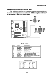
... for electrical connection to GND Reserved. JFP1 is compliant with Intel® Front Panel I/O Connectivity Design Guide. JFP2 Pin Definition PIN SIGNAL 1 GND 3 SLED 5 PLED 7 NC PIN SIGNAL 2 SPK- 4 BUZ+ 6 BUZ- 8 SPK+ 2-17 Do not use. JFP2 8 7 Speaker Power ... pull-down to GND Power Switch high reference pull-up Reset Switch high reference pull-up Power Switch low reference pull-down to the front panel switches and LEDs.
... for electrical connection to GND Reserved. JFP1 is compliant with Intel® Front Panel I/O Connectivity Design Guide. JFP2 Pin Definition PIN SIGNAL 1 GND 3 SLED 5 PLED 7 NC PIN SIGNAL 2 SPK- 4 BUZ+ 6 BUZ- 8 SPK+ 2-17 Do not use. JFP2 8 7 Speaker Power ... pull-down to GND Power Switch high reference pull-up Reset Switch high reference pull-up Power Switch low reference pull-down to the front panel switches and LEDs.
User Guide
Page 30
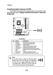
... Microphone power 4 AUD_VCC Filtered +5V used by analog audio circuits 5 AUD_FPOUT_R Right channel audio signal to front panel 6 AUD_RET_R Right channel audio signal return from front panel 7 HP_ON Reserved for future use to control headphone amplifier 8 KEY No pin 9 AUD_FPOUT_L Left channel audio signal... to front panel 10 AUD_RET_L Left channel audio signal return from front panel Note: If you don't want to connect to the front audio header, pins 5 & 6, 9 & 10...
... Microphone power 4 AUD_VCC Filtered +5V used by analog audio circuits 5 AUD_FPOUT_R Right channel audio signal to front panel 6 AUD_RET_R Right channel audio signal return from front panel 7 HP_ON Reserved for future use to control headphone amplifier 8 KEY No pin 9 AUD_FPOUT_L Left channel audio signal... to front panel 10 AUD_RET_L Left channel audio signal return from front panel Note: If you don't want to connect to the front audio header, pins 5 & 6, 9 & 10...

User Guide
Page 31
... 2 USBPWR 3 USBP2- 4 USBP3- 5 USBP2+ 6 USBP3+ 7 GND 8 GND 9 NC 10 USBOC 1 2 JUSB1 9 10 Chassis Intrusion Switch Connector: JCASE1 This connector is compliant with Intel® Front Panel I/O Connectivity Design Guide. If the chassis is opened, the switch will record this status and show a warning message on the screen.
... 2 USBPWR 3 USBP2- 4 USBP3- 5 USBP2+ 6 USBP3+ 7 GND 8 GND 9 NC 10 USBOC 1 2 JUSB1 9 10 Chassis Intrusion Switch Connector: JCASE1 This connector is compliant with Intel® Front Panel I/O Connectivity Design Guide. If the chassis is opened, the switch will record this status and show a warning message on the screen.

