User Guide
Page 6
... Slots 2-23 CNR (Communication Network Riser) Slot 2-23 ISA Slot (Optional 2-23 PCI Interrupt Request Routing 2-24 Chapter 3. BIOS Setup 3-1 Entering Setup 3-2 Control Keys 3-2 Getting Help 3-3 The Main Menu 3-4 Standard CMOS Features 3-6 Advanced BIOS Features 3-8 Advanced Chipset Features 3-12 Integrated Peripherals 3-16 Power Management Setup 3-21 PnP/PCI Configurations 3-26 PC Health...
... Slots 2-23 CNR (Communication Network Riser) Slot 2-23 ISA Slot (Optional 2-23 PCI Interrupt Request Routing 2-24 Chapter 3. BIOS Setup 3-1 Entering Setup 3-2 Control Keys 3-2 Getting Help 3-3 The Main Menu 3-4 Standard CMOS Features 3-6 Advanced BIOS Features 3-8 Advanced Chipset Features 3-12 Integrated Peripherals 3-16 Power Management Setup 3-21 PnP/PCI Configurations 3-26 PC Health...
User Guide
Page 10
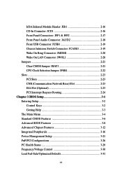
.../HPSIR - 1 VGA port - 1 Audio/Game port Network (Optional) ADMtek AN983B Audio Audio controller integrated in 686B chipset Software audio codec Realtek ALC101T - Dimension Micro-ATX Form Factor: 24.4 cm (L) x 21.5 cm (W) Mounting 6 mounting holes Others Suspend to Disk S4/S3 Plug and Play function Supports PCI 2.2 Hardware Monitoring...Desktop Management Interface (DMI) function which detects the peripheral devices and expansion cards of the board automatically. Onboard Front Audio Pin Header BIOS The mainboard BIOS provides "Plug & Play" BIOS which records your mainboard specifications.
.../HPSIR - 1 VGA port - 1 Audio/Game port Network (Optional) ADMtek AN983B Audio Audio controller integrated in 686B chipset Software audio codec Realtek ALC101T - Dimension Micro-ATX Form Factor: 24.4 cm (L) x 21.5 cm (W) Mounting 6 mounting holes Others Suspend to Disk S4/S3 Plug and Play function Supports PCI 2.2 Hardware Monitoring...Desktop Management Interface (DMI) function which detects the peripheral devices and expansion cards of the board automatically. Onboard Front Audio Pin Header BIOS The mainboard BIOS provides "Plug & Play" BIOS which records your mainboard specifications.
User Guide
Page 26
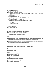
...-ROM, 120MB Floppy (reserved for jumper setting instructions. 2-14 You can connect up to the hard disk documentation supplied by hard disk vendors for future BIOS) and other devices. IDE1 can also connect a Master and a Slave drive. You must configure the second drive to Slave mode by setting the jumper accordingly...
...-ROM, 120MB Floppy (reserved for jumper setting instructions. 2-14 You can connect up to the hard disk documentation supplied by hard disk vendors for future BIOS) and other devices. IDE1 can also connect a Master and a Slave drive. You must configure the second drive to Slave mode by setting the jumper accordingly...

User Guide
Page 28
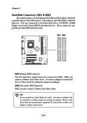
Chapter 2 IrDA Infrared Module Header: JIR1 The connector allows you to connect to use the IR function. JIR1 6 5 2 1 L GND R JCD1 2-16 JIR1 is for CD-ROM audio connector. JIR1 Pin Definition Pin Signal 1 NC 2 NC 3 VCC 4 GND 5 IRTX 6 IRRX CD-In Connector: JCD1 JCD1 connector is compliant with Intel® Front Panel I/O Connectivity Design Guide. You must configure the setting through the BIOS setup to IrDA Infrared module.
Chapter 2 IrDA Infrared Module Header: JIR1 The connector allows you to connect to use the IR function. JIR1 6 5 2 1 L GND R JCD1 2-16 JIR1 is for CD-ROM audio connector. JIR1 Pin Definition Pin Signal 1 NC 2 NC 3 VCC 4 GND 5 IRTX 6 IRRX CD-In Connector: JCD1 JCD1 connector is compliant with Intel® Front Panel I/O Connectivity Design Guide. You must configure the setting through the BIOS setup to IrDA Infrared module.

User Guide
Page 31
... This connector is opened, the switch will record this status and show a warning message on the screen. To clear the warning, you must enter the BIOS utility and clear the record. 2-19 JCASE1 Hardware Setup Front USB Connector: JUSB1 The mainboard provides one front Universal Serial Bus connector for users to...
... This connector is opened, the switch will record this status and show a warning message on the screen. To clear the warning, you must enter the BIOS utility and clear the record. 2-19 JCASE1 Hardware Setup Front USB Connector: JUSB1 The mainboard provides one front Universal Serial Bus connector for users to...
User Guide
Page 35
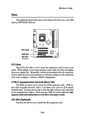
... (OPTIONAL) PCI Slots Three PCI slots allow you unplug the power supply first. CNR is done through software and controlled by the motherboard's chipset. Meanwhile, read the documentation for the expansion card to meet your needs. Its main processing is a specially designed network, audio..., or modem riser card for the expansion card, such as jumpers, switches or BIOS configuration. When adding or removing expansion cards, make any necessary hardware or software settings for ATX family motherboards. Please note the CNR slot of the mainboard only supports audio and modem that you...
... (OPTIONAL) PCI Slots Three PCI slots allow you unplug the power supply first. CNR is done through software and controlled by the motherboard's chipset. Meanwhile, read the documentation for the expansion card to meet your needs. Its main processing is a specially designed network, audio..., or modem riser card for the expansion card, such as jumpers, switches or BIOS configuration. When adding or removing expansion cards, make any necessary hardware or software settings for ATX family motherboards. Please note the CNR slot of the mainboard only supports audio and modem that you...
User Guide
Page 37
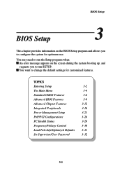
... Configurations 3-26 PC Health Status 3-29 Frequency/Voltage Control 3-30 Load Fail-Safe/Optimized Defaults 3-31 Set Supervisor/User Password 3-32 3-1 BIOS Setup BIOS Setup This chapter provides information on the BIOS Setup program and allows you to run the Setup program when: An error message appears on the screen during the system...
... Configurations 3-26 PC Health Status 3-29 Frequency/Voltage Control 3-30 Load Fail-Safe/Optimized Defaults 3-31 Set Supervisor/User Password 3-32 3-1 BIOS Setup BIOS Setup This chapter provides information on the BIOS Setup program and allows you to run the Setup program when: An error message appears on the screen during the system...
User Guide
Page 39
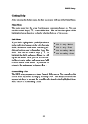
BIOS Setup Getting Help After entering the Setup menu, the first menu you want to return to select the item. Then you can make changes to ...- Sub-Menu If you can use control keys ( ↑↓ ) to 8 highlight the field and press to call up the sub-menu. General Help The BIOS setup program provides a General Help screen. You can call up this 8 field. Main Menu The main menu lists the setup functions you find a right pointer...
BIOS Setup Getting Help After entering the Setup menu, the first menu you want to return to select the item. Then you can make changes to ...- Sub-Menu If you can use control keys ( ↑↓ ) to 8 highlight the field and press to call up the sub-menu. General Help The BIOS setup program provides a General Help screen. You can call up this 8 field. Main Menu The main menu lists the setup functions you find a right pointer...
User Guide
Page 40
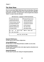
... Standard CMOS Features Use this menu to set the Advanced Features available on the screen. Advanced BIOS Features Use this menu for integrated peripherals. 3-4 Integrated Peripherals Use this menu to change the values in BIOS F10 : Save & Exit Setup Select Item Time, Date, Hard Disk Type... Advanced Chipset ...Chapter 3 The Main Menu Once you to select from twelve setup functions and two exit choices. The Main Menu allows you enter Award® BIOS CMOS Setup Utility, the Main Menu will appear on your system. CMOS Setup Utility - Use arrow keys to select among the items and ...
... Standard CMOS Features Use this menu to set the Advanced Features available on the screen. Advanced BIOS Features Use this menu for integrated peripherals. 3-4 Integrated Peripherals Use this menu to change the values in BIOS F10 : Save & Exit Setup Select Item Time, Date, Hard Disk Type... Advanced Chipset ...Chapter 3 The Main Menu Once you to select from twelve setup functions and two exit choices. The Main Menu allows you enter Award® BIOS CMOS Setup Utility, the Main Menu will appear on your system. CMOS Setup Utility - Use arrow keys to select among the items and ...
User Guide
Page 41
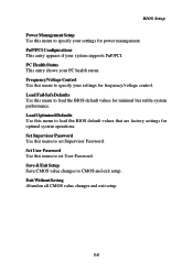
... values that are factory settings for minimal but stable system performance. Set User Password Use this menu to load the BIOS default values for optimal system operations. Exit Without Saving Abandon all CMOS value changes and exit setup. 3-5 PnP/PCI Configurations This entry...Load Fail-Safe Defaults Use this menu to set Supervisor Password. Set Supervisor Password Use this menu to specify your settings for power management. BIOS Setup Power Management Setup Use this menu to set User Password. Frequency/Voltage Control Use this menu to specify your settings for frequency/voltage ...
... values that are factory settings for minimal but stable system performance. Set User Password Use this menu to load the BIOS default values for optimal system operations. Exit Without Saving Abandon all CMOS value changes and exit setup. 3-5 PnP/PCI Configurations This entry...Load Fail-Safe Defaults Use this menu to set Supervisor Password. Set Supervisor Password Use this menu to specify your settings for power management. BIOS Setup Power Management Setup Use this menu to set User Password. Frequency/Voltage Control Use this menu to specify your settings for frequency/voltage ...

User Guide
Page 42
Note that 3-6 CMOS Setup Utility - through Dec. IDE Primary/Secondary Master/Slave Press PgUp/ or PgDn/ to 31 can by adjusted by BIOS. Each category includes no, one or more than one setup items. Use the arrow keys to highlight the item and then use the or keys ...
Note that 3-6 CMOS Setup Utility - through Dec. IDE Primary/Secondary Master/Slave Press PgUp/ or PgDn/ to 31 can by adjusted by BIOS. Each category includes no, one or more than one setup items. Use the arrow keys to highlight the item and then use the or keys ...
User Guide
Page 43
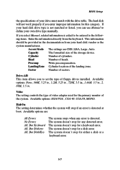
... are : All Errors No Errors All, But Keyboard All, But Diskette All, But Disk/Key The system stops when any detected error. Precomp Write precompensation. BIOS Setup the specifications of the system. Cylinder Number of heads. The system doesn't stop for a keyboard error. The system doesn't stop for any error is...
... are : All Errors No Errors All, But Keyboard All, But Diskette All, But Disk/Key The system stops when any detected error. Precomp Write precompensation. BIOS Setup the specifications of the system. Cylinder Number of heads. The system doesn't stop for a keyboard error. The system doesn't stop for any error is...
User Guide
Page 44
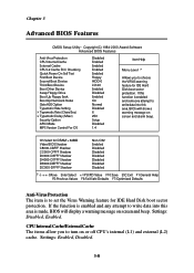
...allow you to set the Virus Warning feature for IDE Hard Disk boot sector protection. OS Select for DRAM > 64MB Video BIOS Shadow C8000-CBFFF Shadow CC000-CFFFF Shadow D0000-D3FFF Shadow D4000-D7FFF Shadow D8000-DBFFF Shadow DC000-DFFFF Shadow Non-OS2 Enabled ... (L1) and external (L2) cache. Settings: Disabled, Enabled. Settings: Enabled, Disabled. 3-8 Chapter 3 Advanced BIOS Features CMOS Setup Utility - Copyright(C) 1984-2000 Award Software Advanced BIOS Features Anti-Virus Protection CPU Internal Cache External Cache CPU L2 Cache ECC Checking Quick Power On Self Test First...
...allow you to set the Virus Warning feature for IDE Hard Disk boot sector protection. OS Select for DRAM > 64MB Video BIOS Shadow C8000-CBFFF Shadow CC000-CFFFF Shadow D0000-D3FFF Shadow D4000-D7FFF Shadow D8000-DBFFF Shadow DC000-DFFFF Shadow Non-OS2 Enabled ... (L1) and external (L2) cache. Settings: Disabled, Enabled. Settings: Enabled, Disabled. 3-8 Chapter 3 Advanced BIOS Features CMOS Setup Utility - Copyright(C) 1984-2000 Award Software Advanced BIOS Features Anti-Virus Protection CPU Internal Cache External Cache CPU L2 Cache ECC Checking Quick Power On Self Test First...
User Guide
Page 45
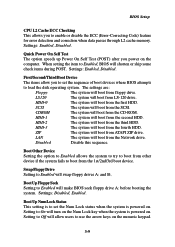
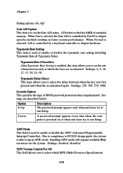
... On Self Test The option speeds up Power On Self Test (POST) after you power on the numeric keypad. 3-9 When setting the item to Enabled, BIOS will swap floppy drives A: and B:. HDD-1 The system will boot from LS-120 drive. Boot Other Device Setting the option to Enabled allows the system... drive. HDD-3 The system will boot from the second HDD. Boot Up NumLock Status This setting is to set the sequence of boot devices where BIOS attempts to boot from the first HDD. Setting to Off will boot from the fourth HDD. Settings: Enabled, Disabled. ZIP The system will boot from...
... On Self Test The option speeds up Power On Self Test (POST) after you power on the numeric keypad. 3-9 When setting the item to Enabled, BIOS will swap floppy drives A: and B:. HDD-1 The system will boot from LS-120 drive. Boot Other Device Setting the option to Enabled allows the system... drive. HDD-3 The system will boot from the second HDD. Boot Up NumLock Status This setting is to set the sequence of boot devices where BIOS attempts to boot from the first HDD. Setting to Off will boot from the fourth HDD. Settings: Enabled, Disabled. ZIP The system will boot from...
User Guide
Page 46
... prompt appears every time when the computer is to run Setup. MPS Version Control For OS This field allows you to the first 64KB of BIOS password protection that is controlled by Port92 or chipset specific method resulting in APIC mode. Typematic Delay (Msec) This item allows you to select which...
... prompt appears every time when the computer is to run Setup. MPS Version Control For OS This field allows you to the first 64KB of BIOS password protection that is controlled by Port92 or chipset specific method resulting in APIC mode. Typematic Delay (Msec) This item allows you to select which...
User Guide
Page 47
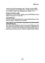
...whether the contents of the adapter ROM named in the items will be copied into the correct area of RAM. Video BIOS Shadow This item sets if the Video BIOS will be copied to improve the performance of ROM firmware for the operating system. You need to know the address of... Non-OS2, OS2. You need to run the OS/2® operating system with DRAM greater than 64MB. Settings: Enabled, Disabled. Settings: Enabled, Disabled. 3-11 BIOS Setup version to use, consult the vendor of your operating system. Settings: 1.4, 1.1. To find out which version to be used for adapters.
...whether the contents of the adapter ROM named in the items will be copied into the correct area of RAM. Video BIOS Shadow This item sets if the Video BIOS will be copied to improve the performance of ROM firmware for the operating system. You need to know the address of... Non-OS2, OS2. You need to run the OS/2® operating system with DRAM greater than 64MB. Settings: Enabled, Disabled. Settings: Enabled, Disabled. 3-11 BIOS Setup version to use, consult the vendor of your operating system. Settings: 1.4, 1.1. To find out which version to be used for adapters.
User Guide
Page 48
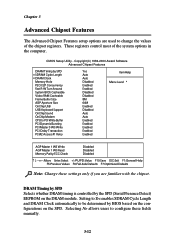
DRAM Timing by SPD Selects whether DRAM timing is controlled by BIOS based on the configurations on the DRAM module. CMOS Setup Utility - Selecting No allows users to configure these settings only if you are used to ...(C) 1984-2000 Award Software Advanced Chipset Features DRAM Timing by SPD x SDRAM Cycle Length x DRAM Clock Memory Hole P2C/C2P Concurrency Fast R-W Turn Around System BIOS Cacheable Video RAM Cacheable Frame Buffer Size AGP Aperture Size OnChip USB USB Keyboard Support OnChip Sound OnChip Modem CPU to be determined by the...
DRAM Timing by SPD Selects whether DRAM timing is controlled by BIOS based on the configurations on the DRAM module. CMOS Setup Utility - Selecting No allows users to configure these settings only if you are used to ...(C) 1984-2000 Award Software Advanced Chipset Features DRAM Timing by SPD x SDRAM Cycle Length x DRAM Clock Memory Hole P2C/C2P Concurrency Fast R-W Turn Around System BIOS Cacheable Video RAM Cacheable Frame Buffer Size AGP Aperture Size OnChip USB USB Keyboard Support OnChip Sound OnChip Modem CPU to be determined by the...
User Guide
Page 49
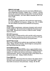
... controls the timing delay (in memory can be reserved for Frame Buffer. Auto allows BIOS to this area is always copied to determine the best DRAM clock frequency. Auto allows BIOS to RAM for faster execution. Settings: Enabled, Disabled. Settings: Enabled, Disabled. Larger... turn around feature for video display (frame). DRAM Clock The chipset supports synchronous and asynchronous mode between host clock and DRAM clock frequency. System BIOS Cacheable System BIOS ROM at F0000h-FFFFFh is reserved, it . Settings: 2M, 4M, 8M. 3-13 Settings: Auto, 2, 3 (clocks). 2 (clocks) ...
... controls the timing delay (in memory can be reserved for Frame Buffer. Auto allows BIOS to this area is always copied to determine the best DRAM clock frequency. Auto allows BIOS to RAM for faster execution. Settings: Enabled, Disabled. Settings: Enabled, Disabled. Larger... turn around feature for video display (frame). DRAM Clock The chipset supports synchronous and asynchronous mode between host clock and DRAM clock frequency. System BIOS Cacheable System BIOS ROM at F0000h-FFFFFh is reserved, it . Settings: 2M, 4M, 8M. 3-13 Settings: Auto, 2, 3 (clocks). 2 (clocks) ...
User Guide
Page 51
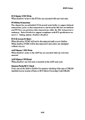
... state is Parity or ECC (Error-Correcting Code) DRAM. 3-15 Memory Parity/ECC Check Users can perform other transactions while the ISA transaction is underway. BIOS Setup PCI Master 0 WS Write When Enabled, writes to the PCI bus are executed with PCI specification version 2.1. PCI Delay Transaction The chipset has an...
... state is Parity or ECC (Error-Correcting Code) DRAM. 3-15 Memory Parity/ECC Check Users can perform other transactions while the ISA transaction is underway. BIOS Setup PCI Master 0 WS Write When Enabled, writes to the PCI bus are executed with PCI specification version 2.1. PCI Delay Transaction The chipset has an...
User Guide
Page 53
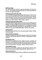
... system automatically determines the best mode for each of block read /write. Init Display First This item specifies which VGA card is used to enable BIOS support. Onboard Lan Device (Optional) The field is available only when LAN is activated. If your IDE hard drive supports it . Onboard FDD Controller ...and want to Disabled if your primary graphics adapter. Onboard Serial Port 1/2 The items specify the base I/O port address and IRQ for faster drive accesses. BIOS Setup IDE Prefetch Mode The onboard IDE drive interfaces supports prefetching, for the onboard Serial Port 3-17
... system automatically determines the best mode for each of block read /write. Init Display First This item specifies which VGA card is used to enable BIOS support. Onboard Lan Device (Optional) The field is available only when LAN is activated. If your IDE hard drive supports it . Onboard FDD Controller ...and want to Disabled if your primary graphics adapter. Onboard Serial Port 1/2 The items specify the base I/O port address and IRQ for faster drive accesses. BIOS Setup IDE Prefetch Mode The onboard IDE drive interfaces supports prefetching, for the onboard Serial Port 3-17


