User Guide
Page 5
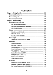
Getting Started 1-1 Mainboard Specification 1-2 Mainboard Layout 1-4 Quick Components Guide 1-5 Chapter 2. CONTENTS Chapter 1. Hardware Setup 2-1 Central Processing Unit: CPU 2-2 CPU Installation Procedures 2-2 CPU Core Speed Derivation Procedure 2-4 CPU Clock Selection 2-4 Memory 2-5 Introduction to SDRAM 2-5 DIMM Module Combination 2-6 Installing DIMM Modules 2-6 Power Supply 2-7 ATX 20-Pin Power Connector: JPWR1 2-7 Back Panel 2-8 Mouse Connector 2-8 Keyboard Connector 2-9 USB...
Getting Started 1-1 Mainboard Specification 1-2 Mainboard Layout 1-4 Quick Components Guide 1-5 Chapter 2. CONTENTS Chapter 1. Hardware Setup 2-1 Central Processing Unit: CPU 2-2 CPU Installation Procedures 2-2 CPU Core Speed Derivation Procedure 2-4 CPU Clock Selection 2-4 Memory 2-5 Introduction to SDRAM 2-5 DIMM Module Combination 2-6 Installing DIMM Modules 2-6 Power Supply 2-7 ATX 20-Pin Power Connector: JPWR1 2-7 Back Panel 2-8 Mouse Connector 2-8 Keyboard Connector 2-9 USB...
User Guide
Page 8
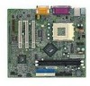
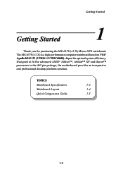
TOPICS Mainboard Specification 1-2 Mainboard Layout 1-4 Quick Components Guide 1-5 1-1 Getting Started 1 Chapter 1. Designed to fit the advanced AMD® Athlon™, Athlon™ XP and Duron™ processors in the 462 pin package, the motherboard provides an inexpensive and professional desktop platform solution. Getting Started Getting Started Thank you for optimal system efficiency. The MS-6378 (v3.X) is a high-performance computer mainboard based on VIA® Apollo KLE133 (VT8361+VT82C686B) chipset for purchasing the MS-6378 (v3.X) Micro-ATX mainboard.
TOPICS Mainboard Specification 1-2 Mainboard Layout 1-4 Quick Components Guide 1-5 1-1 Getting Started 1 Chapter 1. Designed to fit the advanced AMD® Athlon™, Athlon™ XP and Duron™ processors in the 462 pin package, the motherboard provides an inexpensive and professional desktop platform solution. Getting Started Getting Started Thank you for optimal system efficiency. The MS-6378 (v3.X) is a high-performance computer mainboard based on VIA® Apollo KLE133 (VT8361+VT82C686B) chipset for purchasing the MS-6378 (v3.X) Micro-ATX mainboard.
User Guide
Page 9
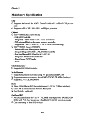
... chipset provides IDE HDD/CDROM with PIO, Bus Master and Ultra DMA 33/66/100 operation modes Can connect up to four IDE devices 1-2 Chapter 1 Mainboard Specification CPU Supports Socket 462 for AMD® Duron™/Athlon™ /Athlon™ XP processors Supports Athlon XP 1900+ MHz and higher processor Chipset...
... chipset provides IDE HDD/CDROM with PIO, Bus Master and Ultra DMA 33/66/100 operation modes Can connect up to four IDE devices 1-2 Chapter 1 Mainboard Specification CPU Supports Socket 462 for AMD® Duron™/Athlon™ /Athlon™ XP processors Supports Athlon XP 1900+ MHz and higher processor Chipset...
User Guide
Page 10
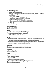
The mainboard provides a Desktop Management Interface (DMI) function which detects the peripheral devices and expansion cards of the board automatically. Dimension Micro-ATX Form Factor: 24.4 cm (L) x 21.5 cm (W) Mounting 6 mounting holes Others Suspend to Disk S4/S3 Plug and Play ...function Supports PCI 2.2 Hardware Monitoring (optional) Modem (External/Internal) Ring Wake up Function LAN Wake up Function 1-3 Onboard Front Audio Pin Header BIOS The mainboard ...
The mainboard provides a Desktop Management Interface (DMI) function which detects the peripheral devices and expansion cards of the board automatically. Dimension Micro-ATX Form Factor: 24.4 cm (L) x 21.5 cm (W) Mounting 6 mounting holes Others Suspend to Disk S4/S3 Plug and Play ...function Supports PCI 2.2 Hardware Monitoring (optional) Modem (External/Internal) Ring Wake up Function LAN Wake up Function 1-3 Onboard Front Audio Pin Header BIOS The mainboard ...
User Guide
Page 14
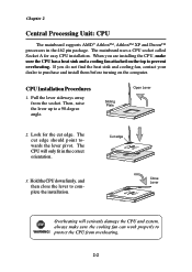
... CPU and system, always make sure the CPU has a heat sink and a cooling fan attached on the computer. plete the installation. The mainboard uses a CPU socket called Socket A for the cut edge should point towards the lever pivot. protect the CPU from the socket. When you... the CPU, make sure the cooling fan can work properly to WARNING! Sliding Plate Open Lever 2. Chapter 2 Central Processing Unit: CPU The mainboard supports AMD® Athlon™, Athlon™ XP and Duron™ processors in the correct orientation. Hold the CPU down firmly, and Close...
... CPU and system, always make sure the CPU has a heat sink and a cooling fan attached on the computer. plete the installation. The mainboard uses a CPU socket called Socket A for the cut edge should point towards the lever pivot. protect the CPU from the socket. When you... the CPU, make sure the cooling fan can work properly to WARNING! Sliding Plate Open Lever 2. Chapter 2 Central Processing Unit: CPU The mainboard supports AMD® Athlon™, Athlon™ XP and Duron™ processors in the correct orientation. Hold the CPU down firmly, and Close...
User Guide
Page 17
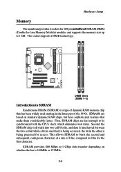
... whether the bus is being accessed, the bit in the other is 100MHz or 133MHz. 2-5 DIMM Slots (DIMM 1~2) Introduction to 1 GB. Hardware Setup Memory The mainboard provides 2 sockets for 168-pin unbuffered SDRAM DIMM (Double In-Line Memory Module) modules and supports the memory size up to SDRAM Synchronous DRAM (SDRAM...
... whether the bus is being accessed, the bit in the other is 100MHz or 133MHz. 2-5 DIMM Slots (DIMM 1~2) Introduction to 1 GB. Hardware Setup Memory The mainboard provides 2 sockets for 168-pin unbuffered SDRAM DIMM (Double In-Line Memory Module) modules and supports the memory size up to SDRAM Synchronous DRAM (SDRAM...
User Guide
Page 19
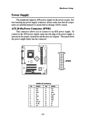
Hardware Setup Power Supply The mainboard supports ATX power supply for the power system. To connect to an ATX power supply. ATX 20-Pin Power Connector: JPWR1 This connector allows you to connect to the ATX power supply, make sure that all components are aligned. Then push down the power supply firmly into the connector. 10...
Hardware Setup Power Supply The mainboard supports ATX power supply for the power system. To connect to an ATX power supply. ATX 20-Pin Power Connector: JPWR1 This connector allows you to connect to the ATX power supply, make sure that all components are aligned. Then push down the power supply firmly into the connector. 10...
User Guide
Page 20
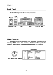
.... Chapter 2 Back Panel The Back Panel provides the following connectors: LAN M o u s e (optional) Parallel Midi/Joystick Keyboard USB COM VGA L-out L-in MIC Mouse Connector The mainboard provides a standard PS/2® mouse mini DIN connector for attaching a PS/2® mouse.
.... Chapter 2 Back Panel The Back Panel provides the following connectors: LAN M o u s e (optional) Parallel Midi/Joystick Keyboard USB COM VGA L-out L-in MIC Mouse Connector The mainboard provides a standard PS/2® mouse mini DIN connector for attaching a PS/2® mouse.
User Guide
Page 21
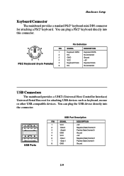
...pin Female) 5 6 Keyboard DATA NC GND VCC Keyboard Clock NC Keyboard DATA No connection Ground +5V Keyboard clock No connection USB Connectors The mainboard provides a UHCI (Universal Host Controller Interface) Universal Serial Bus root for attaching a PS/2® keyboard. You can plug a PS/2® ...Positive Data Channel 0 Ground +5V Negative Data Channel 1 Positive Data Channel 1 Ground 2-9 Hardware Setup Keyboard Connector The mainboard provides a standard PS/2® keyboard mini DIN connector for attaching USB devices such as keyboard, mouse or other USB-compatible devices.
...pin Female) 5 6 Keyboard DATA NC GND VCC Keyboard Clock NC Keyboard DATA No connection Ground +5V Keyboard clock No connection USB Connectors The mainboard provides a UHCI (Universal Host Controller Interface) Universal Serial Bus root for attaching a PS/2® keyboard. You can plug a PS/2® ...Positive Data Channel 0 Ground +5V Negative Data Channel 1 Positive Data Channel 1 Ground 2-9 Hardware Setup Keyboard Connector The mainboard provides a standard PS/2® keyboard mini DIN connector for attaching USB devices such as keyboard, mouse or other USB-compatible devices.
User Guide
Page 22
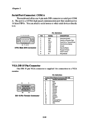
... Connector One DB 15-pin VGA connector is a 16550A high speed communication port that sends/receives 16 bytes FIFOs. Chapter 2 Serial Port Connector: COM A The mainboard offers one 9-pin male DIN connector as serial port COM A.
... Connector One DB 15-pin VGA connector is a 16550A high speed communication port that sends/receives 16 bytes FIFOs. Chapter 2 Serial Port Connector: COM A The mainboard offers one 9-pin male DIN connector as serial port COM A.
User Guide
Page 23
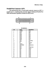
Hardware Setup Parallel Port Connector: LPT1 The mainboard provides a 25-pin female centronic connector as LPT. A parallel port is a standard printer port that supports Enhanced Parallel Port (EPP) and Extended Capabilities Parallel Port (...
Hardware Setup Parallel Port Connector: LPT1 The mainboard provides a 25-pin female centronic connector as LPT. A parallel port is a standard printer port that supports Enhanced Parallel Port (EPP) and Extended Capabilities Parallel Port (...

User Guide
Page 24
.... Audio Port Connectors Line Out is used for microphones. 1/8" Stereo Audio Connectors Line Out Line In MIC 2-12 Chapter 2 LAN (RJ-45) Jack (Optional) The mainboard provides one standard RJ-45 jack for Speakers or Headphones. Pin Definition PIN SIGNAL 1 TDP 2 TDN 3 RDP 4 NC 5 NC 6 RDN 7 NC 8 NC DESCRIPTION Transmit Differential...
.... Audio Port Connectors Line Out is used for microphones. 1/8" Stereo Audio Connectors Line Out Line In MIC 2-12 Chapter 2 LAN (RJ-45) Jack (Optional) The mainboard provides one standard RJ-45 jack for Speakers or Headphones. Pin Definition PIN SIGNAL 1 TDP 2 TDN 3 RDP 4 NC 5 NC 6 RDN 7 NC 8 NC DESCRIPTION Transmit Differential...
User Guide
Page 25
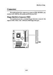
FDD1 2-13 Floppy Disk Drive Connector: FDD1 The mainboard provides a standard floppy disk drive connector that supports 360K, 720K, 1.2M, 1.44M and 2.88M floppy disk types. Hardware Setup Connectors The mainboard provides connectors to connect to FDD, IDE HDD, case, modem, LAN, USB Ports, IR module and CPU/System FAN.
FDD1 2-13 Floppy Disk Drive Connector: FDD1 The mainboard provides a standard floppy disk drive connector that supports 360K, 720K, 1.2M, 1.44M and 2.88M floppy disk types. Hardware Setup Connectors The mainboard provides connectors to connect to FDD, IDE HDD, case, modem, LAN, USB Ports, IR module and CPU/System FAN.
User Guide
Page 26
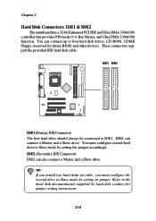
... IDE hard disk cable. You can connect up to the hard disk documentation supplied by setting its jumper. Chapter 2 Hard Disk Connectors: IDE1 & IDE2 The mainboard has a 32-bit Enhanced PCI IDE and Ultra DMA 33/66/100 controller that provides PIO mode 0~4, Bus Master, and Ultra DMA 33/66/100...
... IDE hard disk cable. You can connect up to the hard disk documentation supplied by setting its jumper. Chapter 2 Hard Disk Connectors: IDE1 & IDE2 The mainboard has a 32-bit Enhanced PCI IDE and Ultra DMA 33/66/100 controller that provides PIO mode 0~4, Bus Master, and Ultra DMA 33/66/100...
User Guide
Page 27
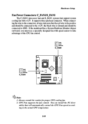
If the mainboard has a System Hardware Monitor chipset on-board, you must use a specially designed fan with +12V. Always consult the vendor for proper CPU cooling fan. 2. Hardware ...
If the mainboard has a System Hardware Monitor chipset on-board, you must use a specially designed fan with +12V. Always consult the vendor for proper CPU cooling fan. 2. Hardware ...
User Guide
Page 29
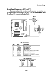
... high reference pull-up Power Switch low reference pull-down to the front panel switches and LEDs. Hardware Setup Front Panel Connectors: JFP1 & JFP2 The mainboard provides two front panel connectors for electrical connection to GND Reserved.
... high reference pull-up Power Switch low reference pull-down to the front panel switches and LEDs. Hardware Setup Front Panel Connectors: JFP1 & JFP2 The mainboard provides two front panel connectors for electrical connection to GND Reserved.

User Guide
Page 31
... clear the record. 2-19 JCASE1 If the chassis is compliant with Intel® Front Panel I/O Connectivity Design Guide. Hardware Setup Front USB Connector: JUSB1 The mainboard provides one front Universal Serial Bus connector for users to connect to a 2-pin chassis switch.
... clear the record. 2-19 JCASE1 If the chassis is compliant with Intel® Front Panel I/O Connectivity Design Guide. Hardware Setup Front USB Connector: JUSB1 The mainboard provides one front Universal Serial Bus connector for users to connect to a 2-pin chassis switch.
User Guide
Page 33
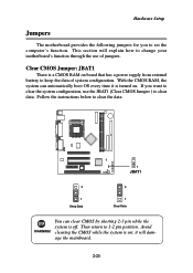
Clear CMOS Jumper: JBAT1 There is turned on board that has a power supply from external battery to change your motherboard's function through the use the JBAT1 (Clear CMOS Jumper ) to clear the data: 1 JBAT1 3 1 Keep Data 3... shorting 2-3 pin while the system is on; Then return to set the computer's function. Hardware Setup Jumpers The motherboard provides the following jumpers for you want to clear the system configuration, use of system configuration. You can automatically boot...system is off. If you to 1-2 pin position. This section will damage the mainboard. 2-21
Clear CMOS Jumper: JBAT1 There is turned on board that has a power supply from external battery to change your motherboard's function through the use the JBAT1 (Clear CMOS Jumper ) to clear the data: 1 JBAT1 3 1 Keep Data 3... shorting 2-3 pin while the system is on; Then return to set the computer's function. Hardware Setup Jumpers The motherboard provides the following jumpers for you want to clear the system configuration, use of system configuration. You can automatically boot...system is off. If you to 1-2 pin position. This section will damage the mainboard. 2-21
User Guide
Page 35
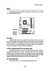
...supply first. CNR is done through software and controlled by the motherboard's chipset. Meanwhile, read the documentation for the expansion card to install the ISA expansion card. 2-23 Please note the CNR slot of the mainboard only supports audio and modem that you to make sure that... are set in Slave (Secondary) mode. When adding or removing expansion cards, make any necessary hardware or software settings for ATX family motherboards. Hardware Setup Slots The motherboard provides three 32-bit ...
...supply first. CNR is done through software and controlled by the motherboard's chipset. Meanwhile, read the documentation for the expansion card to install the ISA expansion card. 2-23 Please note the CNR slot of the mainboard only supports audio and modem that you to make sure that... are set in Slave (Secondary) mode. When adding or removing expansion cards, make any necessary hardware or software settings for ATX family motherboards. Hardware Setup Slots The motherboard provides three 32-bit ...

User Guide
Page 50
... Support Set to Enabled if your system contains a Universal Serial Bus (USB) controller and you have any translation. OnChip Modem Auto allows the mainboard to use a USB keyboard in the operating system that does not support or have USB peripherals. Then burstable transactions burst on the PCI bus ... controller cards to detect whether an audio device is detected, the onboard modem controller will be enabled; OnChip Sound Auto allows the mainboard to connect a modem. If the device is used . PCI Dynamic Bursting When Enabled, every write transaction goes to the write buffer.
... Support Set to Enabled if your system contains a Universal Serial Bus (USB) controller and you have any translation. OnChip Modem Auto allows the mainboard to use a USB keyboard in the operating system that does not support or have USB peripherals. Then burstable transactions burst on the PCI bus ... controller cards to detect whether an audio device is detected, the onboard modem controller will be enabled; OnChip Sound Auto allows the mainboard to connect a modem. If the device is used . PCI Dynamic Bursting When Enabled, every write transaction goes to the write buffer.


