User Manual
Page 1
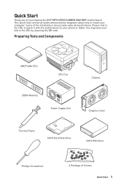
... and Components AMD® AM4 CPU CPU Fan DDR4 Memory Power Supply Unit Chassis Graphics Card Thermal Paste SATA Hard Disk Drive SATA DVD Drive Phillips Screwdriver A Package of the installations also provide video demonstrations. You may have even link to watch it with the web browser on your computer. This Quick Start section provides demonstration diagrams about how to install your phone or tablet. Quick Start Thank you for purchasing the MSI® MPG X570S CARBON MAX WIFI motherboard.
... and Components AMD® AM4 CPU CPU Fan DDR4 Memory Power Supply Unit Chassis Graphics Card Thermal Paste SATA Hard Disk Drive SATA DVD Drive Phillips Screwdriver A Package of the installations also provide video demonstrations. You may have even link to watch it with the web browser on your computer. This Quick Start section provides demonstration diagrams about how to install your phone or tablet. Quick Start Thank you for purchasing the MSI® MPG X570S CARBON MAX WIFI motherboard.
User Manual
Page 15
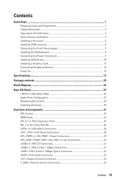
...2 Case stand-off notification 3 Avoid collision notification 3 Installing a Processor 4 Installing DDR4 memory 6 Connecting the Front Panel Header 7 Installing the Motherboard 8 Connecting the Power Connectors 9 Installing SATA Drives 10 Installing a Graphics Card 11 Connecting Peripheral Devices 12 Power On...13 Specifications...17 Package contents 25 Block Diagram ...26 Rear I/O Panel...27 LAN Port LED Status Table 27 Audio Ports Configuration 27 Realtek Audio Console 28 Installing Antennas 30 Overview of Components 31 CPU Socket ...33 DIMM Slots...34 PCI_E1~4: PCIe Expansion...
...2 Case stand-off notification 3 Avoid collision notification 3 Installing a Processor 4 Installing DDR4 memory 6 Connecting the Front Panel Header 7 Installing the Motherboard 8 Connecting the Power Connectors 9 Installing SATA Drives 10 Installing a Graphics Card 11 Connecting Peripheral Devices 12 Power On...13 Specifications...17 Package contents 25 Block Diagram ...26 Rear I/O Panel...27 LAN Port LED Status Table 27 Audio Ports Configuration 27 Realtek Audio Console 28 Installing Antennas 30 Overview of Components 31 CPU Socket ...33 DIMM Slots...34 PCI_E1~4: PCIe Expansion...
User Manual
Page 16
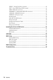
... Tuning Controller connector 44 JBAT1: Clear CMOS (Reset BIOS) Jumper 44 JRGB1: RGB LED connectors 45 JRAINBOW1~2: Addressable RGB LED connectors 46 JCORSAIR1: CORSAIR Connector 47 JPWRLED1: LED power input 48 EZ Debug LED...48 LED_SW1: EZ LED Control 48 Debug Code LED 49 Hexadecimal Character Table 49 Boot Phases...49 Debug Code LED Table 49 Installing OS, Drivers & MSI Center 54 Installing Windows® 10 54 Installing Drivers 54 MSI Center ...54 UEFI BIOS...55 BIOS Setup ...56 Entering BIOS Setup 56 BIOS User Guide 56 Resetting BIOS...57 Updating BIOS...57 RAID Configuration...
... Tuning Controller connector 44 JBAT1: Clear CMOS (Reset BIOS) Jumper 44 JRGB1: RGB LED connectors 45 JRAINBOW1~2: Addressable RGB LED connectors 46 JCORSAIR1: CORSAIR Connector 47 JPWRLED1: LED power input 48 EZ Debug LED...48 LED_SW1: EZ LED Control 48 Debug Code LED 49 Hexadecimal Character Table 49 Boot Phases...49 Debug Code LED Table 49 Installing OS, Drivers & MSI Center 54 Installing Windows® 10 54 Installing Drivers 54 MSI Center ...54 UEFI BIOS...55 BIOS Setup ...56 Entering BIOS Setup 56 BIOS User Guide 56 Resetting BIOS...57 Updating BIOS...57 RAID Configuration...
User Manual
Page 19
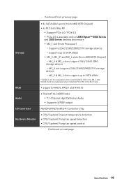
... be unavailable when installing PCIe SSD in the M2_3 slot; Continued from previous page Storage RAID Audio I/O Controller Hardware Monitor ∙∙8x SATA 6Gb/s ports (from AMD X570 Chipset) ∙∙4x M.2 slots (Key M) ▪▪Support PCIe 4.0 / PCIe 3.0 ▪▪PCIe 4.0 is available only on AMD Ryzen™ 5000 Series and 3000 Series desktop processors ▪▪M2_1 slot (from Processor) ▫▫Supports 2242/ 2260/2280/22110 storage devices ▫▫Supports up to SATA 6Gb/s ▪▪...
... be unavailable when installing PCIe SSD in the M2_3 slot; Continued from previous page Storage RAID Audio I/O Controller Hardware Monitor ∙∙8x SATA 6Gb/s ports (from AMD X570 Chipset) ∙∙4x M.2 slots (Key M) ▪▪Support PCIe 4.0 / PCIe 3.0 ▪▪PCIe 4.0 is available only on AMD Ryzen™ 5000 Series and 3000 Series desktop processors ▪▪M2_1 slot (from Processor) ▫▫Supports 2242/ 2260/2280/22110 storage devices ▫▫Supports up to SATA 6Gb/s ▪▪...
User Manual
Page 20
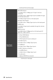
...;4x USB 2.0 Type-A ports available through the internal connectors AMD Processor ∙∙4x USB 3.2 Gen 2 10Gbps ports on the back panel (3 Type-A & 1 Type-C ports) ∙∙1x Clear CMOS Button ∙∙1x Flash BIOS Button ∙∙1x PS/2 keyboard/ mouse combo port ∙∙2x USB 2.0 ports ∙∙3x USB 3.2 Gen 2 10Gbps Type-A ports ∙∙1x HDMI port ∙∙4x USB 3.2 Gen1 5Gbps Type-A ports ∙∙2x Wi-Fi Antenna connectors ∙∙1x LAN(RJ45) port...
...;4x USB 2.0 Type-A ports available through the internal connectors AMD Processor ∙∙4x USB 3.2 Gen 2 10Gbps ports on the back panel (3 Type-A & 1 Type-C ports) ∙∙1x Clear CMOS Button ∙∙1x Flash BIOS Button ∙∙1x PS/2 keyboard/ mouse combo port ∙∙2x USB 2.0 ports ∙∙3x USB 3.2 Gen 2 10Gbps Type-A ports ∙∙1x HDMI port ∙∙4x USB 3.2 Gen1 5Gbps Type-A ports ∙∙2x Wi-Fi Antenna connectors ∙∙1x LAN(RJ45) port...
User Manual
Page 25
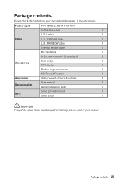
It should contain: Motherboard MPG X570S CARBON MAX WIFI SATA 6Gb/s cable 2 LED Y cable 1 Cable LED JCORSAIR cable 1 LED JRAINBOW cable 1 Thermal sensor cable 1 Wi-Fi antenna 1 M.2 screw + standoff (2 sets/pack) 2 Case badge 1 Accessories MPG Sticker 1 Product registration card 1 MSI Reward Program 1 Application USB drive with drivers & utilities 1 User manual 1 Documentation Quick installation guide 1 Small screwdriver set 1 Gifts Small brush 1 ⚠⚠Important If any of your retailer. Package contents 25 Package contents Please check the ...
It should contain: Motherboard MPG X570S CARBON MAX WIFI SATA 6Gb/s cable 2 LED Y cable 1 Cable LED JCORSAIR cable 1 LED JRAINBOW cable 1 Thermal sensor cable 1 Wi-Fi antenna 1 M.2 screw + standoff (2 sets/pack) 2 Case badge 1 Accessories MPG Sticker 1 Product registration card 1 MSI Reward Program 1 Application USB drive with drivers & utilities 1 User manual 1 Documentation Quick installation guide 1 Small screwdriver set 1 Gifts Small brush 1 ⚠⚠Important If any of your retailer. Package contents 25 Package contents Please check the ...
User Manual
Page 27
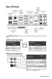
... ●● Rear Speaker Out ●●● Line-In/ Side Speaker Out ● Line-Out/ Front Speaker Out Mic In (●: connected, Blank: empty) Rear I /O Panel PS/2 Mouse/ Keyboard USB 3.2 Gen 2 (10Gbps) Clear CMOS Type-A button Wi-Fi Antenna connectors USB 3.2 Gen 2 (10Gbps) Type-A Audio Ports 2.5Gbps LAN Flash BIOS USB 2.0 Button Type-A Flash BIOS Port USB 3.2 Gen 1 (5Gbps) Type-A Optical USB 3.2 S/PDIF-Out Gen 2 (10Gbps) Type-C ∙∙ Flash BIOS Port/ Button - Rear I /O Panel 27 Please refer to page 58 for Updating BIOS with Flash BIOS Button.
... ●● Rear Speaker Out ●●● Line-In/ Side Speaker Out ● Line-Out/ Front Speaker Out Mic In (●: connected, Blank: empty) Rear I /O Panel PS/2 Mouse/ Keyboard USB 3.2 Gen 2 (10Gbps) Clear CMOS Type-A button Wi-Fi Antenna connectors USB 3.2 Gen 2 (10Gbps) Type-A Audio Ports 2.5Gbps LAN Flash BIOS USB 2.0 Button Type-A Flash BIOS Port USB 3.2 Gen 1 (5Gbps) Type-A Optical USB 3.2 S/PDIF-Out Gen 2 (10Gbps) Type-C ∙∙ Flash BIOS Port/ Button - Rear I /O Panel 27 Please refer to page 58 for Updating BIOS with Flash BIOS Button.
User Manual
Page 32
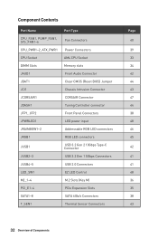
...JPWRLED1 JRAINBOW1~2 JRGB1 JUSB1 JUSB2~3 JUSB4~5 LED_SW1 M2_1~4 PCI_E1~4 SATA1~8 T_SEN1 Port Type Fan Connectors Power Connectors AM4 CPU Socket Memory slots Front Audio Connector Clear CMOS (Reset BIOS) Jumper Chassis Intrusion Connector CORSAIR Connector Tuning Controller connector Front Panel Connectors LED power input Addressable RGB LED connectors RGB LED connectors USB 3.2 Gen 2 10Gbps Type-C Connector USB 3.2 Gen 1 5Gbps Connectors USB 2.0 Connectors EZ LED Control M.2 Slots (Key M) PCIe Expansion Slots SATA 6Gb/s Connectors Thermal Sensor Connectors Page 40 39 33 34 42 44 43 47 44 38...
...JPWRLED1 JRAINBOW1~2 JRGB1 JUSB1 JUSB2~3 JUSB4~5 LED_SW1 M2_1~4 PCI_E1~4 SATA1~8 T_SEN1 Port Type Fan Connectors Power Connectors AM4 CPU Socket Memory slots Front Audio Connector Clear CMOS (Reset BIOS) Jumper Chassis Intrusion Connector CORSAIR Connector Tuning Controller connector Front Panel Connectors LED power input Addressable RGB LED connectors RGB LED connectors USB 3.2 Gen 2 10Gbps Type-C Connector USB 3.2 Gen 1 5Gbps Connectors USB 2.0 Connectors EZ LED Control M.2 Slots (Key M) PCIe Expansion Slots SATA 6Gb/s Connectors Thermal Sensor Connectors Page 40 39 33 34 42 44 43 47 44 38...
User Manual
Page 35
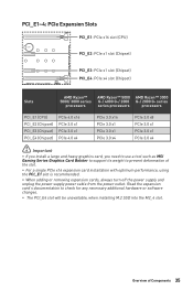
series series processors processors PCI_E1 (CPU) PCI_E2 (Chipset) PCI_E3 (Chipset) PCI_E4 (Chipset) PCIe 4.0 x16 PCIe 3.0 x1 PCIe 3.0 x1 PCIe 4.0 x4 PCIe 3.0 x16 PCIe 3.0 x1 PCIe 3.0 x1 PCIe 3.0 x4 PCIe 3.0 x8 PCIe 3.0 x1 PCIe 3.0 x1 PCIe 3.0 x4 ⚠⚠Important ∙∙If you install a large and heavy graphics card, you need to use a tool such as MSI Gaming Series Graphics Card Bolster to support its weight to check for any necessary additional hardware or software changes. ∙∙ The PCI_E4 slot will be...
series series processors processors PCI_E1 (CPU) PCI_E2 (Chipset) PCI_E3 (Chipset) PCI_E4 (Chipset) PCIe 4.0 x16 PCIe 3.0 x1 PCIe 3.0 x1 PCIe 4.0 x4 PCIe 3.0 x16 PCIe 3.0 x1 PCIe 3.0 x1 PCIe 3.0 x4 PCIe 3.0 x8 PCIe 3.0 x1 PCIe 3.0 x1 PCIe 3.0 x4 ⚠⚠Important ∙∙If you install a large and heavy graphics card, you need to use a tool such as MSI Gaming Series Graphics Card Bolster to support its weight to check for any necessary additional hardware or software changes. ∙∙ The PCI_E4 slot will be...
User Manual
Page 38
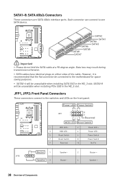
SATA1~8: SATA 6Gb/s Connectors These connectors are SATA 6Gb/s interface ports. Power LED Power Switch - -+ -- ++ JFP1 2 1 + 10 9 Reserved HDD LED Reset Switch 1 HDD LED + 2 3 HDD LED - 4 5 Reset Switch 6 7 Reset Switch 8 9 Reserved 10 Power LED + Power LED Power Switch Power Switch No Pin JFP2 1 + - + Buzzer 1 Speaker - 2 Speaker 3 Buzzer - 4 Buzzer + Speaker + 38 Overview of the cable. Each connector can connect to the motherboard for space saving purposes. ∙∙ SATA5-6 will be connected to one SATA device. SATA2 SATA1 SATA4 SATA3 SATA6...
SATA1~8: SATA 6Gb/s Connectors These connectors are SATA 6Gb/s interface ports. Power LED Power Switch - -+ -- ++ JFP1 2 1 + 10 9 Reserved HDD LED Reset Switch 1 HDD LED + 2 3 HDD LED - 4 5 Reset Switch 6 7 Reset Switch 8 9 Reserved 10 Power LED + Power LED Power Switch Power Switch No Pin JFP2 1 + - + Buzzer 1 Speaker - 2 Speaker 3 Buzzer - 4 Buzzer + Speaker + 38 Overview of the cable. Each connector can connect to the motherboard for space saving purposes. ∙∙ SATA5-6 will be connected to one SATA device. SATA2 SATA1 SATA4 SATA3 SATA6...
User Manual
Page 44
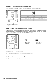
JDASH1 : Tuning Controller connector This connector is used to connect an optional Tuning Controller module. 26 15 1 No Pin 2 3 MCU_SMB_SCL_M 4 5 VCC5 6 NC MCU_SMB_SDA_M Ground JBAT1: Clear CMOS (Reset BIOS) Jumper There is CMOS memory onboard that is external powered from JBAT1. 4. If you want to clear the system configuration, set the jumper to short JBAT1 for about 5-10 seconds. 3. Power off the computer and unplug the power cord 2. Remove the jumper cap from a battery located on the computer. 44...
JDASH1 : Tuning Controller connector This connector is used to connect an optional Tuning Controller module. 26 15 1 No Pin 2 3 MCU_SMB_SCL_M 4 5 VCC5 6 NC MCU_SMB_SDA_M Ground JBAT1: Clear CMOS (Reset BIOS) Jumper There is CMOS memory onboard that is external powered from JBAT1. 4. If you want to clear the system configuration, set the jumper to short JBAT1 for about 5-10 seconds. 3. Power off the computer and unplug the power cord 2. Remove the jumper cap from a battery located on the computer. 44...
User Manual
Page 46
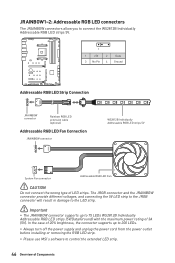
... JRAINBOW connector provide different voltages, and connecting the 5V LED strip to the JRGB connector will result in damage to the LED strip. ⚠⚠Important ∙∙The JRAINBOW connector supports up to 200 LEDs. ∙∙Always turn off the power supply and unplug the power cord from the power outlet before installing or removing the RGB LED strip. ∙∙Please use MSI's software to 75 LEDs WS2812B...
... JRAINBOW connector provide different voltages, and connecting the 5V LED strip to the JRGB connector will result in damage to the LED strip. ⚠⚠Important ∙∙The JRAINBOW connector supports up to 200 LEDs. ∙∙Always turn off the power supply and unplug the power cord from the power outlet before installing or removing the RGB LED strip. ∙∙Please use MSI's software to 75 LEDs WS2812B...
User Manual
Page 50
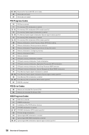
... specific) DXE IPL is started PEI Error Codes 4B Memory not installed (For Summit CPU) E0 Memory not installed (For Bristol CPU) DXE Progress Codes 60 61 62 63 64 - 67 68 69 6A 6B - 6F DXE Core is started NVRAM initialization Installation of Components Application Processor(s) (AP) initialization CPU post-memory initialization. Configuring memory Memory initialization (other) Memory Installed CPU post-memory initialization is started Pre-memory PCH initialization (PCH module specific) Memory initialization. Boot Strap Processor (BSP) selection CPU post-memory initialization. Serial...
... specific) DXE IPL is started PEI Error Codes 4B Memory not installed (For Summit CPU) E0 Memory not installed (For Bristol CPU) DXE Progress Codes 60 61 62 63 64 - 67 68 69 6A 6B - 6F DXE Core is started NVRAM initialization Installation of Components Application Processor(s) (AP) initialization CPU post-memory initialization. Configuring memory Memory initialization (other) Memory Installed CPU post-memory initialization is started Pre-memory PCH initialization (PCH module specific) Memory initialization. Boot Strap Processor (BSP) selection CPU post-memory initialization. Serial...
User Manual
Page 51
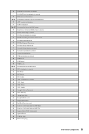
... is started PCI Bus initialization is started PCI Bus Hot Plug Controller Initialization PCI Bus Enumeration 32 PCI Bus Request Resources PCI Bus Assign Resources Console Output devices connect Console input devices connect Super IO Initialization USB initialization is started USB Reset USB Detect USB Enable Reserved for future AMI codes IDE initialization is started IDE Reset IDE Detect IDE Enable SCSI initialization is started SCSI Reset SCSI Detect SCSI Enable Setup Verifying Password Start of Setup Setup Input Wait Ready To Boot event Legacy Boot event Exit Boot Services event Runtime Set...
... is started PCI Bus initialization is started PCI Bus Hot Plug Controller Initialization PCI Bus Enumeration 32 PCI Bus Request Resources PCI Bus Assign Resources Console Output devices connect Console input devices connect Super IO Initialization USB initialization is started USB Reset USB Detect USB Enable Reserved for future AMI codes IDE initialization is started IDE Reset IDE Detect IDE Enable SCSI initialization is started SCSI Reset SCSI Detect SCSI Enable Setup Verifying Password Start of Setup Setup Input Wait Ready To Boot event Legacy Boot event Exit Boot Services event Runtime Set...
User Manual
Page 52
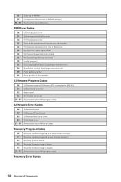
... Recovery firmware image is called by user (Forced recovery) Recovery process started Recovery firmware image is found D8 Invalid password D9 Error loading Boot Option (LoadImage returned error) DA Boot Option is failed (StartImage returned error) DB Flash update is failed DC Reset protocol is not available S3 Resume Progress Codes E0 E1 E2 E3 E4 - E7 S3 Resume is stared (S3 Resume PPI is loaded Reserved for Legacy Option ROM D6 No Console Output Devices...
... Recovery firmware image is called by user (Forced recovery) Recovery process started Recovery firmware image is found D8 Invalid password D9 Error loading Boot Option (LoadImage returned error) DA Boot Option is failed (StartImage returned error) DB Flash update is failed DC Reset protocol is not available S3 Resume Progress Codes E0 E1 E2 E3 E4 - E7 S3 Resume is stared (S3 Resume PPI is loaded Reserved for Legacy Option ROM D6 No Console Output Devices...
User Manual
Page 54
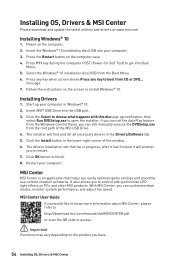
... Boot Menu. 5. Restart your computer in Windows® 10. 2. Press F11 key during the computer POST (Power-On Self Test) to finish. 8. Installing Drivers 1. The installer will prompt you easily optimize game settings and smoothly use content creation softwares. MSI Center User Guide If you would like to know more information about MSI Center, please refer to http://download.msi.com/manual/mb/MSICENTER.pdf or scan the QR code to access...
... Boot Menu. 5. Restart your computer in Windows® 10. 2. Press F11 key during the computer POST (Power-On Self Test) to finish. 8. Installing Drivers 1. The installer will prompt you easily optimize game settings and smoothly use content creation softwares. MSI Center User Guide If you would like to know more information about MSI Center, please refer to http://download.msi.com/manual/mb/MSICENTER.pdf or scan the QR code to access...
User Manual
Page 57
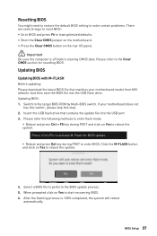
... the BIOS file into the USB port. 3. Switch to perform the BIOS update process. 5. Updating BIOS Updating BIOS with M-FLASH Before updating: Please download the latest BIOS file that contains the update file into the USB flash drive. Resetting BIOS You might need to restore the default BIOS setting to solve certain problems. There are several ways to reset BIOS: ∙∙Go to BIOS and press F6 to load optimized defaults. ∙∙Short the Clear CMOS jumper on the motherboard. ∙∙Press the Clear CMOS button on...
... the BIOS file into the USB port. 3. Switch to perform the BIOS update process. 5. Updating BIOS Updating BIOS with M-FLASH Before updating: Please download the latest BIOS file that contains the update file into the USB flash drive. Resetting BIOS You might need to restore the default BIOS setting to solve certain problems. There are several ways to reset BIOS: ∙∙Go to BIOS and press F6 to load optimized defaults. ∙∙Short the Clear CMOS jumper on the motherboard. ∙∙Press the Clear CMOS button on...
User Manual
Page 58
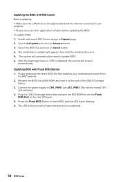
... will appear, then click the Install button on the rear I/O panel. 5. Press the Flash BIOS Button to Support page. 2. To update BIOS: 1. Please download the latest BIOS file that contains the MSI.ROM file into the Flash BIOS Port on it to update BIOS. 6. Select Live Update and click on Install button. 4. Updating the BIOS with Flash BIOS Button 1. The LED will automatically restart to the root of the USB 2.0 storage device. 3. Rename the BIOS file to install CPU and memory.) 4. Connect the power supply to CPU_PWR1 and ATX_PWR1. (No...
... will appear, then click the Install button on the rear I/O panel. 5. Press the Flash BIOS Button to Support page. 2. To update BIOS: 1. Please download the latest BIOS file that contains the MSI.ROM file into the Flash BIOS Port on it to update BIOS. 6. Select Live Update and click on Install button. 4. Updating the BIOS with Flash BIOS Button 1. The LED will automatically restart to the root of the USB 2.0 storage device. 3. Rename the BIOS file to install CPU and memory.) 4. Connect the power supply to CPU_PWR1 and ATX_PWR1. (No...
User Manual
Page 60
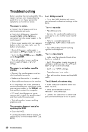
... 3 long beeps are heard, remove all ATX power connectors like ATX_PWR1, CPU_PWR1 are connected from the power supply to the motherboard? ∙∙Some power supply units have a power button on the rear side, make sure the LAN port LEDs are heard, remove and reinstall the graphics card and then restart the computer. ∙∙Test with another known working LAN cable. The computer does not boot after updating the BIOS ∙∙Clear the CMOS. ∙∙Use...
... 3 long beeps are heard, remove all ATX power connectors like ATX_PWR1, CPU_PWR1 are connected from the power supply to the motherboard? ∙∙Some power supply units have a power button on the rear side, make sure the LAN port LEDs are heard, remove and reinstall the graphics card and then restart the computer. ∙∙Test with another known working LAN cable. The computer does not boot after updating the BIOS ∙∙Clear the CMOS. ∙∙Use...
User Manual
Page 64
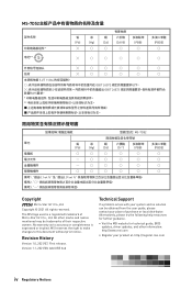
...Version 1.0, 2021/07, First release. No warranty as to this document without prior notice. Alternatively, please try the following help resources for further guidance. •• Visit the MSI website for technical guide, BIOS updates, driver updates, and other marks and names mentioned may be obtained from the user guide...: http://www.msi.com •• Register your place of their respective owners. "超出0.1 wt 0.01 wt 2 3 PBDE Copyright Micro-Star Int'l Co.,Ltd. Version 1.1, 2021/08, Add USB hub Technical Support If a problem arises with your...
...Version 1.0, 2021/07, First release. No warranty as to this document without prior notice. Alternatively, please try the following help resources for further guidance. •• Visit the MSI website for technical guide, BIOS updates, driver updates, and other marks and names mentioned may be obtained from the user guide...: http://www.msi.com •• Register your place of their respective owners. "超出0.1 wt 0.01 wt 2 3 PBDE Copyright Micro-Star Int'l Co.,Ltd. Version 1.1, 2021/08, Add USB hub Technical Support If a problem arises with your...


