User Manual
Page 1
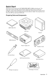
... demonstration diagrams about how to the URL by scanning the QR code. Preparing Tools and Components AMD® AM4 CPU CPU Fan DDR4 Memory Power Supply Unit Chassis Graphics Card Thermal Paste SATA Hard Disk Drive SATA DVD Drive Phillips Screwdriver A Package of the installations also provide video demonstrations. Please link to the URL to watch it with the web browser on your computer. Quick Start Thank you for purchasing the MSI® MEG X570S UNIFY-X MAX motherboard.
... demonstration diagrams about how to the URL by scanning the QR code. Preparing Tools and Components AMD® AM4 CPU CPU Fan DDR4 Memory Power Supply Unit Chassis Graphics Card Thermal Paste SATA Hard Disk Drive SATA DVD Drive Phillips Screwdriver A Package of the installations also provide video demonstrations. Please link to the URL to watch it with the web browser on your computer. Quick Start Thank you for purchasing the MSI® MEG X570S UNIFY-X MAX motherboard.
User Manual
Page 14
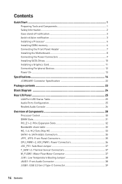
...Installing SATA Drives 10 Installing a Graphics Card 11 Connecting Peripheral Devices 12 Power On...13 Specifications...16 JCORSAIR1 Connector Specification 22 Package contents 23 Block Diagram ...24 Rear I/O Panel...25 LAN Port LED Status Table 25 Audio Ports Configuration 25 Realtek Audio Console 26 Overview of Components 28 Processor Socket 30 DIMM Slots...31 PCI_E1~2: PCIe Expansion Slots 32 Bandwidth share table 32 M2_1~6: M.2 Slots (Key M 33 SATA1~6: SATA 6Gb/s Connectors 35 JFP1, JFP2: Front Panel Connectors 35 CPU_PWR1~2, ATX_PWR1: Power Connectors 36 JOC_FS1: Safe Boot...
...Installing SATA Drives 10 Installing a Graphics Card 11 Connecting Peripheral Devices 12 Power On...13 Specifications...16 JCORSAIR1 Connector Specification 22 Package contents 23 Block Diagram ...24 Rear I/O Panel...25 LAN Port LED Status Table 25 Audio Ports Configuration 25 Realtek Audio Console 26 Overview of Components 28 Processor Socket 30 DIMM Slots...31 PCI_E1~2: PCIe Expansion Slots 32 Bandwidth share table 32 M2_1~6: M.2 Slots (Key M 33 SATA1~6: SATA 6Gb/s Connectors 35 JFP1, JFP2: Front Panel Connectors 35 CPU_PWR1~2, ATX_PWR1: Power Connectors 36 JOC_FS1: Safe Boot...
User Manual
Page 15
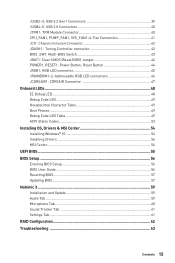
...: Multi-BIOS Switch 43 JBAT1: Clear CMOS (Reset BIOS) Jumper 44 POWER1, RESET1: Power Button, Reset Button 44 JRGB1: RGB LED connector 45 JRAINBOW1~2: Addressable RGB LED connectors 46 JCORSAIR1: CORSAIR Connector 47 Onboard LEDs...48 EZ Debug LED...48 Debug Code LED...49 Hexadecimal Character Table 49 Boot Phases...49 Debug Code LED Table 49 ACPI States Codes 53 Installing OS, Drivers & MSI Center 54 Installing Windows® 10 54 Installing Drivers 54 MSI Center...54 UEFI BIOS...55 BIOS Setup...56 Entering BIOS Setup 56 BIOS User Guide...56 Resetting BIOS...57 Updating BIOS...57...
...: Multi-BIOS Switch 43 JBAT1: Clear CMOS (Reset BIOS) Jumper 44 POWER1, RESET1: Power Button, Reset Button 44 JRGB1: RGB LED connector 45 JRAINBOW1~2: Addressable RGB LED connectors 46 JCORSAIR1: CORSAIR Connector 47 Onboard LEDs...48 EZ Debug LED...48 Debug Code LED...49 Hexadecimal Character Table 49 Boot Phases...49 Debug Code LED Table 49 ACPI States Codes 53 Installing OS, Drivers & MSI Center 54 Installing Windows® 10 54 Installing Drivers 54 MSI Center...54 UEFI BIOS...55 BIOS Setup...56 Entering BIOS Setup 56 BIOS User Guide...56 Resetting BIOS...57 Updating BIOS...57...
User Manual
Page 18
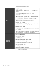
... USB 2.0 ports (3 Type-A ports on the back panel, 4 ports through the internal USB 2.0 connectors) ∙∙1x Clear CMOS Button ∙∙1x Flash BIOS Button ∙∙6x USB 2.0 ports ∙∙4x USB 3.2 Gen 1 5Gbps Type-A ports ∙∙3x USB 3.2 Gen 2 10Gbps Type-A ports ∙∙1x USB 3.2 Gen 2x2 20Gbps Type-C port ∙∙1x 2.5G LAN (RJ45) port ∙∙5x Audio jacks ∙∙1x Optical S/PDIF Out connector Continued on next page 18 Specifications
... USB 2.0 ports (3 Type-A ports on the back panel, 4 ports through the internal USB 2.0 connectors) ∙∙1x Clear CMOS Button ∙∙1x Flash BIOS Button ∙∙6x USB 2.0 ports ∙∙4x USB 3.2 Gen 1 5Gbps Type-A ports ∙∙3x USB 3.2 Gen 2 10Gbps Type-A ports ∙∙1x USB 3.2 Gen 2x2 20Gbps Type-C port ∙∙1x 2.5G LAN (RJ45) port ∙∙5x Audio jacks ∙∙1x Optical S/PDIF Out connector Continued on next page 18 Specifications
User Manual
Page 19
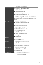
...Connectors Buttons Jumpers LED Features ∙∙1x 24-pin ATX main power connector ∙∙2x 8-pin ATX 12V power connector ∙∙6x SATA 6Gb/s connectors ∙∙6x M.2 slots (M-Key) ∙∙1x USB 3.2 Gen 2 10Gbps Type-C port ∙∙2x USB 3.2 Gen 1 5Gbps connector (supports additional 4 USB 3.2 Gen 1 5Gbps ports) ∙∙2x USB 2.0 connectors (supports additional 4 USB 2.0 ports) ∙∙1x 4-pin CPU fan connector ∙∙1x 4-pin water-pump fan connector ∙∙6x 4-pin system fan connectors ∙∙1x Front panel audio...
...Connectors Buttons Jumpers LED Features ∙∙1x 24-pin ATX main power connector ∙∙2x 8-pin ATX 12V power connector ∙∙6x SATA 6Gb/s connectors ∙∙6x M.2 slots (M-Key) ∙∙1x USB 3.2 Gen 2 10Gbps Type-C port ∙∙2x USB 3.2 Gen 1 5Gbps connector (supports additional 4 USB 3.2 Gen 1 5Gbps ports) ∙∙2x USB 2.0 connectors (supports additional 4 USB 2.0 ports) ∙∙1x 4-pin CPU fan connector ∙∙1x 4-pin water-pump fan connector ∙∙6x 4-pin system fan connectors ∙∙1x Front panel audio...
User Manual
Page 23
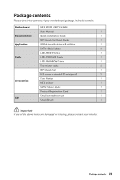
... are damaged or missing, please contact your motherboard package. It should contain: Motherboard MEG X570S UNIFY-X MAX User Manual 1 Documentation Quick Installation Guide 1 DIY Stands Set Quick Guide 1 Application USB drive with drivers & utilities 1 SATA 6Gb/s Cables 4 LED JRGB Y Cable 1 Cable LED JCORSAIR Cable 1 LED JRAINBOW Cable 1 Thermistor cable 2 DIY Stands Set 1 M.2 screw + standoff (2 sets/pack) 3 Case Badge 1 Accessories MEG sticker 1 SATA Cable Labels 1 Product Registration Card 1 Small screwdriver set 1 Gift Small Brush 1 ⚠⚠...
... are damaged or missing, please contact your motherboard package. It should contain: Motherboard MEG X570S UNIFY-X MAX User Manual 1 Documentation Quick Installation Guide 1 DIY Stands Set Quick Guide 1 Application USB drive with drivers & utilities 1 SATA 6Gb/s Cables 4 LED JRGB Y Cable 1 Cable LED JCORSAIR Cable 1 LED JRAINBOW Cable 1 Thermistor cable 2 DIY Stands Set 1 M.2 screw + standoff (2 sets/pack) 3 Case Badge 1 Accessories MEG sticker 1 SATA Cable Labels 1 Product Registration Card 1 Small screwdriver set 1 Gift Small Brush 1 ⚠⚠...
User Manual
Page 31
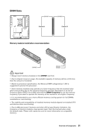
... insert memory modules in the DIMMB1 slot first. ∙∙Due to chipset resource usage, the available capacity of memory will be a little less than the amount of installed. ∙∙Based on processor specification, the Memory DIMM voltage below 1.35V is recommended to use a more information on installed CPU and devices when overclocking. ∙∙Due to AM4 processor/ memory controller official specification limitation, the frequency of memory modules...
... insert memory modules in the DIMMB1 slot first. ∙∙Due to chipset resource usage, the available capacity of memory will be a little less than the amount of installed. ∙∙Based on processor specification, the Memory DIMM voltage below 1.35V is recommended to use a more information on installed CPU and devices when overclocking. ∙∙Due to AM4 processor/ memory controller official specification limitation, the frequency of memory modules...
User Manual
Page 32
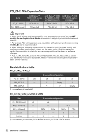
... or removing expansion cards, always turn off the power supply and unplug the power supply power cable from the power outlet. series processors PCIe 3.0 x8 PCIe 3.0 x8 ⚠⚠Important ∙∙If you install a large and heavy graphics card, you need to use a tool such as MSI Gaming Series Graphics Card Bolster to support its weight to check for more details. PCI_E1~2: PCIe Expansion Slots Slots PCI_E1 (CPU) PCI_E2 (Chipset) AMD Ryzen™ 5000/ 3000 series processors PCIe 4.0 x16 PCIe 4.0 x8 AMD Ryzen...
... or removing expansion cards, always turn off the power supply and unplug the power supply power cable from the power outlet. series processors PCIe 3.0 x8 PCIe 3.0 x8 ⚠⚠Important ∙∙If you install a large and heavy graphics card, you need to use a tool such as MSI Gaming Series Graphics Card Bolster to support its weight to check for more details. PCI_E1~2: PCIe Expansion Slots Slots PCI_E1 (CPU) PCI_E2 (Chipset) AMD Ryzen™ 5000/ 3000 series processors PCIe 4.0 x16 PCIe 4.0 x8 AMD Ryzen...
User Manual
Page 44
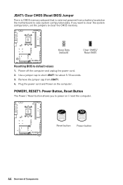
... Resetting BIOS to clear the CMOS memory. Use a jumper cap to power on / reset the computer. Reset Reset button Power button 44 Overview of Components POWER1, RESET1: Power Button, Reset Button The Power / Reset button allows you want to clear the system configuration, set the jumpers to default values 1. Plug the power cord and Power on the motherboard to save system configuration data. Power off the computer and unplug the power cord. 2. Remove the jumper cap from a battery located on the computer. JBAT1: Clear CMOS (Reset BIOS) Jumper There is CMOS memory onboard...
... Resetting BIOS to clear the CMOS memory. Use a jumper cap to power on / reset the computer. Reset Reset button Power button 44 Overview of Components POWER1, RESET1: Power Button, Reset Button The Power / Reset button allows you want to clear the system configuration, set the jumpers to default values 1. Plug the power cord and Power on the motherboard to save system configuration data. Power off the computer and unplug the power cord. 2. Remove the jumper cap from a battery located on the computer. JBAT1: Clear CMOS (Reset BIOS) Jumper There is CMOS memory onboard...
User Manual
Page 46
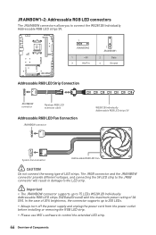
... JRAINBOW connector supports up to 200 LEDs. ∙∙Always turn off the power supply and unplug the power cord from the power outlet before installing or removing the RGB LED strip. ∙∙Please use MSI's software to 75 LEDs WS2812B Individually Addressable RGB LED strips (5V/Data/Ground) with the maximum power rating of LED strips. In the case of 20% brightness, the connector supports up to control the extended LED...
... JRAINBOW connector supports up to 200 LEDs. ∙∙Always turn off the power supply and unplug the power cord from the power outlet before installing or removing the RGB LED strip. ∙∙Please use MSI's software to 75 LEDs WS2812B Individually Addressable RGB LED strips (5V/Data/Ground) with the maximum power rating of LED strips. In the case of 20% brightness, the connector supports up to control the extended LED...
User Manual
Page 50
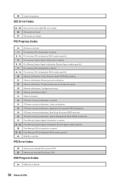
... started 38 - 3A Post-Memory System Agent initialization (System Agent module specific) 3B Post-Memory PCH initialization is started 3C - 3E Post-Memory PCH initialization (PCH module specific) 4F DXE IPL is started PEI Error Codes 4B Memory not installed (For Summit CPU) E0 Memory not installed (For Bristol CPU) DXE Progress Codes 60 DXE Core is started 33 CPU post-memory initialization. Application Processor(s) (AP) initialization 35 CPU post-memory initialization. Configuring memory 2F Memory initialization (other) 31 Memory Installed 32 CPU post-memory initialization is started...
... started 38 - 3A Post-Memory System Agent initialization (System Agent module specific) 3B Post-Memory PCH initialization is started 3C - 3E Post-Memory PCH initialization (PCH module specific) 4F DXE IPL is started PEI Error Codes 4B Memory not installed (For Summit CPU) E0 Memory not installed (For Bristol CPU) DXE Progress Codes 60 DXE Core is started 33 CPU post-memory initialization. Application Processor(s) (AP) initialization 35 CPU post-memory initialization. Configuring memory 2F Memory initialization (other) 31 Memory Installed 32 CPU post-memory initialization is started...
User Manual
Page 51
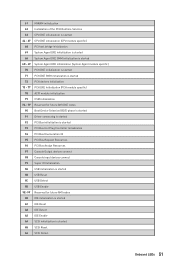
... PCI Bus Hot Plug Controller Initialization 94 PCI Bus Enumeration 32 95 PCI Bus Request Resources 96 PCI Bus Assign Resources 97 Console Output devices connect 98 Console input devices connect 99 Super IO Initialization 9A USB initialization is started 9B USB Reset 9C USB Detect 9D USB Enable 9E -9F Reserved for future AMI codes A0 IDE initialization is started A1 IDE Reset A2 IDE Detect A3 IDE Enable A4 SCSI initialization is started A5 SCSI Reset A6 SCSI Detect Onboard LEDs...
... PCI Bus Hot Plug Controller Initialization 94 PCI Bus Enumeration 32 95 PCI Bus Request Resources 96 PCI Bus Assign Resources 97 Console Output devices connect 98 Console input devices connect 99 Super IO Initialization 9A USB initialization is started 9B USB Reset 9C USB Detect 9D USB Enable 9E -9F Reserved for future AMI codes A0 IDE initialization is started A1 IDE Reset A2 IDE Detect A3 IDE Enable A4 SCSI initialization is started A5 SCSI Reset A6 SCSI Detect Onboard LEDs...
User Manual
Page 52
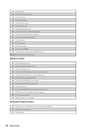
... SCSI Enable A8 Setup Verifying Password A9 Start of Setup AB Setup Input Wait AD Ready To Boot event AE Legacy Boot event AF Exit Boot Services event B0 Runtime Set Virtual Address MAP Begin B1 Runtime Set Virtual Address MAP End B2 Legacy Option ROM Initialization B3 System Reset B4 USB hot plug B5 PCI bus hot plug B6 Clean-up of NVRAM B7 Configuration Reset (reset of the Architectural Protocols are found D8 Invalid password D9 Error loading Boot Option...
... SCSI Enable A8 Setup Verifying Password A9 Start of Setup AB Setup Input Wait AD Ready To Boot event AE Legacy Boot event AF Exit Boot Services event B0 Runtime Set Virtual Address MAP Begin B1 Runtime Set Virtual Address MAP End B2 Legacy Option ROM Initialization B3 System Reset B4 USB hot plug B5 PCI bus hot plug B6 Clean-up of NVRAM B7 Configuration Reset (reset of the Architectural Protocols are found D8 Invalid password D9 Error loading Boot Option...
User Manual
Page 54
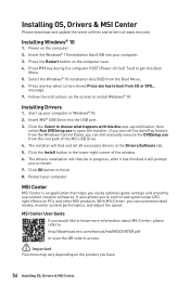
... Windows Control Panel, you can customize ideal modes, monitor system performance, and adjust fan speed. Power on the computer case. 4. The installer will prompt you to restart. 7. Insert MSI® USB Drive into Boot Menu. 5. Insert the Windows® 10 installation disc/USB into your computer. Press any key when screen shows Press any key to finish. 8. Click OK button to boot from the Boot Menu. 6. Restart your computer. 3. Installing OS, Drivers & MSI Center Please download and update the latest utilities...
... Windows Control Panel, you can customize ideal modes, monitor system performance, and adjust fan speed. Power on the computer case. 4. The installer will prompt you to restart. 7. Insert MSI® USB Drive into Boot Menu. 5. Insert the Windows® 10 installation disc/USB into your computer. Press any key when screen shows Press any key to finish. 8. Click OK button to boot from the Boot Menu. 6. Restart your computer. 3. Installing OS, Drivers & MSI Center Please download and update the latest utilities...
User Manual
Page 56
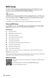
... also refer to access. 56 BIOS Setup Select between Advanced mode and EZ mode F8: Load Overclocking Profile F9: Save Overclocking Profile F10: Save Change and Reset* F12: Take a screenshot and save it provides the modification information. Function key F1: General Help list F2: Add/ Remove a favorite item F3: Enter Favorites menu F4: Enter CPU Specifications menu F5: Enter Memory-Z menu F6: Load optimized defaults F7: Switch between Yes or No to USB flash drive (FAT/ FAT32 format...
... also refer to access. 56 BIOS Setup Select between Advanced mode and EZ mode F8: Load Overclocking Profile F9: Save Overclocking Profile F10: Save Change and Reset* F12: Take a screenshot and save it provides the modification information. Function key F1: General Help list F2: Add/ Remove a favorite item F3: Enter Favorites menu F4: Enter CPU Specifications menu F5: Enter Memory-Z menu F6: Load optimized defaults F7: Switch between Yes or No to USB flash drive (FAT/ FAT32 format...
User Manual
Page 57
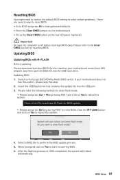
... reboot automatically. Updating BIOS Updating BIOS with M-FLASH Before updating: Please download the latest BIOS file that contains the update file into the USB flash drive. BIOS Setup 57 Resetting BIOS You might need to restore the default BIOS setting to solve certain problems. There are several ways to reset BIOS: ∙∙Go to BIOS and press F6 to load optimized defaults. ∙∙Short the Clear CMOS jumper on the motherboard. ∙∙Press the Clear CMOS button on Yes to start recovering BIOS. 6. Please...
... reboot automatically. Updating BIOS Updating BIOS with M-FLASH Before updating: Please download the latest BIOS file that contains the update file into the USB flash drive. BIOS Setup 57 Resetting BIOS You might need to restore the default BIOS setting to solve certain problems. There are several ways to reset BIOS: ∙∙Go to BIOS and press F6 to load optimized defaults. ∙∙Short the Clear CMOS jumper on the motherboard. ∙∙Press the Clear CMOS button on Yes to start recovering BIOS. 6. Please...
User Manual
Page 58
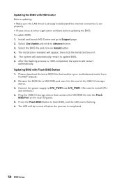
... the MSI.ROM file into the Flash BIOS Port on it to MSI.ROM, and save it . 5. Press the Flash BIOS Button to Support page. 2. Plug the USB 2.0 storage device that matches your motherboard model from the MSI® website. 2. Select Live Update and click on Install button. 4. Connect the power supply to CPU_PWR1 and ATX_PWR1. (No need to update BIOS. 6. Updating the BIOS with Flash BIOS Button 1. After the flashing process is 100% completed, the system will automatically restart to install CPU and memory.) 4. To update BIOS: 1.
... the MSI.ROM file into the Flash BIOS Port on it to MSI.ROM, and save it . 5. Press the Flash BIOS Button to Support page. 2. Plug the USB 2.0 storage device that matches your motherboard model from the MSI® website. 2. Select Live Update and click on Install button. 4. Connect the power supply to CPU_PWR1 and ATX_PWR1. (No need to update BIOS. 6. Updating the BIOS with Flash BIOS Button 1. After the flashing process is 100% completed, the system will automatically restart to install CPU and memory.) 4. To update BIOS: 1.
User Manual
Page 59
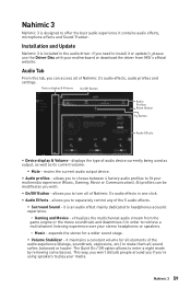
... separately control any of Nahimic 3's audio effects in one click. ∙∙ Audio Effects - If you 're using speakers to play your multimedia experience (Music, Gaming, Movie or Communication). Audio Tab From this tab, you to turn all of audio device currently being used as output, as well as you to enter a night mode by removing some basses. Device display & Volume On/Off Button Audio Profiles Reset Button Try Button Audio...
... separately control any of Nahimic 3's audio effects in one click. ∙∙ Audio Effects - If you 're using speakers to play your multimedia experience (Music, Gaming, Movie or Communication). Audio Tab From this tab, you to turn all of audio device currently being used as output, as well as you to enter a night mode by removing some basses. Device display & Volume On/Off Button Audio Profiles Reset Button Try Button Audio...
User Manual
Page 63
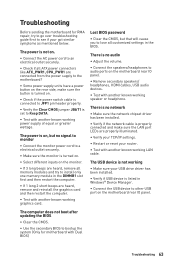
... working LAN cable. There is turned on. ∙∙Select different inputs on the motherboard rear IO panel. The power is on, but that will cause you to other USB port on the monitor. ∙∙If 3 long beeps are heard, remove all memory modules and try to go over troubleshooting guide first to see if your USB drive driver has been installed. ∙∙Verify if USB device is listed in Windows® Device...
... working LAN cable. There is turned on. ∙∙Select different inputs on the motherboard rear IO panel. The power is on, but that will cause you to other USB port on the monitor. ∙∙If 3 long beeps are heard, remove all memory modules and try to go over troubleshooting guide first to see if your USB drive driver has been installed. ∙∙Verify if USB device is listed in Windows® Device...
User Manual
Page 68
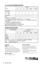
The MSI logo used is expressed or implied. Alternatively, please try the following help resources for technical guide, BIOS updates, driver updates, and other marks and names mentioned may be obtained from the user guide, please contact your product at: http://register.msi.com iv Regulatory Notices MS-7D51 铅 汞 镉 ... distributor. Technical Support If a problem arises with your system and no solution can be trademarks of Micro-Star Int'l Co., Ltd. yy Visit the MSI website for further guidance. MSI reserves the right to make changes to accuracy or...
The MSI logo used is expressed or implied. Alternatively, please try the following help resources for technical guide, BIOS updates, driver updates, and other marks and names mentioned may be obtained from the user guide, please contact your product at: http://register.msi.com iv Regulatory Notices MS-7D51 铅 汞 镉 ... distributor. Technical Support If a problem arises with your system and no solution can be trademarks of Micro-Star Int'l Co., Ltd. yy Visit the MSI website for further guidance. MSI reserves the right to make changes to accuracy or...


