User Manual
Page 1
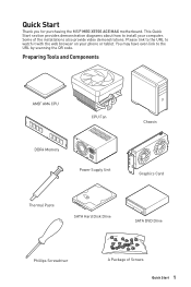
... link to install your phone or tablet. Quick Start Thank you for purchasing the MSI® MEG X570S ACE MAX motherboard. Some of Screws Quick Start 1 Please link to the URL to watch it with the web browser on your computer. Preparing Tools and Components AMD® AM4 CPU CPU Fan DDR4 Memory Power Supply Unit Chassis Graphics Card Thermal Paste SATA Hard Disk Drive SATA DVD Drive Phillips Screwdriver A Package of the installations also provide video demonstrations.
... link to install your phone or tablet. Quick Start Thank you for purchasing the MSI® MEG X570S ACE MAX motherboard. Some of Screws Quick Start 1 Please link to the URL to watch it with the web browser on your computer. Preparing Tools and Components AMD® AM4 CPU CPU Fan DDR4 Memory Power Supply Unit Chassis Graphics Card Thermal Paste SATA Hard Disk Drive SATA DVD Drive Phillips Screwdriver A Package of the installations also provide video demonstrations.
User Manual
Page 14
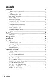
...Front Panel Header 7 Installing the Motherboard 8 Connecting the Power Connectors 9 Installing SATA Drives 10 Installing a Graphics Card 11 Connecting Peripheral Devices 12 Power On...13 Specifications...17 JCORSAIR1 Connector Specification 24 Package contents 25 Block Diagram ...26 Rear I/O Panel...27 LAN Port LED Status Table 27 Audio Ports Configuration 27 Realtek Audio Console 28 Installing Antennas 30 Overview of Components 31 Processor Socket 33 DIMM Slots...34 PCI_E1~4: PCIe Expansion Slots 35 PCIe bandwidth table 35 Bandwidth share table 36 M2_1~4: M.2 Slots (Key M 38...
...Front Panel Header 7 Installing the Motherboard 8 Connecting the Power Connectors 9 Installing SATA Drives 10 Installing a Graphics Card 11 Connecting Peripheral Devices 12 Power On...13 Specifications...17 JCORSAIR1 Connector Specification 24 Package contents 25 Block Diagram ...26 Rear I/O Panel...27 LAN Port LED Status Table 27 Audio Ports Configuration 27 Realtek Audio Console 28 Installing Antennas 30 Overview of Components 31 Processor Socket 33 DIMM Slots...34 PCI_E1~4: PCIe Expansion Slots 35 PCIe bandwidth table 35 Bandwidth share table 36 M2_1~4: M.2 Slots (Key M 38...
User Manual
Page 15
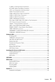
...: Clear CMOS (Reset BIOS) Jumper 50 POWER1, RESET1: Power Button, Reset Button 50 JRGB1: RGB LED connector 51 JRAINBOW1~2: Addressable RGB LED connectors 52 JCORSAIR1: CORSAIR Connector 53 Onboard LEDs...54 EZ Debug LED...54 JPWRLED1: LED power input 54 LED_SW1: EZ LED Control 54 Debug Code LED...55 Hexadecimal Character Table 55 Boot Phases...55 Debug Code LED Table 55 ACPI States Codes 59 Installing OS, Drivers & MSI Center 60 Installing Windows® 10 60 Installing Drivers 60 MSI Center...60 UEFI BIOS...61 BIOS Setup...62 Entering BIOS Setup 62 BIOS User Guide...62 Resetting...
...: Clear CMOS (Reset BIOS) Jumper 50 POWER1, RESET1: Power Button, Reset Button 50 JRGB1: RGB LED connector 51 JRAINBOW1~2: Addressable RGB LED connectors 52 JCORSAIR1: CORSAIR Connector 53 Onboard LEDs...54 EZ Debug LED...54 JPWRLED1: LED power input 54 LED_SW1: EZ LED Control 54 Debug Code LED...55 Hexadecimal Character Table 55 Boot Phases...55 Debug Code LED Table 55 ACPI States Codes 59 Installing OS, Drivers & MSI Center 60 Installing Windows® 10 60 Installing Drivers 60 MSI Center...60 UEFI BIOS...61 BIOS Setup...62 Entering BIOS Setup 62 BIOS User Guide...62 Resetting...
User Manual
Page 20
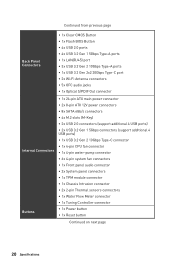
...PDIF Out connector Internal Connectors Buttons ∙∙1x 24-pin ATX main power connector ∙∙2x 8-pin ATX 12V power connectors ∙∙8x SATA 6Gb/s connectors ∙∙4x M.2 slots (M-Key) ∙∙2x USB 2.0 connectors (support additional 4 USB ports) ∙∙2x USB 3.2 Gen 1 5Gbps connectors (support additional 4 USB ports) ∙∙1x USB 3.2 Gen 2 10Gbps Type-C connector ∙∙1x 4-pin CPU fan connector ∙∙1x 4-pin water-pump connector ∙∙6x 4-pin system fan connectors ∙∙1x Front panel audio connector...
...PDIF Out connector Internal Connectors Buttons ∙∙1x 24-pin ATX main power connector ∙∙2x 8-pin ATX 12V power connectors ∙∙8x SATA 6Gb/s connectors ∙∙4x M.2 slots (M-Key) ∙∙2x USB 2.0 connectors (support additional 4 USB ports) ∙∙2x USB 3.2 Gen 1 5Gbps connectors (support additional 4 USB ports) ∙∙1x USB 3.2 Gen 2 10Gbps Type-C connector ∙∙1x 4-pin CPU fan connector ∙∙1x 4-pin water-pump connector ∙∙6x 4-pin system fan connectors ∙∙1x Front panel audio connector...

User Manual
Page 21
Jumpers LED Features I/O Controller Hardware Monitor Form Factor BIOS Features Software Continued from previous page ∙∙1x Clear CMOS jumper ∙∙1x Low temperature booting jumper ∙∙1x Safe Boot jumper ∙∙1x 4-pin RGB LED connector ∙∙2x 3-pin RAINBOW LED connectors ∙∙1x 3-pin CORSAIR connector ∙∙1x EZ LED Control switch ∙∙1x 2-Digit Debug Code LED ∙∙4x EZ Debug LEDs NUVOTON NCT6687D Controller Chip ∙∙CPU/ System/ Chipset temperature detection...
Jumpers LED Features I/O Controller Hardware Monitor Form Factor BIOS Features Software Continued from previous page ∙∙1x Clear CMOS jumper ∙∙1x Low temperature booting jumper ∙∙1x Safe Boot jumper ∙∙1x 4-pin RGB LED connector ∙∙2x 3-pin RAINBOW LED connectors ∙∙1x 3-pin CORSAIR connector ∙∙1x EZ LED Control switch ∙∙1x 2-Digit Debug Code LED ∙∙4x EZ Debug LEDs NUVOTON NCT6687D Controller Chip ∙∙CPU/ System/ Chipset temperature detection...
User Manual
Page 25
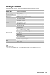
It should contain: Motherboard MEG X570S ACE MAX User Manual 1 Documentation Quick Installation Guide 1 Application USB drive with drivers & utilities 1 SATA 6Gb/s Cables 4 LED JRGB Y Cable 1 Cable LED JCORSAIR Cable 1 LED JRAINBOW Cable 1 Thermistor cable 2 Wi-Fi Antenna 1 M.2 XPANDER-Z GEN 4 S card 1 M.2 screw + standoff (2 sets/pack) 2 Accessories Case Badge 1 MEG sticker 1 SATA Cable Labels 1 Product Registration Card 1 Small screwdriver set 1 Gift Small Brush 1 ⚠⚠Important If any of your retailer. Package contents 25 Package ...
It should contain: Motherboard MEG X570S ACE MAX User Manual 1 Documentation Quick Installation Guide 1 Application USB drive with drivers & utilities 1 SATA 6Gb/s Cables 4 LED JRGB Y Cable 1 Cable LED JCORSAIR Cable 1 LED JRAINBOW Cable 1 Thermistor cable 2 Wi-Fi Antenna 1 M.2 XPANDER-Z GEN 4 S card 1 M.2 screw + standoff (2 sets/pack) 2 Accessories Case Badge 1 MEG sticker 1 SATA Cable Labels 1 Product Registration Card 1 Small screwdriver set 1 Gift Small Brush 1 ⚠⚠Important If any of your retailer. Package contents 25 Package ...
User Manual
Page 34
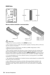
... than the marked value when overclocking due to the memory frequency operates dependent on installed CPU and devices when overclocking. ∙∙Due to BIOS and find the DRAM Frequency! Please refer www.msi.com for full DIMMs installation or overclocking. ∙∙The stability and compatibility of installed memory module depend on its Serial Presence Detect (SPD). DIMM Slots DIMMA1 DIMMB1 Channel A Channel B DIMMA2 Memory module installation recommendation DIMMB2 DIMMA2 DIMMA2...
... than the marked value when overclocking due to the memory frequency operates dependent on installed CPU and devices when overclocking. ∙∙Due to BIOS and find the DRAM Frequency! Please refer www.msi.com for full DIMMs installation or overclocking. ∙∙The stability and compatibility of installed memory module depend on its Serial Presence Detect (SPD). DIMM Slots DIMMA1 DIMMB1 Channel A Channel B DIMMA2 Memory module installation recommendation DIMMB2 DIMMA2 DIMMA2...
User Manual
Page 35
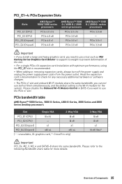
... same bandwidth. PCI_E1~4: PCIe Expansion Slots Slots PCI_E1 (CPU) PCI_E2 (CPU) PCI_E3 (Chipset) PCI_E4 (Chipset) AMD Ryzen™ 5000/ 3000 series processors PCIe 4.0 x16 PCIe 4.0 x8 PCIe 4.0 x1 PCIe 4.0 x8 AMD Ryzen™ 5000 G-/ 4000 G-/ 2000 series processors PCIe 3.0 x16 PCIe 3.0 x8 PCIe 3.0 x1 PCIe 3.0 x8 AMD Ryzen™ 3000 G-/ 2000 G- Please disable the Onboard Wi-Fi Module Control in BIOS if you can not use the PCIe x1 slot. Overview of them simultaneously, and the default setting is recommended. ∙...
... same bandwidth. PCI_E1~4: PCIe Expansion Slots Slots PCI_E1 (CPU) PCI_E2 (CPU) PCI_E3 (Chipset) PCI_E4 (Chipset) AMD Ryzen™ 5000/ 3000 series processors PCIe 4.0 x16 PCIe 4.0 x8 PCIe 4.0 x1 PCIe 4.0 x8 AMD Ryzen™ 5000 G-/ 4000 G-/ 2000 series processors PCIe 3.0 x16 PCIe 3.0 x8 PCIe 3.0 x1 PCIe 3.0 x8 AMD Ryzen™ 3000 G-/ 2000 G- Please disable the Onboard Wi-Fi Module Control in BIOS if you can not use the PCIe x1 slot. Overview of them simultaneously, and the default setting is recommended. ∙...

User Manual
Page 41
... set the fan duty cycle and the LED color of Components 41 Overview of the card in BIOS. 11 PCIE_PWR1 JCASE + JMB + JSMB 12 JFP1 2 1 13 HDD LED 14 JSMB1 + - Using the supplied JSMB cable to the power supply. 12. Use a screw to connect the JMB connector and JFP1's HDD pins (pin 1 & pin3). 14. Insert the card into the PCI_E2 slot. 10. Using the supplied HDD LED cable to secure the card. 10 9 PCI_E2 11. Connect the case's HDD LED cable...
... set the fan duty cycle and the LED color of Components 41 Overview of the card in BIOS. 11 PCIE_PWR1 JCASE + JMB + JSMB 12 JFP1 2 1 13 HDD LED 14 JSMB1 + - Using the supplied JSMB cable to the power supply. 12. Use a screw to connect the JMB connector and JFP1's HDD pins (pin 1 & pin3). 14. Insert the card into the PCI_E2 slot. 10. Using the supplied HDD LED cable to secure the card. 10 9 PCI_E2 11. Connect the case's HDD LED cable...
User Manual
Page 50
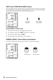
... computer and unplug the power cord. 2. POWER1, RESET1: Power Button, Reset Button The Power / Reset button allows you want to clear the system configuration, set the jumpers to default values 1. Use a jumper cap to power on / reset the computer. If you to short JBAT1 for about 5-10 seconds. 3. Keep Data (default) Clear CMOS/ Reset BIOS Resetting BIOS to clear the CMOS memory. JBAT1: Clear CMOS (Reset BIOS) Jumper There is CMOS memory onboard that is external powered from JBAT1. 4. Plug the power cord and Power on the motherboard to save system...
... computer and unplug the power cord. 2. POWER1, RESET1: Power Button, Reset Button The Power / Reset button allows you want to clear the system configuration, set the jumpers to default values 1. Use a jumper cap to power on / reset the computer. If you to short JBAT1 for about 5-10 seconds. 3. Keep Data (default) Clear CMOS/ Reset BIOS Resetting BIOS to clear the CMOS memory. JBAT1: Clear CMOS (Reset BIOS) Jumper There is CMOS memory onboard that is external powered from JBAT1. 4. Plug the power cord and Power on the motherboard to save system...
User Manual
Page 52
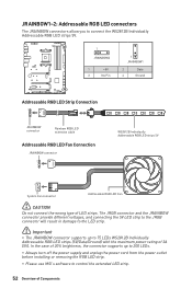
... JRAINBOW connector supports up to 200 LEDs. ∙∙Always turn off the power supply and unplug the power cord from the power outlet before installing or removing the RGB LED strip. ∙∙Please use MSI's software to control the extended LED strip. 52 Overview of Components JRAINBOW1~2: Addressable RGB LED connectors The JRAINBOW connectors allow you to connect the WS2812B Individually Addressable RGB LED strips 5V. 1 JRAINBOW2 1 +5V 3 No Pin...
... JRAINBOW connector supports up to 200 LEDs. ∙∙Always turn off the power supply and unplug the power cord from the power outlet before installing or removing the RGB LED strip. ∙∙Please use MSI's software to control the extended LED strip. 52 Overview of Components JRAINBOW1~2: Addressable RGB LED connectors The JRAINBOW connectors allow you to connect the WS2812B Individually Addressable RGB LED strips 5V. 1 JRAINBOW2 1 +5V 3 No Pin...
User Manual
Page 56
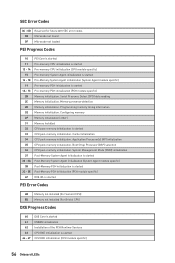
...Codes 10 PEI Core is started 11 Pre-memory CPU initialization is started 12 - 14 Pre-memory CPU initialization (CPU module specific) 15 Pre-memory System Agent initialization is started 16 - 18 Pre-Memory System Agent initialization (System Agent module specific) 19 Pre-memory PCH initialization is started CPU DXE initialization (CPU module specific) 56 Onboard LEDs Configuring memory 2F Memory initialization (other) 31 Memory Installed 32 CPU post-memory initialization is started 33 CPU post-memory initialization. Programming memory timing information 2E Memory initialization. Boot...
...Codes 10 PEI Core is started 11 Pre-memory CPU initialization is started 12 - 14 Pre-memory CPU initialization (CPU module specific) 15 Pre-memory System Agent initialization is started 16 - 18 Pre-Memory System Agent initialization (System Agent module specific) 19 Pre-memory PCH initialization is started CPU DXE initialization (CPU module specific) 56 Onboard LEDs Configuring memory 2F Memory initialization (other) 31 Memory Installed 32 CPU post-memory initialization is started 33 CPU post-memory initialization. Programming memory timing information 2E Memory initialization. Boot...
User Manual
Page 58
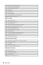
... Boot Script execution Video repost OS S3 wake vector call Reserved for future AMI codes DXE Error Codes D0 CPU initialization error D1 System Agent initialization error D2 PCH initialization error D3 Some of NVRAM settings) B8 - B0 Runtime Set Virtual Address MAP Begin B1 Runtime Set Virtual Address MAP End B2 Legacy Option ROM Initialization B3 System Reset B4 USB hot plug B5 PCI bus hot plug B6 Clean-up of NVRAM B7 Configuration Reset (reset...
... Boot Script execution Video repost OS S3 wake vector call Reserved for future AMI codes DXE Error Codes D0 CPU initialization error D1 System Agent initialization error D2 PCH initialization error D3 Some of NVRAM settings) B8 - B0 Runtime Set Virtual Address MAP Begin B1 Runtime Set Virtual Address MAP End B2 Legacy Option ROM Initialization B3 System Reset B4 USB hot plug B5 PCI bus hot plug B6 Clean-up of NVRAM B7 Configuration Reset (reset...
User Manual
Page 60
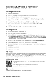
... Install button in the Drivers/Software tab. 5. Start up notification, then select Run DVDSetup.exe to get into the USB port. 3. If you turn off the AutoPlay feature from the Windows Control Panel, you would like to know more information about MSI Center, please refer to http://download.msi.com/manual/mb/MSICENTER.pdf or scan the QR code to install Windows® 10. Press F11 key during the computer POST (Power...
... Install button in the Drivers/Software tab. 5. Start up notification, then select Run DVDSetup.exe to get into the USB port. 3. If you turn off the AutoPlay feature from the Windows Control Panel, you would like to know more information about MSI Center, please refer to http://download.msi.com/manual/mb/MSICENTER.pdf or scan the QR code to install Windows® 10. Press F11 key during the computer POST (Power...
User Manual
Page 62
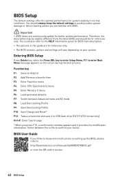
...;The BIOS screens, options and settings will vary depending on the screen during the boot process. BIOS Setup The default settings offer the optimal performance for system stability in this guide are continuously update for better system performance. Entering BIOS Setup Press Delete key, when the Press DEL key to enter Setup Menu, F11 to access. 62 BIOS Setup BIOS User Guide If you press F10, a confirmation window appears and it to the HELP information panel for BIOS item...
...;The BIOS screens, options and settings will vary depending on the screen during the boot process. BIOS Setup The default settings offer the optimal performance for system stability in this guide are continuously update for better system performance. Entering BIOS Setup Press Delete key, when the Press DEL key to enter Setup Menu, F11 to access. 62 BIOS Setup BIOS User Guide If you press F10, a confirmation window appears and it to the HELP information panel for BIOS item...
User Manual
Page 63
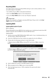
... to load optimized defaults. ∙∙Short the Clear CMOS jumper on the motherboard. ∙∙Press the Clear CMOS button on Yes to reboot the system. 4. Updating BIOS Updating BIOS with M-FLASH Before updating: Please download the latest BIOS file that contains the update file into the USB flash drive. Updating BIOS: 1. If your motherboard model from MSI website. After the flashing process is off before clearing CMOS data. Switch to perform the BIOS update process. 5. Click the M-FLASH button and click on the rear I/O panel. (optional) ⚠...
... to load optimized defaults. ∙∙Short the Clear CMOS jumper on the motherboard. ∙∙Press the Clear CMOS button on Yes to reboot the system. 4. Updating BIOS Updating BIOS with M-FLASH Before updating: Please download the latest BIOS file that contains the update file into the USB flash drive. Updating BIOS: 1. If your motherboard model from MSI website. After the flashing process is off before clearing CMOS data. Switch to perform the BIOS update process. 5. Click the M-FLASH button and click on the rear I/O panel. (optional) ⚠...
User Manual
Page 64
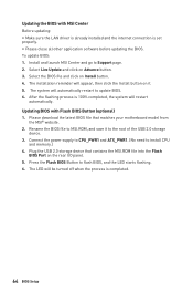
... LED starts flashing. 6. Updating BIOS with MSI Center Before updating: ∙∙Make sure the LAN driver is already installed and the internet connection is completed. 64 BIOS Setup Select Live Update and click on Install button. 4. After the flashing process is 100% completed, the system will be turned off when the process is set properly. ∙∙Please close all other application software before updating the BIOS. Plug the USB 2.0 storage device that matches your motherboard model...
... LED starts flashing. 6. Updating BIOS with MSI Center Before updating: ∙∙Make sure the LAN driver is already installed and the internet connection is completed. 64 BIOS Setup Select Live Update and click on Install button. 4. After the flashing process is 100% completed, the system will be turned off when the process is set properly. ∙∙Please close all other application software before updating the BIOS. Plug the USB 2.0 storage device that matches your motherboard model...
User Manual
Page 65
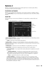
... use the Driver Disc with your multimedia experience (Music, Gaming, Movie or Communication). Nahimic 3 65 it contains audio effects, microphone effects and Sound Tracker. The Quiet On / Off option allows to enter a night mode by removing some basses. Nahimic 3 Nahimic 3 is designed to offer the best audio experience it is included in the audio driver. Installation and Update Nahimic 3 is an audio effect mainly dedicated...
... use the Driver Disc with your multimedia experience (Music, Gaming, Movie or Communication). Nahimic 3 65 it contains audio effects, microphone effects and Sound Tracker. The Quiet On / Off option allows to enter a night mode by removing some basses. Nahimic 3 Nahimic 3 is designed to offer the best audio experience it is included in the audio driver. Installation and Update Nahimic 3 is an audio effect mainly dedicated...

User Manual
Page 69
... known working power supply of equal or greater wattage. Troubleshooting Before sending the motherboard for motherboard with another known working LAN cable. The USB device is not working ∙∙Make sure your USB drive driver has been installed. ∙∙Verify if USB device is listed in Windows® Device Manager. ∙∙Connect the USB device to other USB port on . ∙∙Check if the power switch cable is connected to JFP1 pin header properly. ∙∙Verify the Clear CMOS jumper...
... known working power supply of equal or greater wattage. Troubleshooting Before sending the motherboard for motherboard with another known working LAN cable. The USB device is not working ∙∙Make sure your USB drive driver has been installed. ∙∙Verify if USB device is listed in Windows® Device Manager. ∙∙Connect the USB device to other USB port on . ∙∙Check if the power switch cable is connected to JFP1 pin header properly. ∙∙Verify the Clear CMOS jumper...
User Manual
Page 74
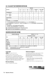
... prior notice. Technical Support If a problem arises with your system and no solution can be trademarks of Micro-Star Int'l Co., Ltd. yy Visit the MSI website for further guidance. Alternatively, please try the following help resources for technical guide, BIOS updates, driver updates, and other marks and names mentioned may be obtained from the user guide, please contact your...
... prior notice. Technical Support If a problem arises with your system and no solution can be trademarks of Micro-Star Int'l Co., Ltd. yy Visit the MSI website for further guidance. Alternatively, please try the following help resources for technical guide, BIOS updates, driver updates, and other marks and names mentioned may be obtained from the user guide, please contact your...


