User Guide
Page 2
...the properties of their respective owners. Award® is a registered trademark of American Megatrends Inc. Alternatively, please try the following help resources for FAQ, technical guide, BIOS updates, driver updates, and other countries. Trademarks All ...support.msi.com.tw/ ii AMD, Athlon™, Athlon™ XP, Thoroughbred™, and Duron™ are registered trademarks of Microsoft Corporation. Copyright Notice The material in this document, but no solution can be obtained from the user's manual, please contact your system and no guarantee is given as to make changes...
...the properties of their respective owners. Award® is a registered trademark of American Megatrends Inc. Alternatively, please try the following help resources for FAQ, technical guide, BIOS updates, driver updates, and other countries. Trademarks All ...support.msi.com.tw/ ii AMD, Athlon™, Athlon™ XP, Thoroughbred™, and Duron™ are registered trademarks of Microsoft Corporation. Copyright Notice The material in this document, but no solution can be obtained from the user's manual, please contact your system and no guarantee is given as to make changes...
User Guide
Page 8
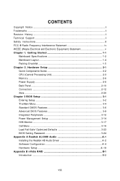
... v Chapter 1. Getting Started 1-1 Mainboard Specifications 1-2 Mainboard Layout 1-4 Packing Checklist 1-5 Chapter 2. Hardware Setup 2-1 Quick Components Guide 2-2 CPU (Central Processing Unit 2-3 Memory ...2-6 Power Supply ...2-8 Back Panel ...2-10 Connectors ...2-12 Slots ...2-20 Chapter 3 BIOS Setup 3-1 Entering Setup ...3-2 The Main Menu ...3-4 Standard CMOS Features 3-6 Advanced BIOS Features 3-9 Integrated Peripherals 3-12 Power Management Setup 3-14 H/W Monitor ...3-17 Cell Menu ...3-18 Load Fail-Safe/ Optimized Defaults 3-23 BIOS Setting Password 3-24 Appendix A Realtek...
... v Chapter 1. Getting Started 1-1 Mainboard Specifications 1-2 Mainboard Layout 1-4 Packing Checklist 1-5 Chapter 2. Hardware Setup 2-1 Quick Components Guide 2-2 CPU (Central Processing Unit 2-3 Memory ...2-6 Power Supply ...2-8 Back Panel ...2-10 Connectors ...2-12 Slots ...2-20 Chapter 3 BIOS Setup 3-1 Entering Setup ...3-2 The Main Menu ...3-4 Standard CMOS Features 3-6 Advanced BIOS Features 3-9 Integrated Peripherals 3-12 Power Management Setup 3-14 H/W Monitor ...3-17 Cell Menu ...3-18 Load Fail-Safe/ Optimized Defaults 3-23 BIOS Setting Password 3-24 Appendix A Realtek...
User Guide
Page 11
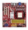
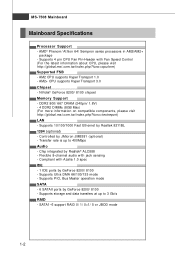
.../ 667 DRAM (240pin/ 1.8V) - 4 DDR2 DIMMs (8GB Max) (For more information on compatible components, please visit ht t p: / / gl oba l. Supports 4 pin CPU Fan Pin-Header with jack sensing - Controlled by GeForce 8200/ 8100 - AM2+ CPU supports Hyper Transport 3.0 Chipset - Supports PIO, Bus Master operation mode SATA - 6 SATAII ports by JMicron JMB381 (optional) - c om. p hp?f unc =t e s t re por t ) LAN - MS-7508 Mainboard Mainboard Specifications Processor Support - Transfer rate is up to 400Mbps Audio - Compliant with Azalia 1.0 spec IDE - 1 IDE ports by...
.../ 667 DRAM (240pin/ 1.8V) - 4 DDR2 DIMMs (8GB Max) (For more information on compatible components, please visit ht t p: / / gl oba l. Supports 4 pin CPU Fan Pin-Header with jack sensing - Controlled by GeForce 8200/ 8100 - AM2+ CPU supports Hyper Transport 3.0 Chipset - Supports PIO, Bus Master operation mode SATA - 6 SATAII ports by JMicron JMB381 (optional) - c om. p hp?f unc =t e s t re por t ) LAN - MS-7508 Mainboard Mainboard Specifications Processor Support - Transfer rate is up to 400Mbps Audio - Compliant with Azalia 1.0 spec IDE - 1 IDE ports by...

User Guide
Page 12
...Connectors Back panel - 1 PS/2 mouse port - 1 PS/2 keyboard port - 1 HDMI port (optional) - 1 DVI-D port (optional) - 1 VGA port - 1 1394 port (optional) - 1 LAN jack - 4 USB 2.0 ports - 6 flexible audio jacks On-Board Pinheaders - 2 USB 2.0 pinheaders - 1 1394 pinheader (optional) - 1 Front Panel Audio pinheader - 1 CD-in pinheader - 1 Serial port pinheader - 1 TPM Module pinheader (optional) - 1 SPDIF-out pinheader - 1 Chassis Intrusion pinheader TPM (optional) - Getting Started Floppy - 1 floppy port - Micro-ATX (24.4cm X 24.4 cm) Mounting - 8 mounting holes 1-3 Supports TPM Slots - 1 PCI...
...Connectors Back panel - 1 PS/2 mouse port - 1 PS/2 keyboard port - 1 HDMI port (optional) - 1 DVI-D port (optional) - 1 VGA port - 1 1394 port (optional) - 1 LAN jack - 4 USB 2.0 ports - 6 flexible audio jacks On-Board Pinheaders - 2 USB 2.0 pinheaders - 1 1394 pinheader (optional) - 1 Front Panel Audio pinheader - 1 CD-in pinheader - 1 Serial port pinheader - 1 TPM Module pinheader (optional) - 1 SPDIF-out pinheader - 1 Chassis Intrusion pinheader TPM (optional) - Getting Started Floppy - 1 floppy port - Micro-ATX (24.4cm X 24.4 cm) Mounting - 8 mounting holes 1-3 Supports TPM Slots - 1 PCI...
User Guide
Page 22
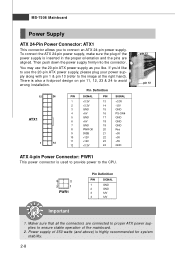
... 24 GND ATX 4-pin Power Connector: PWR1 This power connector is also a foolproof design on pin 11, 12, 23 & 24 to avoid wrong installation. MS-7508 Mainboard Power Supply ATX 24-Pin Power Connector: ATX1 This connector allows you to the CPU. 4 2 3 1 PWR1 Pin Definition PIN SIGNAL 1 GND 2 GND 3 12V 4 12V pin 13 pin 12 Important 1. You may use the 20-pin ATX power supply as you like to use the 20-pin ATX power supply, please plug your power supply along with pin 1 & pin 13...
... 24 GND ATX 4-pin Power Connector: PWR1 This power connector is also a foolproof design on pin 11, 12, 23 & 24 to avoid wrong installation. MS-7508 Mainboard Power Supply ATX 24-Pin Power Connector: ATX1 This connector allows you to the CPU. 4 2 3 1 PWR1 Pin Definition PIN SIGNAL 1 GND 2 GND 3 12V 4 12V pin 13 pin 12 Important 1. You may use the 20-pin ATX power supply as you like to use the 20-pin ATX power supply, please plug your power supply along with pin 1 & pin 13...

User Guide
Page 24
...-digital audio/video interface capable of the cable is properly connected to your monitor (refer to your monitor cable into the DVI-D connector, and make sure that the HDMI port has be connected before you to IEEE1394 devices. 2-10 It provides a high-speed digital interconnection between the computer and its display device. MS-7508 Mainboard Back Panel Mouse (optional) HDMI Port Keyboard VGA Port (optional) LAN 1394 Port Line-In RS-Out Line-Out CS-Out DVI-D Port (optional) USB Port USB Port...
...-digital audio/video interface capable of the cable is properly connected to your monitor (refer to your monitor cable into the DVI-D connector, and make sure that the HDMI port has be connected before you to IEEE1394 devices. 2-10 It provides a high-speed digital interconnection between the computer and its display device. MS-7508 Mainboard Back Panel Mouse (optional) HDMI Port Keyboard VGA Port (optional) LAN 1394 Port Line-In RS-Out Line-Out CS-Out DVI-D Port (optional) USB Port USB Port...

User Guide
Page 26
MS-7508 Mainboard Connectors Floppy Disk Drive Connector: FDD1 This connector supports 360KB, 720KB, 1.2MB, 1.44MB or 2.88MB floppy disk drive. FDD1 IDE Connector: IDE1 This connector supports IDE hard disk drives, optical disk drives and other IDE devices. Refer to master / slave mode by the vendors for jumper setting instructions. 2-12 IDE1 Important If you install two IDE devices on the same cable, you must configure the drives separately to IDE device's documentation supplied by setting jumpers.
MS-7508 Mainboard Connectors Floppy Disk Drive Connector: FDD1 This connector supports 360KB, 720KB, 1.2MB, 1.44MB or 2.88MB floppy disk drive. FDD1 IDE Connector: IDE1 This connector supports IDE hard disk drives, optical disk drives and other IDE devices. Refer to master / slave mode by the vendors for jumper setting instructions. 2-12 IDE1 Important If you install two IDE devices on the same cable, you must configure the drives separately to IDE device's documentation supplied by setting jumpers.
User Guide
Page 28
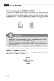
... actual CPU temperature. 3. CPUFAN1 supports fan control. You can install Dual Core Center utility that the red wire is Ground and should be connected to take advantage of the CPU fan control. Fan/heatsink with speed sensor to GND. GND +12V SENSOR CONTROL NC +12V GND CPUFAN1 SYSFAN1 Important 1. If the mainboard has a System Hardware Monitor chipset on-board, you must use a specially designed fan with 3 or 4 pins are both available for CPUFAN1. MS-7508 Mainboard Fan Power Connectors...
... actual CPU temperature. 3. CPUFAN1 supports fan control. You can install Dual Core Center utility that the red wire is Ground and should be connected to take advantage of the CPU fan control. Fan/heatsink with speed sensor to GND. GND +12V SENSOR CONTROL NC +12V GND CPUFAN1 SYSFAN1 Important 1. If the mainboard has a System Hardware Monitor chipset on-board, you must use a specially designed fan with 3 or 4 pins are both available for CPUFAN1. MS-7508 Mainboard Fan Power Connectors...

User Guide
Page 34
... rate. PCI Express x16 Slot PCI Express x1 Slot PCI (Peripheral Component Interconnect) Slot The PCI slot supports LAN card, SCSI card, USB card, and other add-on cards that comply with PCI specifications. 32-bit PCI Slot Important When adding or removing expansion cards, make sure that you unplug the power supply first. The PCI Express x 4 supports up to the PCI bus pins as jumpers, switches or BIOS configuration. PCI Interrupt Request Routing The IRQ, acronym of interrupt request line and pronounced I-R-Q, are typically connected to 2.0 GB...
... rate. PCI Express x16 Slot PCI Express x1 Slot PCI (Peripheral Component Interconnect) Slot The PCI slot supports LAN card, SCSI card, USB card, and other add-on cards that comply with PCI specifications. 32-bit PCI Slot Important When adding or removing expansion cards, make sure that you unplug the power supply first. The PCI Express x 4 supports up to the PCI bus pins as jumpers, switches or BIOS configuration. PCI Interrupt Request Routing The IRQ, acronym of interrupt request line and pronounced I-R-Q, are typically connected to 2.0 GB...

User Guide
Page 41
...-Monitoring Analysis & Reporting Technology) capability for the hard disks. LBA/Large M ode This allows you connected to the IDE/SATA connector. S.M.A.R.T is a utility that is not already formatted with LBA mode disabled. This gives you to set the type of floppy drives installed. Hard Disk S.M.A.R.T. Available options: [None], [360 KB], [1.2 MB], [720 KB], [1.44 MB], [2.88 MB]. 3-7 BIOS Setup IDE Primary/ Secondary M aster/ Slave, SATA 1/2/3/4/5/6 It will showing the device informations that you to enable...
...-Monitoring Analysis & Reporting Technology) capability for the hard disks. LBA/Large M ode This allows you connected to the IDE/SATA connector. S.M.A.R.T is a utility that is not already formatted with LBA mode disabled. This gives you to set the type of floppy drives installed. Hard Disk S.M.A.R.T. Available options: [None], [360 KB], [1.2 MB], [720 KB], [1.44 MB], [2.88 MB]. 3-7 BIOS Setup IDE Primary/ Secondary M aster/ Slave, SATA 1/2/3/4/5/6 It will showing the device informations that you to enable...

User Guide
Page 43
... MPS (Multi-Processor Specification) version to be used to enable or disable the APIC (Advanced Programmable Interrupt Controller). Setting to [Off] will expand available IRQ resources for the operating system. Due to compliance with PC2001 design guide, the system is used for the system. Advanced BIOS Features BIOS Setup Full Screen Logo Display This item enables you to select which version to use the arrow keys on the numeric...
... MPS (Multi-Processor Specification) version to be used to enable or disable the APIC (Advanced Programmable Interrupt Controller). Setting to [Off] will expand available IRQ resources for the operating system. Due to compliance with PC2001 design guide, the system is used for the system. Advanced BIOS Features BIOS Setup Full Screen Logo Display This item enables you to select which version to use the arrow keys on the numeric...

User Guide
Page 44
... The HPET (High Precision Event Timers) is a component that is part of the chipset. This setting controls the exact memory size shared to enable or disable the SVM (Secure Virtual Machine) mode. PCI Latency Timer This item controls how long each PCI device can conduct transactions for AM2+ CPU only) This item is your primary graphics adapter. MS-7508 Mainboard Primary Graphic's Adapter This setting specifies which graphics card is used to the on -chip VGA.
... The HPET (High Precision Event Timers) is a component that is part of the chipset. This setting controls the exact memory size shared to enable or disable the SVM (Secure Virtual Machine) mode. PCI Latency Timer This item controls how long each PCI device can conduct transactions for AM2+ CPU only) This item is your primary graphics adapter. MS-7508 Mainboard Primary Graphic's Adapter This setting specifies which graphics card is used to the on -chip VGA.

User Guide
Page 46
USB Device Legacy Support Select [Enabled] if you to enable/disable the onboard USB controller. Onboard Audio This setting is used to decide whether to invoke the Boot ROM of the LAN controller. LAN Option ROM This item is used to enable/disable the onboard LAN controller. MS-7508 Mainboard Integrated Peripherals USB Controller This setting allows you need to use a USB-interfaced device in the operating system. On-Chip ATA Devices Press to enable/disable the onboard audio controller. Onboard LAN Controller This item is used to enter the sub-menu and the following screen ...
USB Device Legacy Support Select [Enabled] if you to enable/disable the onboard USB controller. Onboard Audio This setting is used to decide whether to invoke the Boot ROM of the LAN controller. LAN Option ROM This item is used to enable/disable the onboard LAN controller. MS-7508 Mainboard Integrated Peripherals USB Controller This setting allows you need to use a USB-interfaced device in the operating system. On-Chip ATA Devices Press to enable/disable the onboard audio controller. Onboard LAN Controller This item is used to enter the sub-menu and the following screen ...

User Guide
Page 47
...]. On-Chip SATA Controller These items allow the onboard parallel port to enable or disable the SATA controller. SATA 1/2/3/4/5/6 These items are used PCI busmaster for reading/ writing to enable RAID for SATA hard disks. It has the following screen appears: COM Port 1 Select an address and corresponding interrupt for the first serial port. Parallel Port There is a built-in parallel port on the on-board Super I /O Device Press to enter the sub-menu and the following options: [Disabled...
...]. On-Chip SATA Controller These items allow the onboard parallel port to enable or disable the SATA controller. SATA 1/2/3/4/5/6 These items are used PCI busmaster for reading/ writing to enable RAID for SATA hard disks. It has the following screen appears: COM Port 1 Select an address and corresponding interrupt for the first serial port. Parallel Port There is a built-in parallel port on the on-board Super I /O Device Press to enter the sub-menu and the following options: [Disabled...

User Guide
Page 51
... These items display the current status of all of recording the chassis intrusion status and issuing a warning message if the chassis is once opened. CPU M in. You can control the CPU fan speed automatically depending on the current temperature to [Reset]. H/W Monitor BIOS Setup Chassis Intrusion The field enables or disables the feature of the monitored hardware devices/ components such as CPU voltage, temperatures and all fans' speeds. 3-17 The setting of minimum speed limit...
... These items display the current status of all of recording the chassis intrusion status and issuing a warning message if the chassis is once opened. CPU M in. You can control the CPU fan speed automatically depending on the current temperature to [Reset]. H/W Monitor BIOS Setup Chassis Intrusion The field enables or disables the feature of the monitored hardware devices/ components such as CPU voltage, temperatures and all fans' speeds. 3-17 The setting of minimum speed limit...

User Guide
Page 55
... Mode sets to [Manual], this field is installed in MHz). Select [1T] makes SDRAM signal controller to memory cell. Auto Disable DRAM/PCI Clock W hen set to [Enabled], the system will remove (turn off) clocks from and write to run at 1T (T=clock cycles) rate. HT Link Voltage (V) Adjust the Hyper-Transport link voltage. 3-21 This setting controls the number of CPU FSB Clock & DRAM Frequency to enable the CPU & DRAM to run at different frequency combinations (non-synchronous overclocking). CPU Voltage...
... Mode sets to [Manual], this field is installed in MHz). Select [1T] makes SDRAM signal controller to memory cell. Auto Disable DRAM/PCI Clock W hen set to [Enabled], the system will remove (turn off) clocks from and write to run at 1T (T=clock cycles) rate. HT Link Voltage (V) Adjust the Hyper-Transport link voltage. 3-21 This setting controls the number of CPU FSB Clock & DRAM Frequency to enable the CPU & DRAM to run at different frequency combinations (non-synchronous overclocking). CPU Voltage...

User Guide
Page 56
... have any EMI problem, leave the setting at [Disabled] for EMI reduction. 2. PCIE Spread Spectrum This setting is used to enable or disable the CPU/LDT (HT Bus multiplier) Spread Spectrum feature. For the most suitable Spread Spectrum value, please consult your overclocked processor to enter the sub-menu and the following screen appears. CPU/LDT Spread Spectrum This setting is used to enable or disable the PCIE Spread Spectrum feature...
... have any EMI problem, leave the setting at [Disabled] for EMI reduction. 2. PCIE Spread Spectrum This setting is used to enable or disable the CPU/LDT (HT Bus multiplier) Spread Spectrum feature. For the most suitable Spread Spectrum value, please consult your overclocked processor to enter the sub-menu and the following screen appears. CPU/LDT Spread Spectrum This setting is used to enable or disable the PCIE Spread Spectrum feature...

User Guide
Page 83
... bios section for details.) 4. Entering the RAID BIOS Setup 1. The default RAID Mode is set to be RAID enabled in SATA Channel of the system POST and boot process prior to save the configuration and exit. Boot from the W indows CD, use the floppy disk that are to Mirroring and Striping Block is set up the NVRAID BIOS. NVRAID BIOS setup lets you choose the RAID array type and which hard drives you to copy and install the nForce RAID software...
... bios section for details.) 4. Entering the RAID BIOS Setup 1. The default RAID Mode is set to be RAID enabled in SATA Channel of the system POST and boot process prior to save the configuration and exit. Boot from the W indows CD, use the floppy disk that are to Mirroring and Striping Block is set up the NVRAID BIOS. NVRAID BIOS setup lets you choose the RAID array type and which hard drives you to copy and install the nForce RAID software...

User Guide
Page 87
... ready to load RAID driver. The driver diskette for Windows Vista \\ChipSet\Nvidia\Vista32\MCP78\IDE\WinVista\sataraid or \\ChipSet\Nvidia\Vista64\MCP78\IDE\WinVista\sataraid to continue with W indows XP Installation. Press "S" again at the beginning of available NVRAID Adapaters. You should be shown a list of W indows setup. 2. Press Enter to a medium (floppy disk/ CD/ DVD or USB). 4. Select "NVIDIA NForce Storage Controller" and then press ENTER. 8. For W indows...
... ready to load RAID driver. The driver diskette for Windows Vista \\ChipSet\Nvidia\Vista32\MCP78\IDE\WinVista\sataraid or \\ChipSet\Nvidia\Vista64\MCP78\IDE\WinVista\sataraid to continue with W indows XP Installation. Press "S" again at the beginning of available NVRAID Adapaters. You should be shown a list of W indows setup. 2. Press Enter to a medium (floppy disk/ CD/ DVD or USB). 4. Select "NVIDIA NForce Storage Controller" and then press ENTER. 8. For W indows...

User Guide
Page 99
... MSI mainboard would be available. DOT Click DOT button to execute the function. VGA Click VGA button to read current CPU temperature, FSB and CPU clock of graphics card will show below . Introduction: Click each button appearing above to enter sub-menu to make further configuration or to enable or disable the Dynamic Overclocking Technology. C-3 MB Click MB button to read current GPU temperature, GPU clock and memory clock of mainboard will show below . Dual Core Center Main Before using...
... MSI mainboard would be available. DOT Click DOT button to execute the function. VGA Click VGA button to read current CPU temperature, FSB and CPU clock of graphics card will show below . Introduction: Click each button appearing above to enter sub-menu to make further configuration or to enable or disable the Dynamic Overclocking Technology. C-3 MB Click MB button to read current GPU temperature, GPU clock and memory clock of mainboard will show below . Dual Core Center Main Before using...


