User Guide
Page 8
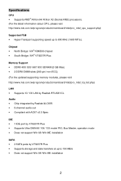
... to 150 MB/s • Does not support Win 98/ Win ME installation 2 Specifications CPU • Supports AMD® Athlon 64/ Athlon X2 (Socket AM2) processors. (For the latest information about CPU, please visit http://www.msi.com.tw/program/products/mainboard/mbd/pro_mbd_cpu_support.php) Supported FSB • Hyper Transport supporting speed up to 800 MHz (1600 MT...
... to 150 MB/s • Does not support Win 98/ Win ME installation 2 Specifications CPU • Supports AMD® Athlon 64/ Athlon X2 (Socket AM2) processors. (For the latest information about CPU, please visit http://www.msi.com.tw/program/products/mainboard/mbd/pro_mbd_cpu_support.php) Supported FSB • Hyper Transport supporting speed up to 800 MHz (1600 MT...
User Guide
Page 10
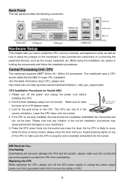
...power and unplug the power cord before installing the CPU. 2. If the CPU is correctly installed, the pins should be completely embedded into the socket. Central Processing Unit: CPU The mainboard supports AMD® Athlon 64 / Athlon X2 processors. MSI Reminds You... Please note that any violation of ...sure to raise the lever up to a 90-degree angle. Gold arrow Correct CPU placeme nt 3. Press the CPU down onto the socket. 4. Replacing the CPU While replacing the CPU, always turn off the ATX power supply or unplug the power supply power cord from the socket. Back Panel...
...power and unplug the power cord before installing the CPU. 2. If the CPU is correctly installed, the pins should be completely embedded into the socket. Central Processing Unit: CPU The mainboard supports AMD® Athlon 64 / Athlon X2 processors. MSI Reminds You... Please note that any violation of ...sure to raise the lever up to a 90-degree angle. Gold arrow Correct CPU placeme nt 3. Press the CPU down onto the socket. 4. Replacing the CPU While replacing the CPU, always turn off the ATX power supply or unplug the power supply power cord from the socket. Back Panel...
User Guide
Page 11
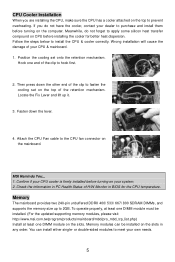
... cooler attached on the top to prevent overheating. Confirm if your CPU cooler is firmly installed before turning on the computer. You can be installed. (For the updated supporting memory modules, please visit http://www.msi.com.tw/program/products/mainboard/mbd/pro_mbd_trp_list.php) Install at least... one end of H/W Monitor in any order. Attach the CPU Fan cable to 2GB. Memory The mainboard provides two...
... cooler attached on the top to prevent overheating. Confirm if your CPU cooler is firmly installed before turning on the computer. You can be installed. (For the updated supporting memory modules, please visit http://www.msi.com.tw/program/products/mainboard/mbd/pro_mbd_trp_list.php) Install at least... one end of H/W Monitor in any order. Attach the CPU Fan cable to 2GB. Memory The mainboard provides two...
User Guide
Page 12
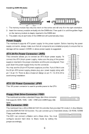
...1.2M, 1.44M and 2.88M floppy disk types. The memory module has only one notch on the center and will be caused. Power Supply The mainboard supports ATX power supply for the power system. You must configure second hard drive to 2 hard disk drives, CD-ROM, 120MB Floppy and other devices. Before inserting... Power Connector: JPW1 This 12V power connector is deeply inserted in until the golden finger on pin 11, 12, 23 & 24 to the CPU. Installing DDRII Modules Volt Notch 1. Insert the memory module vertically into the connector. The plastic clip at each side of the power supply is ...
...1.2M, 1.44M and 2.88M floppy disk types. The memory module has only one notch on the center and will be caused. Power Supply The mainboard supports ATX power supply for the power system. You must configure second hard drive to 2 hard disk drives, CD-ROM, 120MB Floppy and other devices. Before inserting... Power Connector: JPW1 This 12V power connector is deeply inserted in until the golden finger on pin 11, 12, 23 & 24 to the CPU. Installing DDRII Modules Volt Notch 1. Insert the memory module vertically into the connector. The plastic clip at each side of the power supply is ...
User Guide
Page 13
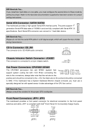
...ATA cable in a 90-degree angle, which will cause the loss of the CPU fan control. R GND L Chassis Intrusion Switch Connector: JCASE1 This connector is for jumper setting instructions. MSI Reminds You... MSI Reminds You... Serial ATA Connector: SATA1/SATA2 The mainboard provides 2 high-speed ...data during transmission. GND 2 CINTRU 1 Fan Power Connectors: CPUFAN1/SFAN1 The CPUFAN1 (processor fan) and SFAN1 (system fan) support system cooling fan with Serial ATA 1.0 specifications. Front Panel Connectors: JFP1/ JFP2 The mainboard provides a front panel connector for the proper...
...ATA cable in a 90-degree angle, which will cause the loss of the CPU fan control. R GND L Chassis Intrusion Switch Connector: JCASE1 This connector is for jumper setting instructions. MSI Reminds You... MSI Reminds You... Serial ATA Connector: SATA1/SATA2 The mainboard provides 2 high-speed ...data during transmission. GND 2 CINTRU 1 Fan Power Connectors: CPUFAN1/SFAN1 The CPUFAN1 (processor fan) and SFAN1 (system fan) support system cooling fan with Serial ATA 1.0 specifications. Front Panel Connectors: JFP1/ JFP2 The mainboard provides a front panel connector for the proper...
User Guide
Page 16
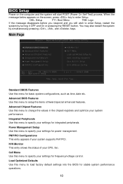
...for stable system performance operations. 10 Integrated Peripherals Use this menu to change the values in the chipset registers and optimize your system supports PnP/PCI. PNP/PCI Configurations This entry appears if your system performance. Load Optimized Defaults Use this menu to specify your settings ...for basic system configurations, such as time, date etc. Advanced BIOS Features Use this menu to specify your CPU, fan. You may also restart the system by turning it OFF and On or pressing the RESET button. BIOS Setup Power on the...
...for stable system performance operations. 10 Integrated Peripherals Use this menu to change the values in the chipset registers and optimize your system supports PnP/PCI. PNP/PCI Configurations This entry appears if your system performance. Load Optimized Defaults Use this menu to specify your settings ...for basic system configurations, such as time, date etc. Advanced BIOS Features Use this menu to specify your CPU, fan. You may also restart the system by turning it OFF and On or pressing the RESET button. BIOS Setup Power on the...


