User Guide
Page 8
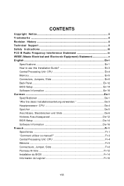
... Statement iv WEEE (Waste Electrical and Electronic Equipment) Statement v English ...En-1 Specifications ...En-1 How to use this Installation Guide En-3 Central Processing Unit: CPU En-4 Memory ...En-5 Connectors, Jumpers, Slots En-6 Back Panel ...En-12 BIOS Setup ...En-14 Software Information En-16 G e rm an ...De-1 Spezifikationen De-1 "W ie Sie diese...
... Statement iv WEEE (Waste Electrical and Electronic Equipment) Statement v English ...En-1 Specifications ...En-1 How to use this Installation Guide En-3 Central Processing Unit: CPU En-4 Memory ...En-5 Connectors, Jumpers, Slots En-6 Back Panel ...En-12 BIOS Setup ...En-14 Software Information En-16 G e rm an ...De-1 Spezifikationen De-1 "W ie Sie diese...
User Guide
Page 9
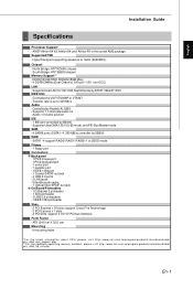
...Specifications Processor Support* - AMD® Athlon 64 X2, Athlon 64 and Athlon FX in the socket AM2 package. South Bridge: ATI® SB600 chipset Memory Support** - Supported FSB - Supports 7.1 channels audio out - SATA1~4 support RAID0/ RAID1/ RAID0+1 or JBOD mode Floppy - 1 floppy port Connectors Back... Bridge: ATI® RD580 chipset - Supports Dual LAN 10/100/1000 Fast Ethernet by Realtek ALC883 - Controlled by RTL8111B & 8110SC IEEE 1394 - ATX (24.5 cm X 30.5 cm) Mounting - 9 mounting holes *For the latest information about CPU, please visit http:// www.ms i.com. php...
...Specifications Processor Support* - AMD® Athlon 64 X2, Athlon 64 and Athlon FX in the socket AM2 package. South Bridge: ATI® SB600 chipset Memory Support** - Supported FSB - Supports 7.1 channels audio out - SATA1~4 support RAID0/ RAID1/ RAID0+1 or JBOD mode Floppy - 1 floppy port Connectors Back... Bridge: ATI® RD580 chipset - Supports Dual LAN 10/100/1000 Fast Ethernet by Realtek ALC883 - Controlled by RTL8111B & 8110SC IEEE 1394 - ATX (24.5 cm X 30.5 cm) Mounting - 9 mounting holes *For the latest information about CPU, please visit http:// www.ms i.com. php...
User Guide
Page 13
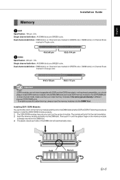
...at each side of the DIMM slot will only fit in different channel DDR DIMM slots. - DIMM slot(s) on the memory module is not backward compatible, you install memory modules of module. Single channel definition : All DIMM slots are not interchangeable with DDR and the DDRII standard is deeply ... color. 64x2=128 pin 56x2=112 pin Important -DDRII modules are GREEN color. Installing DDR/ DDRII Modules You can find the notch on the memory modules and the volt on Channel B are GREEN color. The module will automatically close. Then push it in until the golden finger on Channel ...
...at each side of the DIMM slot will only fit in different channel DDR DIMM slots. - DIMM slot(s) on the memory module is not backward compatible, you install memory modules of module. Single channel definition : All DIMM slots are not interchangeable with DDR and the DDRII standard is deeply ... color. 64x2=128 pin 56x2=112 pin Important -DDRII modules are GREEN color. Installing DDR/ DDRII Modules You can find the notch on the memory modules and the volt on Channel B are GREEN color. The module will automatically close. Then push it in until the golden finger on Channel ...
User Guide
Page 17
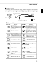
...on This will initialize Floppy Drive and 3 4 message to the USB pinheader in - 3 stalled properly. Memory Detection Test Testing Base and Extended Memory 1 2 Testing onboard memory size. D-Bracket™ 2 is a external USB Bracket that fail the system, such as VGA, RAM... Description LEDs signal Description System Power ON The D-LED will start showing information 3 4 about logo, processor brand name, etc... The 1 2 Testing base memory from 240K to all problems that support both USB1.1 & 2.0 spec. properly. 1 2 Decompressing BIOS image to RAM 1 2 Assign Resources to 3 D-...
...on This will initialize Floppy Drive and 3 4 message to the USB pinheader in - 3 stalled properly. Memory Detection Test Testing Base and Extended Memory 1 2 Testing onboard memory size. D-Bracket™ 2 is a external USB Bracket that fail the system, such as VGA, RAM... Description LEDs signal Description System Power ON The D-LED will start showing information 3 4 about logo, processor brand name, etc... The 1 2 Testing base memory from 240K to all problems that support both USB1.1 & 2.0 spec. properly. 1 2 Decompressing BIOS image to RAM 1 2 Assign Resources to 3 D-...
User Guide
Page 19
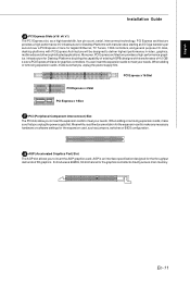
... removing expansion cards, make sure that you unplug the power supply first. AGP is an interface specification designed for the graphics controller to directlyaccess main memory. Meanwhile, readthe documentation forthe expansion cardto makeany necessary hardware or software settings for Desktop Platforms with PCI Express Architecture will be designed to meet your...
... removing expansion cards, make sure that you unplug the power supply first. AGP is an interface specification designed for the graphics controller to directlyaccess main memory. Meanwhile, readthe documentation forthe expansion cardto makeany necessary hardware or software settings for Desktop Platforms with PCI Express Architecture will be designed to meet your...
User Guide
Page 22
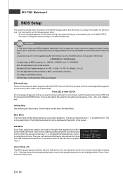
... under continuous update for optimum use control keys ( ↑↓ ) to highlight the field and press to call up , the 1st line appearing after the memory count is displayed at the bottom of certain fields that means a sub-menu containing additional options can use and the possible selections for the highlighted...
... under continuous update for optimum use control keys ( ↑↓ ) to highlight the field and press to call up , the 1st line appearing after the memory count is displayed at the bottom of certain fields that means a sub-menu containing additional options can use and the possible selections for the highlighted...


