

User Guide
Page 4
... equipment in an environment unconditioned, storage temperature above 600 C (1400F), it up. 5. Make sure the voltage of the power source and adjust properly 110/220V be obtained from the user's manual, please contact your place of the following help resources for further guidance. † Visit the MSI homepage & FAQ site for technical guide, BIOS updates, driver updates, and other information: http://www...
... equipment in an environment unconditioned, storage temperature above 600 C (1400F), it up. 5. Make sure the voltage of the power source and adjust properly 110/220V be obtained from the user's manual, please contact your place of the following help resources for further guidance. † Visit the MSI homepage & FAQ site for technical guide, BIOS updates, driver updates, and other information: http://www...
User Guide
Page 8
... CPU Cooler Set 2-5 Memory ...2-7 DIMM Module Combination 2-7 Installing DDR Modules 2-8 Power Supply ...2-9 ATX 24-Pin Power Connector: ATX1 2-9 ATX 12V Power Connector: JPW 1 2-9 Back Panel ...2-10 Mouse/Keyboard Connector 2-10 VGA Connector ( for GeForce 6150 only 2-10 Digital Panel Connector (for GeForce 6150 only)(optional 2-11 USB Connectors 2-11 LAN (RJ-45) Jack:10/100 LAN (RTL8201CL) or Giga-bit LAN (VSC8201RX : optional 2-12 Audio Port Connectors & Audio Header (J1 2-13 IEEE 1394 Port (optional 2-13 Parallel Port Connector: LPT1 2-14 Connectors ...2-15 Floppy Disk Drive...
... CPU Cooler Set 2-5 Memory ...2-7 DIMM Module Combination 2-7 Installing DDR Modules 2-8 Power Supply ...2-9 ATX 24-Pin Power Connector: ATX1 2-9 ATX 12V Power Connector: JPW 1 2-9 Back Panel ...2-10 Mouse/Keyboard Connector 2-10 VGA Connector ( for GeForce 6150 only 2-10 Digital Panel Connector (for GeForce 6150 only)(optional 2-11 USB Connectors 2-11 LAN (RJ-45) Jack:10/100 LAN (RTL8201CL) or Giga-bit LAN (VSC8201RX : optional 2-12 Audio Port Connectors & Audio Header (J1 2-13 IEEE 1394 Port (optional 2-13 Parallel Port Connector: LPT1 2-14 Connectors ...2-15 Floppy Disk Drive...

User Guide
Page 9
... USB Connectors: JUSB1/ JUSB2 2-23 Button ...2-23 Clear CMOS Button: SW1 2-24 Slots ...2-25 PCI Express Slots 2-25 PCI (Peripheral Component Interconnect) Slots 2-25 PCI Interrupt Request Routing 2-25 Chapter 3. BIOS Setup 3-1 Entering Setup ...3-2 Control Keys 3-2 Getting Help 3-3 The Main Menu ...3-4 Standard CMOS Features 3-6 Advanced BIOS Features 3-9 Advanced Chipset Features 3-11 Integrated Peripherals 3-14 Power Management Features 3-17 PNP/PCI Configurations 3-20 H/W Monitor ...3-23 Cell_Menu ...3-24 Load Fail-Safe/ Optimized Defaults 3-26 BIOS Setting Password 3-27...
... USB Connectors: JUSB1/ JUSB2 2-23 Button ...2-23 Clear CMOS Button: SW1 2-24 Slots ...2-25 PCI Express Slots 2-25 PCI (Peripheral Component Interconnect) Slots 2-25 PCI Interrupt Request Routing 2-25 Chapter 3. BIOS Setup 3-1 Entering Setup ...3-2 Control Keys 3-2 Getting Help 3-3 The Main Menu ...3-4 Standard CMOS Features 3-6 Advanced BIOS Features 3-9 Advanced Chipset Features 3-11 Integrated Peripherals 3-14 Power Management Features 3-17 PNP/PCI Configurations 3-20 H/W Monitor ...3-23 Cell_Menu ...3-24 Load Fail-Safe/ Optimized Defaults 3-26 BIOS Setting Password 3-27...

User Guide
Page 10
... Point Mode 4-7 WLAN Card Mode 4-8 Live Update ...4-9 MEGA STICK ...4-10 Basic Function 4-10 Non-Unicode programs supported 4-12 PC Alert ...4-14 Power on Agent 4-15 Power Off / Restart 4-16 Start W ith ...4-16 Auto Login 4-17 Chapter 5. nVidia RAID Introduction 5-1 Introduction ...5-2 System Requirement 5-2 RAID Arrays 5-2 Summary of RAID Configurations 5-2 RAID Configuration 5-3 Basic Configuration Instructions 5-3 Setting Up the NVRAID BIOS 5-3 Installing the RAID Driver (for bootable RAID Array 5-7 NVIDIA RAID Utility Installation 5-9 Installing the NVIDIA RAID Software...
... Point Mode 4-7 WLAN Card Mode 4-8 Live Update ...4-9 MEGA STICK ...4-10 Basic Function 4-10 Non-Unicode programs supported 4-12 PC Alert ...4-14 Power on Agent 4-15 Power Off / Restart 4-16 Start W ith ...4-16 Auto Login 4-17 Chapter 5. nVidia RAID Introduction 5-1 Introduction ...5-2 System Requirement 5-2 RAID Arrays 5-2 Summary of RAID Configurations 5-2 RAID Configuration 5-3 Basic Configuration Instructions 5-3 Setting Up the NVRAID BIOS 5-3 Installing the RAID Driver (for bootable RAID Array 5-7 NVIDIA RAID Utility Installation 5-9 Installing the NVIDIA RAID Software...

User Guide
Page 13
... PCI Express x 1 slot. † Two 32-bit Master 3.3v/5v PCI Bus slots. Onboard Serial ATA † Supports 4 SATAII ports with PIO, Bus Master and Ultra DMA 66/100/133 operation modes. † Can connect up to 8 ports. - USB Interface † 8 USB ports - 4 ports in the rear I/O, 4 ports via the external bracket 1-2 Supports one PCI-E x16 slot. - ACPI & PC2001 compliant enhanced power management. - nForce 430 supports dual channel native SATA controller up to 300MB/s, nForce 410 supports single channel native SATA controller up to 4 IDE devices. Onboard IDE...
... PCI Express x 1 slot. † Two 32-bit Master 3.3v/5v PCI Bus slots. Onboard Serial ATA † Supports 4 SATAII ports with PIO, Bus Master and Ultra DMA 66/100/133 operation modes. † Can connect up to 8 ports. - USB Interface † 8 USB ports - 4 ports in the rear I/O, 4 ports via the external bracket 1-2 Supports one PCI-E x16 slot. - ACPI & PC2001 compliant enhanced power management. - nForce 430 supports dual channel native SATA controller up to 300MB/s, nForce 410 supports single channel native SATA controller up to 4 IDE devices. Onboard IDE...

User Guide
Page 14
... is required. On-Board Peripherals † On-Board Peripherals include: - 1 floppy port supports 2 FDD with PCI v2.2. - Audio † 8 channels HD audio codec Realtek ALC880 - To create a bootable RAID volume for GeForce 6150, optional) - 1 RJ-45 LAN Jack - 2 IDE ports support 4 IDE devices - 2/4 serial ATAII ports (nForce 410/430) BIOS † The mainboard BIOS provides "Plug & Play" BIOS which detects the peripheral devices and expansion cards of the board automatically. 1-3 Please note that users cannot install OS, either WinME...
... is required. On-Board Peripherals † On-Board Peripherals include: - 1 floppy port supports 2 FDD with PCI v2.2. - Audio † 8 channels HD audio codec Realtek ALC880 - To create a bootable RAID volume for GeForce 6150, optional) - 1 RJ-45 LAN Jack - 2 IDE ports support 4 IDE devices - 2/4 serial ATAII ports (nForce 410/430) BIOS † The mainboard BIOS provides "Plug & Play" BIOS which detects the peripheral devices and expansion cards of the board automatically. 1-3 Please note that users cannot install OS, either WinME...
User Guide
Page 24
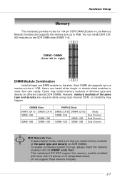
... into the DIMM1 slots first. - GREEN Slots PURPLE Slots DIMM1 (CH A) 128MB~1GB 128MB~1GB DIMM3 (CH A) 128MB~1GB 128MB~1GB DIMM2 (CH B) DIMM4 (CH B) 128MB~1GB 128MB~1GB 128MB~1GB 128MB~1GB Mode Dual Channel Dual Channel Dual Channel MSI Reminds You... - Hardware Setup Memory The mainboard provides 4 slots for 184-pin DDR DIMM (Double In-Line Memory Module) modules and supports the memory size up to meet their...
... into the DIMM1 slots first. - GREEN Slots PURPLE Slots DIMM1 (CH A) 128MB~1GB 128MB~1GB DIMM3 (CH A) 128MB~1GB 128MB~1GB DIMM2 (CH B) DIMM4 (CH B) 128MB~1GB 128MB~1GB 128MB~1GB 128MB~1GB Mode Dual Channel Dual Channel Dual Channel MSI Reminds You... - Hardware Setup Memory The mainboard provides 4 slots for 184-pin DDR DIMM (Double In-Line Memory Module) modules and supports the memory size up to meet their...

User Guide
Page 27
... connection VGA Connector The mainboard provides a DB 15-pin female connector to connect a VGA monitor. 5 1 15 11 VGA Connector (DB 15-pin) Pin Signal Description Pin Signal Description 1 RED 2 GREEN 3 BLUE 4 N/C 5 GND 6 GND 7 GND 8 GND 9 +5V 10 GND 11 N/C 12 SDA 13 Horizontal Sync 14 Vertical Sync 15 SCL 2-10 MS-7207 M-ATX Mainboard Mouse Back Panel Parallel 1394 Port L-In LAN (Optional) Keyboard DVI Port (for GeForce 6150) (optional) VGA Port USB Ports USB L-Out Ports Mic Mouse/Keyboard Connector...
... connection VGA Connector The mainboard provides a DB 15-pin female connector to connect a VGA monitor. 5 1 15 11 VGA Connector (DB 15-pin) Pin Signal Description Pin Signal Description 1 RED 2 GREEN 3 BLUE 4 N/C 5 GND 6 GND 7 GND 8 GND 9 +5V 10 GND 11 N/C 12 SDA 13 Horizontal Sync 14 Vertical Sync 15 SCL 2-10 MS-7207 M-ATX Mainboard Mouse Back Panel Parallel 1394 Port L-In LAN (Optional) Keyboard DVI Port (for GeForce 6150) (optional) VGA Port USB Ports USB L-Out Ports Mic Mouse/Keyboard Connector...
User Guide
Page 28
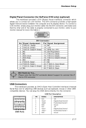
... T.M.D.S. The DVI connector provides a high-speed digital interconnection between the computer and its display device. To connect a LCD monitor, simply plug your monitor manual for GeForce 6150 only) (optional) The mainboard provides a DVI (Digital Visual Interface) connector which allows you to your monitor cable into the connector. Please note that the other USBcompatible devices. Sub to connect the D- Data110 T.M.D.S. MSI Reminds You... Data018 T.M.D.S. Clock+ 24 T.M.D.S. USB Port Description 1 23 4 5 67 8 USB Ports PIN SIGNAL 1 VCC...
... T.M.D.S. The DVI connector provides a high-speed digital interconnection between the computer and its display device. To connect a LCD monitor, simply plug your monitor manual for GeForce 6150 only) (optional) The mainboard provides a DVI (Digital Visual Interface) connector which allows you to your monitor cable into the connector. Please note that the other USBcompatible devices. Sub to connect the D- Data110 T.M.D.S. MSI Reminds You... Data018 T.M.D.S. Clock+ 24 T.M.D.S. USB Port Description 1 23 4 5 67 8 USB Ports PIN SIGNAL 1 VCC...
User Guide
Page 42
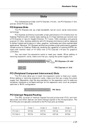
... power supply first. PCI Express x16 slot PCI Express x1 slot PCI (Peripheral Component Interconnect) Slots The PCI slots allow you unplug the power supply first. The PCI IRQ pins are hardware lines over a PCI Express x1 lane for the expansion card, such as jumpers, switches or BIOS configuration. Meanwhile, read the documentation for the expansion card to make any necessary hardware or software settings for Gigabit Ethernet, TV Tuners, 1394 controllers, and general purpose I /O infrastructure for Desktop...
... power supply first. PCI Express x16 slot PCI Express x1 slot PCI (Peripheral Component Interconnect) Slots The PCI slots allow you unplug the power supply first. The PCI IRQ pins are hardware lines over a PCI Express x1 lane for the expansion card, such as jumpers, switches or BIOS configuration. Meanwhile, read the documentation for the expansion card to make any necessary hardware or software settings for Gigabit Ethernet, TV Tuners, 1394 controllers, and general purpose I /O infrastructure for Desktop...
User Guide
Page 49
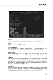
... defines the HDD parameters. In Auto mode, the system automatically determines the best mode for the IDE devices that the onboard IDE interface supports. Block Mode W hen the setting is Auto, it will read or write more sector at every circle to enable or disable the DMA (Direct Memory Access) mode. Modes 0 through 4 provide successively increased performance. Setting options: [Auto], [SWDMA0], [SWDMA1], [SWDMA2], [MWDMA0], [MWDMA1], [MW DMA2], [UDMA0], [UDMA1], [UDMA2], [UDMA3...
... defines the HDD parameters. In Auto mode, the system automatically determines the best mode for the IDE devices that the onboard IDE interface supports. Block Mode W hen the setting is Auto, it will read or write more sector at every circle to enable or disable the DMA (Direct Memory Access) mode. Modes 0 through 4 provide successively increased performance. Setting options: [Auto], [SWDMA0], [SWDMA1], [SWDMA2], [MWDMA0], [MWDMA1], [MW DMA2], [UDMA0], [UDMA1], [UDMA2], [UDMA3...

User Guide
Page 53
... selectable. Setting options:[Auto], [Limit]. Please note that memory is 3-11 MCT Timing Mode This field has the capacity to [Manual], the following 4 fields default value.. The settings are: [Auto], [Manual]. User Config mode This field has the capacity to set this frequency. If you to automatically detect all of Burst-Length for DRAM. Memclock Mode Users can place an artificial memory clock on the system. BIOS Setup Advanced Chipset Features MSI Reminds You...
... selectable. Setting options:[Auto], [Limit]. Please note that memory is 3-11 MCT Timing Mode This field has the capacity to [Manual], the following 4 fields default value.. The settings are: [Auto], [Manual]. User Config mode This field has the capacity to set this frequency. If you to automatically detect all of Burst-Length for DRAM. Memclock Mode Users can place an artificial memory clock on the system. BIOS Setup Advanced Chipset Features MSI Reminds You...
User Guide
Page 54
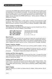
... the memory space below 16MB. RGB/TV Display This item allows you to update the BIOS with a Flash utility. Setting options are used to South Bridge. Setting options: [Disbale Onchip VGA if have PCIe VGA], [Both exist and OnChip VGA by unauthorized users or computer viruses. Larger frame buffer size increases video performance. W hen this Flash Protection function. Hyper Transport Configuration The following items are : [PCI Express] The system initializes the installed PCI Express card first. Setting options: [Auto...
... the memory space below 16MB. RGB/TV Display This item allows you to update the BIOS with a Flash utility. Setting options are used to South Bridge. Setting options: [Disbale Onchip VGA if have PCIe VGA], [Both exist and OnChip VGA by unauthorized users or computer viruses. Larger frame buffer size increases video performance. W hen this Flash Protection function. Hyper Transport Configuration The following items are : [PCI Express] The system initializes the installed PCI Express card first. Setting options: [Auto...

User Guide
Page 57
...controller. Setting options: [Enabled], [Disabled]. Setting options: [Pin Setup], [MII], [RGMII]. If you install add-on the system board and you wish to use it. BIOS Setup Onboard IEEE1394 Controller This setting allows you to specify the operation mode for Serial Port 1. AZALIA AUDIO Select Enabled to enter the sub-menu and the following screen appears: Onboard Floppy Controller Select [Enabled] if your system. Setting options: [Disabled], [IrDA], [ASKIR]. [Disabled] Disable RS-232C Serial Port [IrDA] IrDA-compliant Serial Infrared Port [ASK IR] Amplitude Shift Keyed...
...controller. Setting options: [Enabled], [Disabled]. Setting options: [Pin Setup], [MII], [RGMII]. If you install add-on the system board and you wish to use it. BIOS Setup Onboard IEEE1394 Controller This setting allows you to specify the operation mode for Serial Port 1. AZALIA AUDIO Select Enabled to enter the sub-menu and the following screen appears: Onboard Floppy Controller Select [Enabled] if your system. Setting options: [Disabled], [IrDA], [ASKIR]. [Disabled] Disable RS-232C Serial Port [IrDA] IrDA-compliant Serial Infrared Port [ASK IR] Amplitude Shift Keyed...

User Guide
Page 58
... an IDE interface with support for two IDE channels. Choose [Both] to enable or disabled the nVidia RAID function. nVidia RAID Setup Press to enter the sub-menu and the following screen appears. Settings options: [Enabled], [Disabled]. Serial-ATA 1/2 This field allows you to enable/ disable the PCI IDE busmaster. Setting options: [Disabled], [Primary], [Secondary], [Both]. SATA Devices Configuration Press to enable or disabled the SATA controllers. Setting options: [Disabled], [Enabled]. MS-7207 M-ATX Mainboard IDE Devices Configuration Press to enter the sub-menu and...
... an IDE interface with support for two IDE channels. Choose [Both] to enable or disabled the nVidia RAID function. nVidia RAID Setup Press to enter the sub-menu and the following screen appears. Settings options: [Enabled], [Disabled]. Serial-ATA 1/2 This field allows you to enable/ disable the PCI IDE busmaster. Setting options: [Disabled], [Primary], [Secondary], [Both]. SATA Devices Configuration Press to enable or disabled the SATA controllers. Setting options: [Disabled], [Enabled]. MS-7207 M-ATX Mainboard IDE Devices Configuration Press to enter the sub-menu and...
User Guide
Page 62
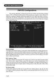
...], [224], [248]. Setting options: [4], [5], [7], [10], [11], [Auto]. MS-7207 M-ATX Mainboard PNP/PCI Configurations This section describes configuring the PCI bus system and PnP (Plug & Play) feature. Selecting [Auto] allows BIOS to operate at speeds nearing the speed the CPU itself uses when communicating with its special components. PCI, or Peripheral Component Interconnect, is strongly recommended that only experienced users should set to [Yes], the system will reset ESCD NVRAM right...
...], [224], [248]. Setting options: [4], [5], [7], [10], [11], [Auto]. MS-7207 M-ATX Mainboard PNP/PCI Configurations This section describes configuring the PCI bus system and PnP (Plug & Play) feature. Selecting [Auto] allows BIOS to operate at speeds nearing the speed the CPU itself uses when communicating with its special components. PCI, or Peripheral Component Interconnect, is strongly recommended that only experienced users should set to [Yes], the system will reset ESCD NVRAM right...
User Guide
Page 65
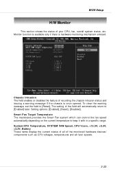
... the current temperature to [Enabled] later. Chassis Intrusion The field enables or disables the feature of the field will automatically return to keep it with in a specific range. System/CPU Temperature, SYSTEM FAN Speed, CPU Vcore, +12.0V, +5.0V, +3.3V, Battery These items display the current status of all of your CPU, fan, overall system status, etc. To clear the warning message, set the field to [Reset]. BIOS Setup H/W Monitor This...
... the current temperature to [Enabled] later. Chassis Intrusion The field enables or disables the feature of the field will automatically return to keep it with in a specific range. System/CPU Temperature, SYSTEM FAN Speed, CPU Vcore, +12.0V, +5.0V, +3.3V, Battery These items display the current status of all of your CPU, fan, overall system status, etc. To clear the warning message, set the field to [Reset]. BIOS Setup H/W Monitor This...
User Guide
Page 89
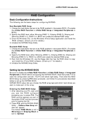
... part of Integrated Peripherals in BIOS before configuring the NVRAID BIOS. The default RAID M ode is set to Mirroring and Striping Block is set to set up the NVRAID BIOS. nVIDIA RAID Introduction RAID Configuration Basic Configuration Instructions The following are to be RAID enabled in the system BIOS. (To enable the nVidia RAID Function in nVidia RAID Setup of Integrated Peripherals in BIOS.) 2. Boot from the W indows CD, use the floppy disk that are to be RAID enabled...
... part of Integrated Peripherals in BIOS before configuring the NVRAID BIOS. The default RAID M ode is set to Mirroring and Striping Block is set to set up the NVRAID BIOS. nVIDIA RAID Introduction RAID Configuration Basic Configuration Instructions The following are to be RAID enabled in the system BIOS. (To enable the nVidia RAID Function in nVidia RAID Setup of Integrated Peripherals in BIOS.) 2. Boot from the W indows CD, use the floppy disk that are to be RAID enabled...
User Guide
Page 93
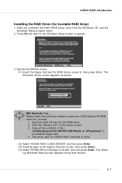
... nVIDIA Serial ATA RAID driver for yourself. 1. After you complete the RAID BIOS setup, boot from the W indows CD, and the W indows Setup program starts. 2. Copy all the contents in the : \\nVidia\System\C51+MCP51\IDE\Win2k or XP\sataraid\ to a formatted floppy disk. 4. nVIDIA RAID Introduction Installing the RAID Driver (for nVIDIA RAID controller is done. (2) Select "NVIDIA RAID CLASS DRIVER" and then press Enter. (3) Press S again at the Specify Devices screen...
... nVIDIA Serial ATA RAID driver for yourself. 1. After you complete the RAID BIOS setup, boot from the W indows CD, and the W indows Setup program starts. 2. Copy all the contents in the : \\nVidia\System\C51+MCP51\IDE\Win2k or XP\sataraid\ to a formatted floppy disk. 4. nVIDIA RAID Introduction Installing the RAID Driver (for nVIDIA RAID controller is done. (2) Select "NVIDIA RAID CLASS DRIVER" and then press Enter. (3) Press S again at the Specify Devices screen...

User Guide
Page 114
.... Installation for Windows 2000/XP For W indows® 2000, you can get access to 2-, 4-, 6- The setup screen will automatically appear. 2. Click Realtek HD Audio Driver. Insert the companion CD into the CD-ROM drive. MS-7207 M-ATX Mainboard Installing the Audio Driver You need to install the driver for Realtek ALC880 codec to function properly before you must install W indows® XP Service Pack1 or later before installing the driver.
.... Installation for Windows 2000/XP For W indows® 2000, you can get access to 2-, 4-, 6- The setup screen will automatically appear. 2. Click Realtek HD Audio Driver. Insert the companion CD into the CD-ROM drive. MS-7207 M-ATX Mainboard Installing the Audio Driver You need to install the driver for Realtek ALC880 codec to function properly before you must install W indows® XP Service Pack1 or later before installing the driver.


