User Guide
Page 2
... Date August 2006 Technical Support If a problem arises with your place of Microsoft Corporation. Alternatively, please try the following help resources for FAQ, technical guide, BIOS updates, driver updates, and other countries. ...Technologies Ltd. Award® is a registered trademark of NVIDIA Corporation in the United States and/or other information: http://www.msi.com.tw/program/service/faq/ faq/esc_faq_list.php Contact our technical staff at: http://support.msi.com.tw ii Copyright Notice The material in this document, but no solution can be obtained from the user's manual...
... Date August 2006 Technical Support If a problem arises with your place of Microsoft Corporation. Alternatively, please try the following help resources for FAQ, technical guide, BIOS updates, driver updates, and other countries. ...Technologies Ltd. Award® is a registered trademark of NVIDIA Corporation in the United States and/or other information: http://www.msi.com.tw/program/service/faq/ faq/esc_faq_list.php Contact our technical staff at: http://support.msi.com.tw ii Copyright Notice The material in this document, but no solution can be obtained from the user's manual...
User Guide
Page 8
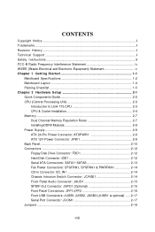
... Started 1-1 Mainboard Specifications 1-2 Mainboard Layout 1-4 Packing Checklist 1-5 Chapter 2 Hardware Setup 2-1 Quick Components Guide 2-2 CPU (Central Processing Unit 2-3 Introduction to LGA 775 CPU 2-3 CPU & Cooler Installation 2-4 Memory ...2-7 Dual Channel Memory Population Rules 2-7 Installing DDRII Modules 2-8 Power Supply ...2-9 ATX 24-Pin Power Connector: ATXPWR1 2-9 ATX 12V Power Connector: JPW 1 2-9 Back Panel ...2-10 Connectors ...2-12 Floppy Disk Drive Connector: FDD1 2-12 Hard Disk Connector: IDE1 2-12 Serial ATA Connectors: SATA1~SATA6 2-13 Fan Power Connectors...
... Started 1-1 Mainboard Specifications 1-2 Mainboard Layout 1-4 Packing Checklist 1-5 Chapter 2 Hardware Setup 2-1 Quick Components Guide 2-2 CPU (Central Processing Unit 2-3 Introduction to LGA 775 CPU 2-3 CPU & Cooler Installation 2-4 Memory ...2-7 Dual Channel Memory Population Rules 2-7 Installing DDRII Modules 2-8 Power Supply ...2-9 ATX 24-Pin Power Connector: ATXPWR1 2-9 ATX 12V Power Connector: JPW 1 2-9 Back Panel ...2-10 Connectors ...2-12 Floppy Disk Drive Connector: FDD1 2-12 Hard Disk Connector: IDE1 2-12 Serial ATA Connectors: SATA1~SATA6 2-13 Fan Power Connectors...
User Guide
Page 9
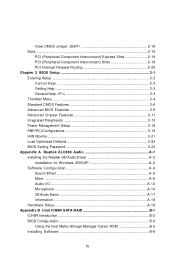
Clear CMOS Jumper: JBAT1 2-18 Slots ...2-19 PCI (Peripheral Component Interconnect) Express Slots 2-19 PCI (Peripheral Component Interconnect) Slots 2-19 PCI Interrupt Request Routing 2-20 Chapter 3 BIOS Setup 3-1 Entering Setup ...3-2 Control Keys 3-3 Getting Help 3-3 General Help
Clear CMOS Jumper: JBAT1 2-18 Slots ...2-19 PCI (Peripheral Component Interconnect) Express Slots 2-19 PCI (Peripheral Component Interconnect) Slots 2-19 PCI Interrupt Request Routing 2-20 Chapter 3 BIOS Setup 3-1 Entering Setup ...3-2 Control Keys 3-3 Getting Help 3-3 General Help
User Guide
Page 12
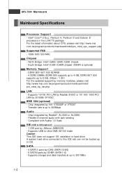
... 4 GB, DDRII 667/ 533 supports up to 8 GB, 240pin / 1.8V) For the updated supporting memory modules, please visit ht t p: / / w w w. A system hard drive connected to this IDE slot can not be booted up to OS. North Bridge: Intel® G965/ Q965/ Q963 chipset - c om . Flexible 8-channel audio with Azalia 1.0 Spec IDE (USB to 300 MB/s 1-2 Supports USB to 400Mbps Audio - SATA - 4 SATA II ports by ICH8 (SATA1/3/5/6) - 6 SATAII ports by Realtek® ALC883 or...
... 4 GB, DDRII 667/ 533 supports up to 8 GB, 240pin / 1.8V) For the updated supporting memory modules, please visit ht t p: / / w w w. A system hard drive connected to this IDE slot can not be booted up to OS. North Bridge: Intel® G965/ Q965/ Q963 chipset - c om . Flexible 8-channel audio with Azalia 1.0 Spec IDE (USB to 300 MB/s 1-2 Supports USB to 400Mbps Audio - SATA - 4 SATA II ports by ICH8 (SATA1/3/5/6) - 6 SATAII ports by Realtek® ALC883 or...

User Guide
Page 13
...Parallel port supporting SPP/EPP/ECP mode - 1 VGA Port - 1 IEEE 1394 port (optional) - 4 USB 2.0 Ports. - 1 LAN jack - 6 flexible audio jacks On-Board Pinheaders - 1 COM port pinheader - 3 USB 2.0 pinheaders (JUSB1 is optional) - 1 CD-IN pinheader - 1 SPDIF-out pinheader (optional) Slots - 1 PCI Express x16 slot (for ICH8R only) - Form Factor - Micro-ATX (24.4cm X 24.4cm) Mounting - 8 mounting holes 1-3 SATA1~6 support RAID 0/ 1/ 0+1 or RAID 5 mode by ICH8R Floppy - 1 floppy port - Getting Started RAID(for G965M/ Q965M series) - 1 PCI Express x1 slot - 2 PCI slots, support 3.3V/ 5V PCI bus...
...Parallel port supporting SPP/EPP/ECP mode - 1 VGA Port - 1 IEEE 1394 port (optional) - 4 USB 2.0 Ports. - 1 LAN jack - 6 flexible audio jacks On-Board Pinheaders - 1 COM port pinheader - 3 USB 2.0 pinheaders (JUSB1 is optional) - 1 CD-IN pinheader - 1 SPDIF-out pinheader (optional) Slots - 1 PCI Express x16 slot (for ICH8R only) - Form Factor - Micro-ATX (24.4cm X 24.4cm) Mounting - 8 mounting holes 1-3 SATA1~6 support RAID 0/ 1/ 0+1 or RAID 5 mode by ICH8R Floppy - 1 floppy port - Getting Started RAID(for G965M/ Q965M series) - 1 PCI Express x1 slot - 2 PCI slots, support 3.3V/ 5V PCI bus...

User Guide
Page 24
... used to provide power to the CPU. You may use the 20-pin ATX power supply, please plug your power supply along with pin 1 & pin 13 (refer to the image at the right hand). JPW1 2 1 4 3 Pin Definition PIN SIGNAL 1 GND 2 GND 3 12V 4 12V pin 13 pin 12 Important 1. Maker sure that all the connectors are aligned. Power supply of the mainboard. 2. Hardware Setup Power Supply ATX 24-Pin Power Connector: ATXPWR1 This connector allows you like to use the 20-pin ATX power supply...
... used to provide power to the CPU. You may use the 20-pin ATX power supply, please plug your power supply along with pin 1 & pin 13 (refer to the image at the right hand). JPW1 2 1 4 3 Pin Definition PIN SIGNAL 1 GND 2 GND 3 12V 4 12V pin 13 pin 12 Important 1. Maker sure that all the connectors are aligned. Power supply of the mainboard. 2. Hardware Setup Power Supply ATX 24-Pin Power Connector: ATXPWR1 This connector allows you like to use the 20-pin ATX power supply...
User Guide
Page 27
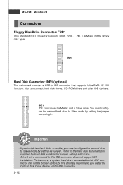
... instruction. - Furthermore, a system hard drive connected to this IDE connector. 2-12 A hard drive connected to this IDE connector can connect a Master and a Slave drive. IDE1 IDE can not be booted up to this IDE connector does not support OS installation. Important - Refer to IDE connector that supports Ultra DMA 66/ 100 function. FDD1 Hard Disk Connector: IDE1 (optional) The mainboard provides a USB to the hard disk documentation supplied by setting its jumper. You can connect hard disk drives, CD-ROM drives and other IDE devices. If you install two hard disks on cable...
... instruction. - Furthermore, a system hard drive connected to this IDE connector. 2-12 A hard drive connected to this IDE connector can connect a Master and a Slave drive. IDE1 IDE can not be booted up to this IDE connector does not support OS installation. Important - Refer to IDE connector that supports Ultra DMA 66/ 100 function. FDD1 Hard Disk Connector: IDE1 (optional) The mainboard provides a USB to the hard disk documentation supplied by setting its jumper. You can connect hard disk drives, CD-ROM drives and other IDE devices. If you install two hard disks on cable...

User Guide
Page 33
... clear CMOS by shorting 2-3 pin while the system is off. Then return to keep the data of system configuration. If you want to clear the system configuration, set the JBAT1 (Clear CMOS Jumper ) to clear data. 1 JBAT1 1 3 Keep Data 1 3 Clear Data Important You can automatically boot OS every time it will damage the mainboard. 2-18 it is turned on ; MS-7241 Mainboard Jumpers Clear CMOS Jumper: JBAT1 There is a CMOS RAM onboard that has a power supply...
... clear CMOS by shorting 2-3 pin while the system is off. Then return to keep the data of system configuration. If you want to clear the system configuration, set the JBAT1 (Clear CMOS Jumper ) to clear data. 1 JBAT1 1 3 Keep Data 1 3 Clear Data Important You can automatically boot OS every time it will damage the mainboard. 2-18 it is turned on ; MS-7241 Mainboard Jumpers Clear CMOS Jumper: JBAT1 There is a CMOS RAM onboard that has a power supply...

User Guide
Page 34
... PCI Express Architecture will be designed to configure any necessary hardware or software settings for Gigabit Ethernet, TV Tuners, 1394 controllers, and general purpose I /O infrastructure for Desktop Platforms with transfer rates starting at 2.5 Giga transfers per second over a PCI Express x16 lane for graphics controllers, while PCI Express x1 supports transfer rate of 133 MBps. 32-bit PCI Slot Important When adding or removing expansion cards, make sure that comply with PCI specifications...
... PCI Express Architecture will be designed to configure any necessary hardware or software settings for Gigabit Ethernet, TV Tuners, 1394 controllers, and general purpose I /O infrastructure for Desktop Platforms with transfer rates starting at 2.5 Giga transfers per second over a PCI Express x16 lane for graphics controllers, while PCI Express x1 supports transfer rate of 133 MBps. 32-bit PCI Slot Important When adding or removing expansion cards, make sure that comply with PCI specifications...

User Guide
Page 42
... LBA mode disabled. Setting to enable or disable the LBA Mode. S.M.A.R.T is a utility that monitors your disk status to set the type of floppy drives installed. Floppy Drive A This item allows you to the IDE/SATA connector . Halt On Keyboard Error The setting determines whether the system will showing the device information that is going to fail to the SATA connector on the mainboard. The system doesn't stop for the hard disks. This allows you to predict hard disk failure. BIOS Setup Device/ Vender/ Size...
... LBA mode disabled. Setting to enable or disable the LBA Mode. S.M.A.R.T is a utility that monitors your disk status to set the type of floppy drives installed. Floppy Drive A This item allows you to the IDE/SATA connector . Halt On Keyboard Error The setting determines whether the system will showing the device information that is going to fail to the SATA connector on the mainboard. The system doesn't stop for the hard disks. This allows you to predict hard disk failure. BIOS Setup Device/ Vender/ Size...
User Guide
Page 44
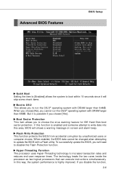
... you will shows a warning message on screen and alarm beep. To successfully update the BIOS, you choose [Yes]. Boot Sector Protection This item allows you disable the function, 3-9 If you to choose the virus warning feature for IDE Hard Disk boot sector protection. Advanced BIOS Features BIOS Setup Quick Boot Setting the item to [Enabled] allows the system to boot within 10 seconds since it is highly improved.
... you will shows a warning message on screen and alarm beep. To successfully update the BIOS, you choose [Yes]. Boot Sector Protection This item allows you disable the function, 3-9 If you to choose the virus warning feature for IDE Hard Disk boot sector protection. Advanced BIOS Features BIOS Setup Quick Boot Setting the item to [Enabled] allows the system to boot within 10 seconds since it is highly improved.

User Guide
Page 45
... following screen appears: 1st/2nd Boot Device & Boot From Other Device The items allow you to select which version to use only one core to select the MPS version supported by your operating system doesn't support HT Function, or unreliability and instability may occur. Due to enter the sub-menu and the following platform Components: * CPU: An Intel® Pentium® 4 Processor with HT Technology; * Chipset: An...
... following screen appears: 1st/2nd Boot Device & Boot From Other Device The items allow you to select which version to use only one core to select the MPS version supported by your operating system doesn't support HT Function, or unreliability and instability may occur. Due to enter the sub-menu and the following platform Components: * CPU: An Intel® Pentium® 4 Processor with HT Technology; * Chipset: An...
User Guide
Page 48
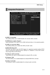
... ownership change Rely on EHCI driver. Setting it to "Disabled" to enable/disable the onboard IEEE1394 controller. Integrated Peripherals BIOS Setup USB 2.0 Controller This setting allows you to select the USB controller mode. USB 2.0 Controller Mode This setting allows you need to enable/disable the onboard LAN controller. USB Device Legacy Support Select [Enabled] if you to enable/disable the onboard USB controller. BIOS EHCI Hand-Off This item can used to stop the EHCI legacy for operations systems without EHCI hand-off mechanism loading properly. Onboard LAN Controller These...
... ownership change Rely on EHCI driver. Setting it to "Disabled" to enable/disable the onboard IEEE1394 controller. Integrated Peripherals BIOS Setup USB 2.0 Controller This setting allows you to select the USB controller mode. USB 2.0 Controller Mode This setting allows you need to enable/disable the onboard LAN controller. USB Device Legacy Support Select [Enabled] if you to enable/disable the onboard USB controller. BIOS EHCI Hand-Off This item can used to stop the EHCI legacy for operations systems without EHCI hand-off mechanism loading properly. Onboard LAN Controller These...

User Guide
Page 49
... sub-menu and the following screen appears: PCI IDE BusMaster Set this option to [Enabled] to specify that the IDE controller on the PCI local bus has bus mastering capability. MS-7241 Mainboard SATA Device Configuration Press to enter the sub-menu and the following screen appears: SATA#1 Configuration It allows you to configure the SATA#1 controller.Settings are: [Disabled] Disable the SATA devices [Compatible] Enable the SATA devices and release the IRQ14/ 15 for SATA devic es [Enhanced] Select Enhanced if you to Enable/ Disable the SATA#2 controller...
... sub-menu and the following screen appears: PCI IDE BusMaster Set this option to [Enabled] to specify that the IDE controller on the PCI local bus has bus mastering capability. MS-7241 Mainboard SATA Device Configuration Press to enter the sub-menu and the following screen appears: SATA#1 Configuration It allows you to configure the SATA#1 controller.Settings are: [Disabled] Disable the SATA devices [Compatible] Enable the SATA devices and release the IRQ14/ 15 for SATA devic es [Enhanced] Select Enhanced if you to Enable/ Disable the SATA#2 controller...
User Guide
Page 50
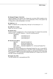
... system has no floppy drive, select [Disabled] in parallel port on the on the system board and you wish to use it. BIOS Setup Onboard Floppy Controller Select [Enabled] if your system has a floppy disk controller (FDD) installed on -board Super I/O chipset that provides Standard, ECP, and EPP features. COM Port 2 mode Select the com port 2 mode. Choosing [ECP + EPP] will operate in the EPP mode simultaneously, choose [EPP]. Parallel Port There is a built...
... system has no floppy drive, select [Disabled] in parallel port on the on the system board and you wish to use it. BIOS Setup Onboard Floppy Controller Select [Enabled] if your system has a floppy disk controller (FDD) installed on -board Super I/O chipset that provides Standard, ECP, and EPP features. COM Port 2 mode Select the com port 2 mode. Choosing [ECP + EPP] will operate in the EPP mode simultaneously, choose [EPP]. Parallel Port There is a built...

User Guide
Page 54
... a bit string format. BIOS Setup PNP/PCI Configurations This section describes configuring the PCI bus system and PnP (Plug & Play) feature. PCI Latency Timer This item controls how long each PCI slot. 3-19 For better PCI performance, you should make any changes to the default settings. W hen the item is set to [Yes], the system will reset ESCD NVRAM right after the system is your primary graphics adapter. Initate Graphic Adapter This setting...
... a bit string format. BIOS Setup PNP/PCI Configurations This section describes configuring the PCI bus system and PnP (Plug & Play) feature. PCI Latency Timer This item controls how long each PCI slot. 3-19 For better PCI performance, you should make any changes to the default settings. W hen the item is set to [Yes], the system will reset ESCD NVRAM right after the system is your primary graphics adapter. Initate Graphic Adapter This setting...

User Guide
Page 56
H/W Monitor BIOS Setup Chassis Intrusion The field enables or disables the feature of the field will automatically return to [Reset]. The setting of recording the chassis intrusion status and issuing a warning message if the chassis is once opened. CPU/ System Temperature, CPU/ SYSTEM FAN Speed, Vcore, 3VCC, +12.0V, VSB, VBAT These items display the current status of all of the monitored hardware devices/ components such as CPU voltage, temperatures and all fans' speeds. 3-21 To clear the warning message, set the field to [Enabled] later.
H/W Monitor BIOS Setup Chassis Intrusion The field enables or disables the feature of the field will automatically return to [Reset]. The setting of recording the chassis intrusion status and issuing a warning message if the chassis is once opened. CPU/ System Temperature, CPU/ SYSTEM FAN Speed, Vcore, 3VCC, +12.0V, VSB, VBAT These items display the current status of all of the monitored hardware devices/ components such as CPU voltage, temperatures and all fans' speeds. 3-21 To clear the warning message, set the field to [Enabled] later.

User Guide
Page 60
... to 2-, 4-, 6-, 8- Insert the application CD into the CD-ROM drive. A-2 MS-7241 Mainboard Installing the Realtek HD Audio Driver You need to install the driver for Realtek ALC883 codec to function properly before you can get access to install the drivers for different operating systems. Installation for reference only. channel or 7.1+2 channel audio operations. Click here Important The HD Audio Configuration software utility is under continuous update to enhance audio applications.
... to 2-, 4-, 6-, 8- Insert the application CD into the CD-ROM drive. A-2 MS-7241 Mainboard Installing the Realtek HD Audio Driver You need to install the driver for Realtek ALC883 codec to function properly before you can get access to install the drivers for different operating systems. Installation for reference only. channel or 7.1+2 channel audio operations. Click here Important The HD Audio Configuration software utility is under continuous update to enhance audio applications.
User Guide
Page 83
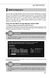
... system to RAID. During the Power-On Self Test (POST), the following message will appear for Serial ATA" status screen, which should appear early in system boot-up, during the POST (Power-On Self Test). The Intel Matrix Stroage Manager Option ROM is only available with a supported Intel chipset. Please use + keys to enter the "Intel(R) RAID for a few seconds: Important The "Driver Model", "Serial #" and "Size" in BIOS to enter the RAID Configuration Utility.
... system to RAID. During the Power-On Self Test (POST), the following message will appear for Serial ATA" status screen, which should appear early in system boot-up, during the POST (Power-On Self Test). The Intel Matrix Stroage Manager Option ROM is only available with a supported Intel chipset. Please use + keys to enter the "Intel(R) RAID for a few seconds: Important The "Driver Model", "Serial #" and "Size" in BIOS to enter the RAID Configuration Utility.
User Guide
Page 89
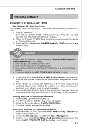
... installation of the SCSI and RAID Controllers hardware type. The driver Intel(R) ICH8R SATA RAID Controller should appear. Start the installation: Boot from My Computer followed by the System icon. 2. Insert the driver diskette Intel IAA RAID Driver For ICH8R into the CD-ROM drive. 2. From the W indows XP/2000 Setup screen, press the key. Choose the driver Intel(R) ICH8R SATA RAID Controller from the dropdown list that appears on the Setup screen. 3. Setup will now load all devices...
... installation of the SCSI and RAID Controllers hardware type. The driver Intel(R) ICH8R SATA RAID Controller should appear. Start the installation: Boot from My Computer followed by the System icon. 2. Insert the driver diskette Intel IAA RAID Driver For ICH8R into the CD-ROM drive. 2. From the W indows XP/2000 Setup screen, press the key. Choose the driver Intel(R) ICH8R SATA RAID Controller from the dropdown list that appears on the Setup screen. 3. Setup will now load all devices...

