User Manual
Page 12
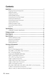
... Information 2 Installing a Processor 3 Installing DDR4 memory 4 Connecting the Front Panel Header 5 Installing the Motherboard 6 Connecting the Power Connectors 7 Installing SATA Drives 8 Installing a Graphics Card 9 Connecting Peripheral Devices 10 Power On...11 Specifications...15 JCORSAIR1 Connector Specification 20 Package contents 21 Block Diagram ...22 Rear I/O Panel...23 LAN Port LED Status Table 23 Audio Ports Configuration 23 Realtek Audio Console 24 Installing Antennas 26 Overview of Components 27 CPU Socket...29 DIMM Slots...32 PCI_E1~4: PCIe Expansion Slots 34...
... Information 2 Installing a Processor 3 Installing DDR4 memory 4 Connecting the Front Panel Header 5 Installing the Motherboard 6 Connecting the Power Connectors 7 Installing SATA Drives 8 Installing a Graphics Card 9 Connecting Peripheral Devices 10 Power On...11 Specifications...15 JCORSAIR1 Connector Specification 20 Package contents 21 Block Diagram ...22 Rear I/O Panel...23 LAN Port LED Status Table 23 Audio Ports Configuration 23 Realtek Audio Console 24 Installing Antennas 26 Overview of Components 27 CPU Socket...29 DIMM Slots...32 PCI_E1~4: PCIe Expansion Slots 34...
User Manual
Page 13
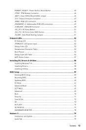
... LED connectors 49 JCORSAIR1: CORSAIR Connector 50 JOC_RT1: OC Retry Button 51 JOC_FS1: OC Force Enter BIOS Button 51 JSLOW1: Slow Mode Booting Jumper 51 Onboard LEDs...52 EZ Debug LED...52 JPWRLED1: LED power input 52 Debug Code LED...53 Hexadecimal Character Table 53 Boot Phases...53 Debug Code LED Table 53 ACPI States Codes 57 Installing OS, Drivers & Utilities 58 Installing Windows® 10 58 Installing Drivers 58 Installing Utilities 58 BIOS Setup...59 Entering BIOS Setup 59 Resetting BIOS...60 Updating BIOS...60 EZ Mode...62 Advanced Mode ...64 SETTINGS...
... LED connectors 49 JCORSAIR1: CORSAIR Connector 50 JOC_RT1: OC Retry Button 51 JOC_FS1: OC Force Enter BIOS Button 51 JSLOW1: Slow Mode Booting Jumper 51 Onboard LEDs...52 EZ Debug LED...52 JPWRLED1: LED power input 52 Debug Code LED...53 Hexadecimal Character Table 53 Boot Phases...53 Debug Code LED Table 53 ACPI States Codes 57 Installing OS, Drivers & Utilities 58 Installing Windows® 10 58 Installing Drivers 58 Installing Utilities 58 BIOS Setup...59 Entering BIOS Setup 59 Resetting BIOS...60 Updating BIOS...60 EZ Mode...62 Advanced Mode ...64 SETTINGS...

User Manual
Page 17
Internal Connectors Internal Buttons Debug LED I/O Controller Continued from previous page ∙∙1x 24-pin ATX main power connector ∙∙2x 8-pin ATX 12V power connectors ∙∙6x SATA 6Gb/s connectors ∙∙3x M.2 slots (M-Key) ∙∙1x USB 3.2 Gen2 Type-C port ∙∙2x USB 3.2 Gen1 connectors (supports additional 4 USB 3.2 Gen1 ports) ∙∙2x USB 2.0 connectors (supports additional 4 USB 2.0 ports) ∙∙1x 4-pin CPU fan connector ∙∙1x 4-pin pump fan connector (supports up to 2A) ∙∙4x 4-pin system fan ...
Internal Connectors Internal Buttons Debug LED I/O Controller Continued from previous page ∙∙1x 24-pin ATX main power connector ∙∙2x 8-pin ATX 12V power connectors ∙∙6x SATA 6Gb/s connectors ∙∙3x M.2 slots (M-Key) ∙∙1x USB 3.2 Gen2 Type-C port ∙∙2x USB 3.2 Gen1 connectors (supports additional 4 USB 3.2 Gen1 ports) ∙∙2x USB 2.0 connectors (supports additional 4 USB 2.0 ports) ∙∙1x 4-pin CPU fan connector ∙∙1x 4-pin pump fan connector (supports up to 2A) ∙∙4x 4-pin system fan ...
User Manual
Page 18
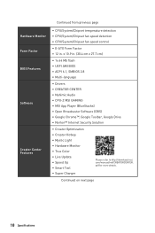
.... Hardware Monitor Form Factor BIOS Features Software Creator Center Features Continued from previous page ∙∙CPU/System/Chipset temperature detection ∙∙CPU/System/Chipset fan speed detection ∙∙CPU/System/Chipset fan speed control ∙∙E-ATX Form Factor ∙∙12 in . (30.4 cm x 27.7 cm) ∙∙1x 64 Mb flash ∙∙UEFI AMI BIOS ∙∙ACPI 6.1, SMBIOS 2.8 ∙∙ Multi-language ∙∙ Drivers...
.... Hardware Monitor Form Factor BIOS Features Software Creator Center Features Continued from previous page ∙∙CPU/System/Chipset temperature detection ∙∙CPU/System/Chipset fan speed detection ∙∙CPU/System/Chipset fan speed control ∙∙E-ATX Form Factor ∙∙12 in . (30.4 cm x 27.7 cm) ∙∙1x 64 Mb flash ∙∙UEFI AMI BIOS ∙∙ACPI 6.1, SMBIOS 2.8 ∙∙ Multi-language ∙∙ Drivers...
User Manual
Page 20
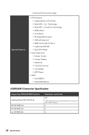
...;AMD Turbo USB 3.2 Gen 2 ▪▪Lightning USB 20G ▪▪Dual CPU Power ∙∙User Experience ▪▪Creator Center ▪▪Creator Hotkey ▪▪Speed Up ▪▪Total Fan Control ▪▪Live Update ▪▪APP Player ∙∙ BIOS ▪▪Click BIOS 5 ▪▪Flash BIOS Button JCORSAIR1 Connector Specification Supporting CORSAIR RGB Products Lighting Node PRO LED Strip HD120 RGB Fan SP120 RGB Fan LL120 RGB Fan Maximum connection...
...;AMD Turbo USB 3.2 Gen 2 ▪▪Lightning USB 20G ▪▪Dual CPU Power ∙∙User Experience ▪▪Creator Center ▪▪Creator Hotkey ▪▪Speed Up ▪▪Total Fan Control ▪▪Live Update ▪▪APP Player ∙∙ BIOS ▪▪Click BIOS 5 ▪▪Flash BIOS Button JCORSAIR1 Connector Specification Supporting CORSAIR RGB Products Lighting Node PRO LED Strip HD120 RGB Fan SP120 RGB Fan LL120 RGB Fan Maximum connection...

User Manual
Page 49
... JRAINBOW connector provide different voltages, and connecting the 5V LED strip to the JRGB connector will result in damage to the LED strip. ⚠⚠Important ∙∙The JRAINBOW connector supports up to 200 LEDs. ∙∙Always turn off the power supply and unplug the power cord from the power outlet before installing or removing the RGB LED strip. ∙∙Please use MSI's software to 75 LEDs WS2812B...
... JRAINBOW connector provide different voltages, and connecting the 5V LED strip to the JRGB connector will result in damage to the LED strip. ⚠⚠Important ∙∙The JRAINBOW connector supports up to 200 LEDs. ∙∙Always turn off the power supply and unplug the power cord from the power outlet before installing or removing the RGB LED strip. ∙∙Please use MSI's software to 75 LEDs WS2812B...

User Manual
Page 54
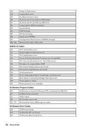
... Mode (SMM) initialization Post-Memory System Agent initialization is started Post-Memory System Agent initialization (System Agent module specific) Post-Memory PCH initialization is started Post-Memory PCH initialization (PCH module specific) DXE IPL is started PEI Error Codes 4B Memory not installed (For Summit CPU) E0 Memory not installed (For Bristol CPU) DXE Progress Codes 60 DXE Core is started 61 NVRAM initialization 62 Installation of the PCH Runtime Services 63 CPU DXE initialization is started 54 Onboard LEDs Application Processor...
... Mode (SMM) initialization Post-Memory System Agent initialization is started Post-Memory System Agent initialization (System Agent module specific) Post-Memory PCH initialization is started Post-Memory PCH initialization (PCH module specific) DXE IPL is started PEI Error Codes 4B Memory not installed (For Summit CPU) E0 Memory not installed (For Bristol CPU) DXE Progress Codes 60 DXE Core is started 61 NVRAM initialization 62 Installation of the PCH Runtime Services 63 CPU DXE initialization is started 54 Onboard LEDs Application Processor...
User Manual
Page 56
... End Legacy Option ROM Initialization System Reset USB hot plug PCI bus hot plug Clean-up of NVRAM Configuration Reset (reset of the Architectural Protocols are not available D4 PCI resource allocation error. Out of Resources D5 No Space for Legacy Option ROM D6 No Console Output Devices are found D7 No Console Input Devices are found D8 Invalid password D9 Error loading Boot Option (LoadImage returned error) DA Boot Option is failed (StartImage returned error) DB Flash update is...
... End Legacy Option ROM Initialization System Reset USB hot plug PCI bus hot plug Clean-up of NVRAM Configuration Reset (reset of the Architectural Protocols are not available D4 PCI resource allocation error. Out of Resources D5 No Space for Legacy Option ROM D6 No Console Output Devices are found D7 No Console Input Devices are found D8 Invalid password D9 Error loading Boot Option (LoadImage returned error) DA Boot Option is failed (StartImage returned error) DB Flash update is...
User Manual
Page 58
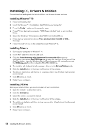
... button on the screen to open the installer. Installing Drivers 1. Click OK button to finish. 7. Open the installer as described above. 2. Press F11 key during the computer POST (Power-On Self Test) to boot from the Windows Control Panel, you to choose what happens with removable drives pop-up your computer. Insert MSI® USB Drive into Boot Menu. 5. The drivers installation will then be in the Drivers/Software tab. 5. Click the Utilities tab. 3. Installing Utilities Before you install utilities...
... button on the screen to open the installer. Installing Drivers 1. Click OK button to finish. 7. Open the installer as described above. 2. Press F11 key during the computer POST (Power-On Self Test) to boot from the Windows Control Panel, you to choose what happens with removable drives pop-up your computer. Insert MSI® USB Drive into Boot Menu. 5. The drivers installation will then be in the Drivers/Software tab. 5. Click the Utilities tab. 3. Installing Utilities Before you install utilities...
User Manual
Page 60
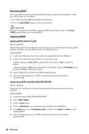
Updating BIOS: 1. After the flashing process is set properly. Install and launch MSI CREATOR CENTER. 2. Click Next and choose In Windows mode. Updating BIOS: 1. Insert the USB flash drive that matches your motherboard model from MSI website. Updating BIOS Updating BIOS with MSI CREATOR CENTER Before updating: Make sure the LAN driver is already installed and the Internet connection is 100% completed, the system will restart automatically. 60 BIOS Setup Click the M-FLASH button and click on Yes to download and install the latest BIOS file. 5. Click...
Updating BIOS: 1. After the flashing process is set properly. Install and launch MSI CREATOR CENTER. 2. Click Next and choose In Windows mode. Updating BIOS: 1. Insert the USB flash drive that matches your motherboard model from MSI website. Updating BIOS Updating BIOS with MSI CREATOR CENTER Before updating: Make sure the LAN driver is already installed and the Internet connection is 100% completed, the system will restart automatically. 60 BIOS Setup Click the M-FLASH button and click on Yes to download and install the latest BIOS file. 5. Click...
User Manual
Page 61
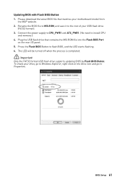
... power supply to CPU_PWR1 and ATX_PWR1. (No need to flash BIOS, and the LED starts flashing. 6. Plug the USB flash drive that matches your motherboard model from the MSI® website. 2. Please download the latest BIOS file that contains the MSI.ROM file into the Flash BIOS Port on the drive icon and go to Properties. The LED will be turned off when the process is completed. ⚠⚠Important Only the FAT32 format USB flash drive supports updating BIOS by Flash BIOS Button. Updating BIOS with Flash BIOS Button...
... power supply to CPU_PWR1 and ATX_PWR1. (No need to flash BIOS, and the LED starts flashing. 6. Plug the USB flash drive that matches your motherboard model from the MSI® website. 2. Please download the latest BIOS file that contains the MSI.ROM file into the Flash BIOS Port on the drive icon and go to Properties. The LED will be turned off when the process is completed. ⚠⚠Important Only the FAT32 format USB flash drive supports updating BIOS by Flash BIOS Button. Updating BIOS with Flash BIOS Button...
User Manual
Page 62
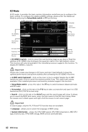
... the installed processor supports this tab or the F12 key to enable/ disable the A-XMP. A-XMP switch Setup Mode switch Screenshot Language System information OC GENIE 4 switch Information display Boot device priority bar M-Flash Favorites Hardware Monitor Function buttons ∙∙ OC GENIE 4 switch - It allows you to select the language of OC GENIE 4 by clicking on this function. To configure the advanced BIOS settings, please enter the Advanced Mode by BIOS item name, enter...
... the installed processor supports this tab or the F12 key to enable/ disable the A-XMP. A-XMP switch Setup Mode switch Screenshot Language System information OC GENIE 4 switch Information display Boot device priority bar M-Flash Favorites Hardware Monitor Function buttons ∙∙ OC GENIE 4 switch - It allows you to select the language of OC GENIE 4 by clicking on this function. To configure the advanced BIOS settings, please enter the Advanced Mode by BIOS item name, enter...
User Manual
Page 66
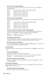
... as LAN, HDD, USB and audio. The options in above 4G address space. This item will appear when Above 4G memory/Crypto Currency mining is enabled. ▶▶PCIe SlotX Lanes Configuration PCIe lanes configuration is only available if the system supports 64-bit PCI decoding. [Enabled] Allows you to enter the sub-menu. ▶▶Onboard LAN Controller [Enabled] Enables or disables the onboard LAN controller. 66 BIOS Setup Press Enter to utilize more than 4x GPUs. [Disabled] Disables this item...
... as LAN, HDD, USB and audio. The options in above 4G address space. This item will appear when Above 4G memory/Crypto Currency mining is enabled. ▶▶PCIe SlotX Lanes Configuration PCIe lanes configuration is only available if the system supports 64-bit PCI decoding. [Enabled] Allows you to enter the sub-menu. ▶▶Onboard LAN Controller [Enabled] Enables or disables the onboard LAN controller. 66 BIOS Setup Press Enter to utilize more than 4x GPUs. [Disabled] Disables this item...
User Manual
Page 67
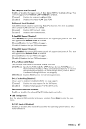
... LAN Boot ROM. ▶▶Network Stack [Disabled] Sets UEFI network stack for optimizing IPv4 / IPv6 function. AHCI (Advanced Host Controller Interface) offers some advanced features to enhance the speed and performance of the onboard SATA controller. [AHCI Mode] Specify the AHCI mode for the SATA ports. ▶▶HD Audio Controller [Enabled] Enables or disables the onboard High Definition Audio controller. ▶▶USB Configuration Sets the onboard USB controller and device function. BIOS Setup 67 Press Enter to enable or disable the SATA hot plug support. [Enabled...
... LAN Boot ROM. ▶▶Network Stack [Disabled] Sets UEFI network stack for optimizing IPv4 / IPv6 function. AHCI (Advanced Host Controller Interface) offers some advanced features to enhance the speed and performance of the onboard SATA controller. [AHCI Mode] Specify the AHCI mode for the SATA ports. ▶▶HD Audio Controller [Enabled] Enables or disables the onboard High Definition Audio controller. ▶▶USB Configuration Sets the onboard USB controller and device function. BIOS Setup 67 Press Enter to enable or disable the SATA hot plug support. [Enabled...

User Manual
Page 68
... wake up by USB and PCIe devices. [Disabled] Disables this function. ▶▶Windows OS Configuration Sets Windows detailed configuration and behaviors. ▶▶Legacy USB Support [Enabled] Sets Legacy USB function support. [Auto] The system will automatically detect if any USB device is connected and enable the legacy USB support. [Enabled] Enable the USB support under legacy mode. ▶▶Power Management Setup Sets system Power Management of ErP Ready and AC Power Loss behaviors. Press Enter to enter the submenu. ▶▶BIOS UEFI/CSM Mode [UEFI] Select...
... wake up by USB and PCIe devices. [Disabled] Disables this function. ▶▶Windows OS Configuration Sets Windows detailed configuration and behaviors. ▶▶Legacy USB Support [Enabled] Sets Legacy USB function support. [Auto] The system will automatically detect if any USB device is connected and enable the legacy USB support. [Enabled] Enable the USB support under legacy mode. ▶▶Power Management Setup Sets system Power Management of ErP Ready and AC Power Loss behaviors. Press Enter to enter the submenu. ▶▶BIOS UEFI/CSM Mode [UEFI] Select...

User Manual
Page 69
... events will be awakened from the power saving modes when activity or input signal of PCI/ PCIe device is set wake up events of these fields (using the + and - If Resume By RTC Alarm is detected. [Disabled] Disables this function. ▶▶Date (of installed PCI/ PCI-E expansion cards, integrated LAN controllers or USB devices which are supported by third party integrated chips. [Enabled] Enables the system to be defined by OS...
... events will be awakened from the power saving modes when activity or input signal of PCI/ PCIe device is set wake up events of these fields (using the + and - If Resume By RTC Alarm is detected. [Disabled] Disables this function. ▶▶Date (of installed PCI/ PCI-E expansion cards, integrated LAN controllers or USB devices which are supported by third party integrated chips. [Enabled] Enables the system to be defined by OS...
User Manual
Page 74
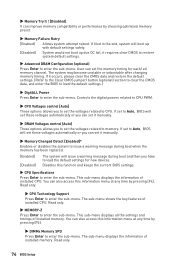
... the default settings. (Refer to the Clear CMOS jumper/ button (optional) section to clear the CMOS data, and enter the BIOS to load the default settings.) ▶▶DigitALL Power Press Enter to enter the sub-menu. Read only. ▶▶CPU Technology Support Press Enter to CPU. Read only. 74 BIOS Setup Controls the digital powers related to CPU PWM. ▶▶CPU Voltages control [Auto] These options allows you to set the voltages related to enter the sub-menu. This sub-menu displays the information of installed memory. The...
... the default settings. (Refer to the Clear CMOS jumper/ button (optional) section to clear the CMOS data, and enter the BIOS to load the default settings.) ▶▶DigitALL Power Press Enter to enter the sub-menu. Read only. ▶▶CPU Technology Support Press Enter to CPU. Read only. 74 BIOS Setup Controls the digital powers related to CPU PWM. ▶▶CPU Voltages control [Auto] These options allows you to set the voltages related to enter the sub-menu. This sub-menu displays the information of installed memory. The...
User Manual
Page 79
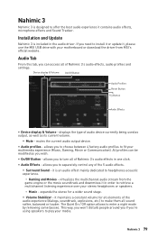
... - The Quiet On / Off option allows to install it or update it contains audio effects, microphone effects and Sound Tracker. If you 're using speakers to play your media. mutes the current audio output device. ∙∙ Audio profiles - Nahimic 3 Nahimic 3 is designed to offer the best audio experience it , please use the MSI USB drive with your motherboard or download the driver from the game engine or...
... - The Quiet On / Off option allows to install it or update it contains audio effects, microphone effects and Sound Tracker. If you 're using speakers to play your media. mutes the current audio output device. ∙∙ Audio profiles - Nahimic 3 Nahimic 3 is designed to offer the best audio experience it , please use the MSI USB drive with your motherboard or download the driver from the game engine or...
User Manual
Page 86
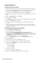
... USB port. 3. Select the (rcbottom.inf) driver, click Next. 5. Leave the USB drive in BIOS 2. Insert the MSI USB Drive into the RAIDXpert2 Web GUI with removable drives pop-up notification, then select Run DVDSetup.exe to install a third party RAID driver. 2. Under the Drivers/Software tab, check the AMD RAID Drivers check-box. 5. admin 9. Click the Install button. 6. admin ▫▫Password - When prompted, click OK. 6. Windows setup will need to copy the files...
... USB port. 3. Select the (rcbottom.inf) driver, click Next. 5. Leave the USB drive in BIOS 2. Insert the MSI USB Drive into the RAIDXpert2 Web GUI with removable drives pop-up notification, then select Run DVDSetup.exe to install a third party RAID driver. 2. Under the Drivers/Software tab, check the AMD RAID Drivers check-box. 5. admin 9. Click the Install button. 6. admin ▫▫Password - When prompted, click OK. 6. Windows setup will need to copy the files...
User Manual
Page 87
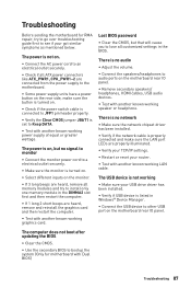
... button is turned on. ∙∙Check if the power switch cable is connected to JFP1 pin header properly. ∙∙Verify the Clear CMOS jumper JBAT1 is listed in the BIOS. The computer does not boot after updating the BIOS ∙∙Clear the CMOS. ∙∙Use the secondary BIOS to install only one memory module in the DIMMA2 slot first and then restart the computer. ∙∙If 1 long 2 short beeps are heard, remove...
... button is turned on. ∙∙Check if the power switch cable is connected to JFP1 pin header properly. ∙∙Verify the Clear CMOS jumper JBAT1 is listed in the BIOS. The computer does not boot after updating the BIOS ∙∙Clear the CMOS. ∙∙Use the secondary BIOS to install only one memory module in the DIMMA2 slot first and then restart the computer. ∙∙If 1 long 2 short beeps are heard, remove...


