User Manual
Page 1
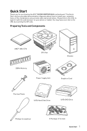
... Components AMD® AM4 CPU CPU Fan Chassis DDR4 Memory Power Supply Unit Graphics Card Thermal Paste SATA Hard Disk Drive SATA DVD Drive Phillips Screwdriver A Package of the installations also provide video demonstrations. Please link to the URL to install your phone or tablet. This Quick Start section provides demonstration diagrams about how to watch it with the web browser on your computer. Quick Start Thank you for purchasing the MSI® B450M MORTAR MAX motherboard. You...
... Components AMD® AM4 CPU CPU Fan Chassis DDR4 Memory Power Supply Unit Graphics Card Thermal Paste SATA Hard Disk Drive SATA DVD Drive Phillips Screwdriver A Package of the installations also provide video demonstrations. Please link to the URL to install your phone or tablet. This Quick Start section provides demonstration diagrams about how to watch it with the web browser on your computer. Quick Start Thank you for purchasing the MSI® B450M MORTAR MAX motherboard. You...
User Manual
Page 12
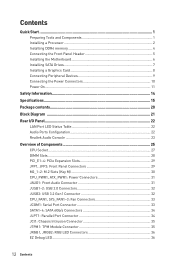
... Quick Start ...1 Preparing Tools and Components 1 Installing a Processor 2 Installing DDR4 memory 4 Connecting the Front Panel Header 5 Installing the Motherboard 6 Installing SATA Drives 7 Installing a Graphics Card 8 Connecting Peripheral Devices 9 Connecting the Power Connectors 10 Power On...11 Safety Information 14 Specifications...15 Package contents 20 Block Diagram ...21 Rear I/O Panel...22 LAN Port LED Status Table 22 Audio Ports Configuration 22 Realtek Audio Console 23 Overview of Components 25 CPU Socket ...27 DIMM Slots...28 PCI_E1~4: PCIe Expansion Slots 29...
... Quick Start ...1 Preparing Tools and Components 1 Installing a Processor 2 Installing DDR4 memory 4 Connecting the Front Panel Header 5 Installing the Motherboard 6 Installing SATA Drives 7 Installing a Graphics Card 8 Connecting Peripheral Devices 9 Connecting the Power Connectors 10 Power On...11 Safety Information 14 Specifications...15 Package contents 20 Block Diagram ...21 Rear I/O Panel...22 LAN Port LED Status Table 22 Audio Ports Configuration 22 Realtek Audio Console 23 Overview of Components 25 CPU Socket ...27 DIMM Slots...28 PCI_E1~4: PCIe Expansion Slots 29...
User Manual
Page 13
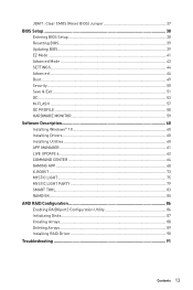
JBAT1: Clear CMOS (Reset BIOS) Jumper 37 BIOS Setup ...38 Entering BIOS Setup 38 Resetting BIOS...39 Updating BIOS...39 EZ Mode ...41 Advanced Mode ...43 SETTINGS...44 Advanced...44 Boot...49 Security ...50 Save & Exit...51 OC...53 M-FLASH ...57 OC PROFILE ...58 HARDWARE MONITOR 59 Software Description 60 Installing Windows® 10 60 Installing Drivers 60 Installing Utilities 60 APP MANAGER ...61 LIVE UPDATE 6...62 COMMAND CENTER 64 GAMING APP...68 X-BOOST ...73 MYSTIC LIGHT...75 MYSTIC LIGHT PARTY...
JBAT1: Clear CMOS (Reset BIOS) Jumper 37 BIOS Setup ...38 Entering BIOS Setup 38 Resetting BIOS...39 Updating BIOS...39 EZ Mode ...41 Advanced Mode ...43 SETTINGS...44 Advanced...44 Boot...49 Security ...50 Save & Exit...51 OC...53 M-FLASH ...57 OC PROFILE ...58 HARDWARE MONITOR 59 Software Description 60 Installing Windows® 10 60 Installing Drivers 60 Installing Utilities 60 APP MANAGER ...61 LIVE UPDATE 6...62 COMMAND CENTER 64 GAMING APP...68 X-BOOST ...73 MYSTIC LIGHT...75 MYSTIC LIGHT PARTY...
User Manual
Page 29
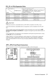
... installed in the PCI_E3 slot. Power LED Power Switch - -+ -- ++ JFP1 2 1 + 10 9 Reserved HDD LED Reset Switch 1 HDD LED + 2 3 HDD LED - 4 5 Reset Switch 6 7 Reset Switch 8 9 Reserved 10 Power LED + Power LED Power Switch Power Switch No Pin Overview of the slot. y If you install a large and heavy graphics card, you need to use a tool such as MSI Gaming Series Graphics Card Bolster to support its weight to prevent deformation of Components 29 PCI_E1~4: PCIe Expansion Slots Processors RYZEN Series Slots PCI_E1 PCIe 3.0 x16 PCI_E2 PCIe 2.0 x1 PCI_E3 PCIe...
... installed in the PCI_E3 slot. Power LED Power Switch - -+ -- ++ JFP1 2 1 + 10 9 Reserved HDD LED Reset Switch 1 HDD LED + 2 3 HDD LED - 4 5 Reset Switch 6 7 Reset Switch 8 9 Reserved 10 Power LED + Power LED Power Switch Power Switch No Pin Overview of the slot. y If you install a large and heavy graphics card, you need to use a tool such as MSI Gaming Series Graphics Card Bolster to support its weight to prevent deformation of Components 29 PCI_E1~4: PCIe Expansion Slots Processors RYZEN Series Slots PCI_E1 PCIe 3.0 x16 PCI_E2 PCIe 2.0 x1 PCI_E3 PCIe...
User Manual
Page 39
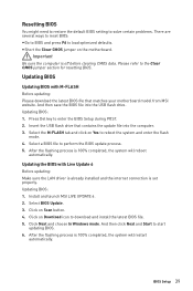
... the USB flash drive. Install and launch MSI LIVE UPDATE 6. 2. And then click Next and Start to perform the BIOS update process. 5. Updating BIOS Updating BIOS with Live Update 6 Before updating: Make sure the LAN driver is already installed and the internet connection is off before clearing CMOS data. Updating BIOS: 1. Select BIOS Update. 3. Click on Scan button. 4. Updating BIOS: 1. Select a BIOS file to start updating BIOS. 6. Click Next and choose In Windows mode. BIOS Setup 39 Press Del key to download and install the latest BIOS file. 5. Click on Download icon to enter...
... the USB flash drive. Install and launch MSI LIVE UPDATE 6. 2. And then click Next and Start to perform the BIOS update process. 5. Updating BIOS Updating BIOS with Live Update 6 Before updating: Make sure the LAN driver is already installed and the internet connection is off before clearing CMOS data. Updating BIOS: 1. Select BIOS Update. 3. Click on Scan button. 4. Updating BIOS: 1. Select a BIOS file to start updating BIOS. 6. Click Next and choose In Windows mode. BIOS Setup 39 Press Del key to download and install the latest BIOS file. 5. Click on Download icon to enter...
User Manual
Page 41
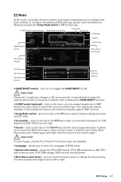
... the F7 key to switch between Advanced mode and EZ mode. y Search - The boot priority from high to low is left to USB flash drive (FAT/ FAT32 format only). A-XMP switch Setup Mode switch Screenshot Search Language System information GAME BOOST switch Boot device priority bar Information display M-Flash Favorites Hardware Monitor Function buttons y GAME BOOST switch - Switch the outer circle to select the memory profile if any changes in OC menu and don't load defaults to...
... the F7 key to switch between Advanced mode and EZ mode. y Search - The boot priority from high to low is left to USB flash drive (FAT/ FAT32 format only). A-XMP switch Setup Mode switch Screenshot Search Language System information GAME BOOST switch Boot device priority bar Information display M-Flash Favorites Hardware Monitor Function buttons y GAME BOOST switch - Switch the outer circle to select the memory profile if any changes in OC menu and don't load defaults to...
User Manual
Page 42
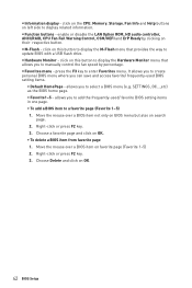
... left side to enter Favorites menu. It allows you to create personal BIOS menu where you to a favorite page (Favorite 1~5) 1. SETTINGS, OC...,etc) as the BIOS home page. ƒ Favorite1~5 - Right-click or press F2 key. 3. y Information display - enable or disable the LAN Option ROM, HD audio controller, AHCI/RAID, CPU Fan Fail Warning Control, CSM/UEFI and ErP Ready by percentage. y Hardware Monitor - Right-click or press F2 key. 3. y Favorites menu - Choose a favorite...
... left side to enter Favorites menu. It allows you to create personal BIOS menu where you to a favorite page (Favorite 1~5) 1. SETTINGS, OC...,etc) as the BIOS home page. ƒ Favorite1~5 - Right-click or press F2 key. 3. y Information display - enable or disable the LAN Option ROM, HD audio controller, AHCI/RAID, CPU Fan Fail Warning Control, CSM/UEFI and ErP Ready by percentage. y Hardware Monitor - Right-click or press F2 key. 3. y Favorites menu - Choose a favorite...
User Manual
Page 45
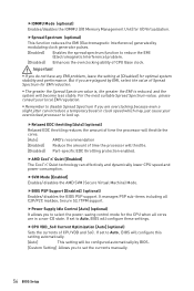
... M.2 PCIe storage card. BIOS Setup 45 f Integrated Peripherals Sets integrated peripherals' parameters, such as LAN, HDD, USB and audio. fLAN Option ROM [Disabled] Enables or disables the legacy network Boot Option ROM for optimizing IPv4 / IPv6 function. Press Enter to enter the submenu. The options in above 4G address space. fPower LED [Blinking] Sets shining behaviors of onboard power LED behaviors. This item is available when Onboard LAN Controller is only available if the system supports 64-bit PCI decoding. [Enabled] Allows you to utilize more...
... M.2 PCIe storage card. BIOS Setup 45 f Integrated Peripherals Sets integrated peripherals' parameters, such as LAN, HDD, USB and audio. fLAN Option ROM [Disabled] Enables or disables the legacy network Boot Option ROM for optimizing IPv4 / IPv6 function. Press Enter to enter the submenu. The options in above 4G address space. fPower LED [Blinking] Sets shining behaviors of onboard power LED behaviors. This item is available when Onboard LAN Controller is only available if the system supports 64-bit PCI decoding. [Enabled] Allows you to utilize more...
User Manual
Page 46
... user to enhance the speed and performance of SATA storage device, such as the primary boot device. [IGD] Integrated Graphics Display. [PEG] PCI-Express Graphics Device. AHCI (Advanced Host Controller Interface) offers some advanced features to enable or disable the SATA hot plug support. [Enabled] Enables hot plug support for the SATA ports. [Disabled] Disables hot plug support for SATA storage devices. This item will be unavailable under legacy mode. [Disabled] The USB devices will enable the integrated graphics controller. fInitiate Graphic Adapter [PEG] (optional...
... user to enhance the speed and performance of SATA storage device, such as the primary boot device. [IGD] Integrated Graphics Display. [PEG] PCI-Express Graphics Device. AHCI (Advanced Host Controller Interface) offers some advanced features to enable or disable the SATA hot plug support. [Enabled] Enables hot plug support for the SATA ports. [Disabled] Disables hot plug support for SATA storage devices. This item will be unavailable under legacy mode. [Disabled] The USB devices will enable the integrated graphics controller. fInitiate Graphic Adapter [PEG] (optional...
User Manual
Page 47
...-1.9 and SPP Mode] Enhanced Parallel Port-1.9 mode + Standard Parallel Port mode. If set to Auto, BIOS will optimize the IRQ automatically or you can set to Auto, BIOS will not support S4 & S5 wake up the system after restoring AC power. [Power On] Boot up by USB, PCI and PCIe devices. [Disabled] Disables this function. fParallel (LPT) Port [Enabled] Enables or disables parallel(LPT/ LPTE) port. BIOS Setup 47 fSerial Port [Enabled] Enables or disables serial port. f Power Management Setup Sets system Power Management of serial(COM) port 0. Press Enter to the...
...-1.9 and SPP Mode] Enhanced Parallel Port-1.9 mode + Standard Parallel Port mode. If set to Auto, BIOS will optimize the IRQ automatically or you can set to Auto, BIOS will not support S4 & S5 wake up the system after restoring AC power. [Power On] Boot up by USB, PCI and PCIe devices. [Disabled] Disables this function. fParallel (LPT) Port [Enabled] Enables or disables parallel(LPT/ LPTE) port. BIOS Setup 47 fSerial Port [Enabled] Enables or disables serial port. f Power Management Setup Sets system Power Management of serial(COM) port 0. Press Enter to the...
User Manual
Page 48
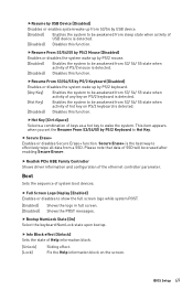
...-menu will appear when BIOS UEFI/CSM Mode is enabled. fResume By RTC Alarm [Disabled] Disables or enables the system wake up by OS. f Windows OS Configuration Sets Windows detailed configuration and behaviors. f Wake Up Event Setup Sets system wake up when detecting abnormal voltage input. [Enabled] Protect the system from the power saving modes when activity or input signal of installed PCI-E expansion cards, integrated LAN controllers or USB devices which are supported...
...-menu will appear when BIOS UEFI/CSM Mode is enabled. fResume By RTC Alarm [Disabled] Disables or enables the system wake up by OS. f Windows OS Configuration Sets Windows detailed configuration and behaviors. f Wake Up Event Setup Sets system wake up when detecting abnormal voltage input. [Enabled] Protect the system from the power saving modes when activity or input signal of installed PCI-E expansion cards, integrated LAN controllers or USB devices which are supported...
User Manual
Page 49
... Hot Key. f Bootup NumLock State [On] Select the keyboard NumLock state upon bootup. Secure Erase+ is detected. [Disabled] Disables this function. f Full Screen Logo Display [Enabled] Enables or disables to show the full screen logo while system POST. [Enabled] Shows the logo in full screen. [Disabled] Shows the POST messages. fResume by USB Device [Disabled] Disables or enables system wake up from S3/S4 by USB device. [Enabled] Enables the system to be awakened from sleep...
... Hot Key. f Bootup NumLock State [On] Select the keyboard NumLock state upon bootup. Secure Erase+ is detected. [Disabled] Disables this function. f Full Screen Logo Display [Enabled] Enables or disables to show the full screen logo while system POST. [Enabled] Shows the logo in full screen. [Disabled] Shows the POST messages. fResume by USB Device [Disabled] Disables or enables system wake up from S3/S4 by USB device. [Enabled] Enables the system to be awakened from sleep...
User Manual
Page 51
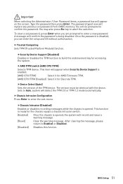
... the chassis is opened . fSecurity Device Support [Disabled] Enables or disables the TPM function to Enabled or Disabled. [Disabled] Disables this funcion. fAMD fTPM switch [AMD CPU fTPM] Selects TPM device. This item will confirm the password is enabled. [AMD CPU fTPM] Select it for AMD Firmware TPM. [AMD CPU fTPM Disabled] Select it for Discrete TPM. BIOS Setup 51 A message will appear when Security Device Support is being disabled. Type the password then press Enter. This function is ready for accessing...
... the chassis is opened . fSecurity Device Support [Disabled] Enables or disables the TPM function to Enabled or Disabled. [Disabled] Disables this funcion. fAMD fTPM switch [AMD CPU fTPM] Selects TPM device. This item will confirm the password is enabled. [AMD CPU fTPM] Select it for AMD Firmware TPM. [AMD CPU fTPM Disabled] Select it for Discrete TPM. BIOS Setup 51 A message will appear when Security Device Support is being disabled. Type the password then press Enter. This function is ready for accessing...
User Manual
Page 53
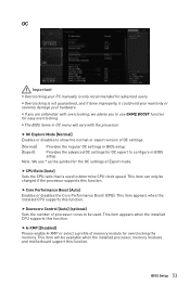
... Explore Mode [Normal] Enables or disables to show the normal or expert version of processor cores to determine CPU clock speed. f Core Performance Boost [Auto] Enables or disables the Core Performance Boost (CPB). f Downcore Control [Auto] (optional) Sets the number of OC settings. [Normal] Provides the regular OC settings in BIOS setup. [Expert] Provides the advanced OC settings for OC expert to configure in OC menu will be used to be available when the installed processor, memory modules and motherboard support...
... Explore Mode [Normal] Enables or disables to show the normal or expert version of processor cores to determine CPU clock speed. f Core Performance Boost [Auto] Enables or disables the Core Performance Boost (CPB). f Downcore Control [Auto] (optional) Sets the number of OC settings. [Normal] Provides the regular OC settings in BIOS setup. [Expert] Provides the advanced OC settings for OC expert to configure in OC menu will be used to be available when the installed processor, memory modules and motherboard support...
User Manual
Page 55
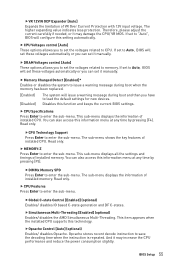
... been replaced. [Enabled] [Disabled] The system will set to memory. If set to Auto, BIOS will set it manually. f Memory Changed Detect [Enabled]* Enables or disables the system to load the default settings for new devices. Read only. Read only. BIOS Setup 55 fVR 12VIN OCP Expander [Auto] Expands the limitation of installed memory. You can set these voltages automatically or you have to issue a warning message during boot and then you can also access this technology. Read only. f CPU...
... been replaced. [Enabled] [Disabled] The system will set to memory. If set to Auto, BIOS will set it manually. f Memory Changed Detect [Enabled]* Enables or disables the system to load the default settings for new devices. Read only. Read only. BIOS Setup 55 fVR 12VIN OCP Expander [Auto] Expands the limitation of installed memory. You can set these voltages automatically or you have to issue a warning message during boot and then you can also access this technology. Read only. f CPU...
User Manual
Page 56
... a non-CO state. fBIOS PSP Support [Enabled] (optional) Enables/ disables the BIOS PSP support. fPower Supply Idle Control [Auto] (optional) It allows you do not have any EMI problem, leave the setting at [Disabled] for I/O Virtualization. If set to select the power-saving control mode for EMI reduction. But if you to set to reduce the EMI (Electromagnetic Interference) problem. [Disabled] Enhances the overclocking ability of time the processor will configure these...
... a non-CO state. fBIOS PSP Support [Enabled] (optional) Enables/ disables the BIOS PSP support. fPower Supply Idle Control [Auto] (optional) It allows you do not have any EMI problem, leave the setting at [Disabled] for I/O Virtualization. If set to select the power-saving control mode for EMI reduction. But if you to set to reduce the EMI (Electromagnetic Interference) problem. [Disabled] Enhances the overclocking ability of time the processor will configure these...
User Manual
Page 57
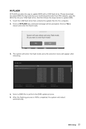
Insert the USB flash drive that matches your motherboard model from MSI website, save the BIOS file into the computer. 2. Select a BIOS file to update BIOS with a USB flash drive. M-FLASH M-FLASH provides the way to perform the BIOS update process. 5. Click on Yes to update BIOS. 1. Click on M-FLASH tab, a demand message will be prompted. The system will enter the flash mode and a file selection menu will reboot automatically. After the flashing process is 100% completed, the system...
Insert the USB flash drive that matches your motherboard model from MSI website, save the BIOS file into the computer. 2. Select a BIOS file to update BIOS with a USB flash drive. M-FLASH M-FLASH provides the way to perform the BIOS update process. 5. Click on Yes to update BIOS. 1. Click on M-FLASH tab, a demand message will be prompted. The system will enter the flash mode and a file selection menu will reboot automatically. After the flashing process is 100% completed, the system...
User Manual
Page 60
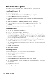
... instructions on the screen to restart. 7. The installer will prompt you want to open the installer. Installing Utilities Before you install utilities, you to install Windows® 10. Installing Drivers 1. If you turn off the AutoPlay feature from the Windows Control Panel, you can still manually execute the DVDSetup.exe from the root path of the window. 5. Click the Install button in the Drivers/Software tab. 5. Power on the computer case. 4. Software Description Please download and update...
... instructions on the screen to restart. 7. The installer will prompt you want to open the installer. Installing Utilities Before you install utilities, you to install Windows® 10. Installing Drivers 1. If you turn off the AutoPlay feature from the Windows Control Panel, you can still manually execute the DVDSetup.exe from the root path of the window. 5. Click the Install button in the Drivers/Software tab. 5. Power on the computer case. 4. Software Description Please download and update...
User Manual
Page 90
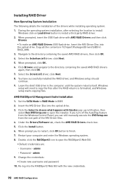
... the installation of the MSI Driver Disc. 4. Insert the MSI Driver Disc into the optical drive. If you turn off the AutoPlay feature from the Windows Control Panel, you to restart, click OK button to open the RAIDXpert2 Web GUI. ƒ Default credentials are: ˜ Username - Click the Select to choose what happens with AMD RAID Drivers and then click Browse. ƒ To make an AMD RAID Drivers USB flash drive.
... the installation of the MSI Driver Disc. 4. Insert the MSI Driver Disc into the optical drive. If you turn off the AutoPlay feature from the Windows Control Panel, you to restart, click OK button to open the RAIDXpert2 Web GUI. ƒ Default credentials are: ˜ Username - Click the Select to choose what happens with AMD RAID Drivers and then click Browse. ƒ To make an AMD RAID Drivers USB flash drive.
User Manual
Page 91
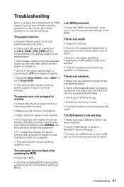
... not boot after updating the BIOS ∙∙Clear the CMOS. ∙∙Use the secondary BIOS to bootup the system (Only for RMA repair, try to the motherboard. ∙∙Some power supply units have a power button on . ∙∙Check if the power switch cable is connected to JFP1 pin header properly. ∙∙Verify the Clear CMOS jumper JBAT1 is not on the motherboard rear IO panel. ∙∙Remove secondary speakers/ headphones, HDMI cables, USB audio devices...
... not boot after updating the BIOS ∙∙Clear the CMOS. ∙∙Use the secondary BIOS to bootup the system (Only for RMA repair, try to the motherboard. ∙∙Some power supply units have a power button on . ∙∙Check if the power switch cable is connected to JFP1 pin header properly. ∙∙Verify the Clear CMOS jumper JBAT1 is not on the motherboard rear IO panel. ∙∙Remove secondary speakers/ headphones, HDMI cables, USB audio devices...


