User Manual
Page 13
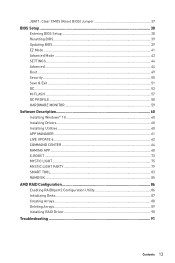
JBAT1: Clear CMOS (Reset BIOS) Jumper 37 BIOS Setup ...38 Entering BIOS Setup 38 Resetting BIOS...39 Updating BIOS...39 EZ Mode ...41 Advanced Mode ...43 SETTINGS...44 Advanced...44 Boot...49 Security ...50 Save & Exit...51 OC...53 M-FLASH ...57 OC PROFILE ...58 ...
JBAT1: Clear CMOS (Reset BIOS) Jumper 37 BIOS Setup ...38 Entering BIOS Setup 38 Resetting BIOS...39 Updating BIOS...39 EZ Mode ...41 Advanced Mode ...43 SETTINGS...44 Advanced...44 Boot...49 Security ...50 Save & Exit...51 OC...53 M-FLASH ...57 OC PROFILE ...58 ...
User Manual
Page 17
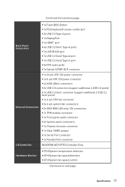
Continued from previous page Back Panel Connectors y 1x Flash BIOS Button y 1x PS/2 keyboard/ mouse combo port y 2x USB 2.0 Type-A ports y 1x DisplayPort y 1x HDMI™ port y 4x USB 3.2 Gen1 Type-A ports y 1x LAN (RJ45) ...
Continued from previous page Back Panel Connectors y 1x Flash BIOS Button y 1x PS/2 keyboard/ mouse combo port y 2x USB 2.0 Type-A ports y 1x DisplayPort y 1x HDMI™ port y 4x USB 3.2 Gen1 Type-A ports y 1x LAN (RJ45) ...
User Manual
Page 18
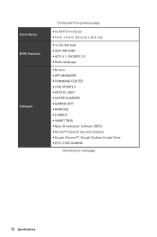
x 9.6 in . Form Factor BIOS Features Software Continued from previous page y m-ATX Form Factor y 9.6 in . (24.4 cm x 24.4 cm) y 1x 256 Mb flash y UEFI AMI BIOS y ACPI 6.1, SM BIOS 2.8 y Multi-language y Drivers y APP MANAGER y COMMAND CENTER y LIVE UPDATE 6 y MYSTIC LIGHT y SUPER CHARGER y GAMING APP y RAMDISK y X-BOOST y SMART TOOL y Open Broadcaster Software (OBS) y Norton™ Internet Security Solution y Google Chrome™, Google Toolbar, Google Drive y CPU-Z MSI GAMING Continued on next page 18 Specifications
x 9.6 in . Form Factor BIOS Features Software Continued from previous page y m-ATX Form Factor y 9.6 in . (24.4 cm x 24.4 cm) y 1x 256 Mb flash y UEFI AMI BIOS y ACPI 6.1, SM BIOS 2.8 y Multi-language y Drivers y APP MANAGER y COMMAND CENTER y LIVE UPDATE 6 y MYSTIC LIGHT y SUPER CHARGER y GAMING APP y RAMDISK y X-BOOST y SMART TOOL y Open Broadcaster Software (OBS) y Norton™ Internet Security Solution y Google Chrome™, Google Toolbar, Google Drive y CPU-Z MSI GAMING Continued on next page 18 Specifications
User Manual
Page 19
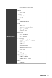
... ƒ USB with type A+C ƒ AMD Turbo USB 3.2 Gen 2 ƒ CORE Boost y VR ƒ VR Ready y Gamer Experience ƒ GAMING HOTKEY ƒ GAMING MOUSE Control y BIOS ƒ Click BIOS 5 Specifications 19
... ƒ USB with type A+C ƒ AMD Turbo USB 3.2 Gen 2 ƒ CORE Boost y VR ƒ VR Ready y Gamer Experience ƒ GAMING HOTKEY ƒ GAMING MOUSE Control y BIOS ƒ Click BIOS 5 Specifications 19
User Manual
Page 22
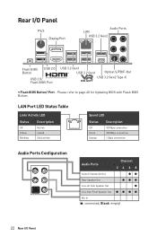
... Speaker Out ● Line-Out/ Front Speaker Out Mic In (●: connected, Blank: empty) 22 Rear I /O Panel PS/2 DisplayPort Audio Ports LAN USB 3.2 Gen2 Flash BIOS Button USB 2.0 USB 2.0/ Flash BIOS Port USB 3.2 Gen1 USB 3.2 Gen1 Optical S/PDIF-Out USB 3.2 Gen2 Type-C y Flash...
... Speaker Out ● Line-Out/ Front Speaker Out Mic In (●: connected, Blank: empty) 22 Rear I /O Panel PS/2 DisplayPort Audio Ports LAN USB 3.2 Gen2 Flash BIOS Button USB 2.0 USB 2.0/ Flash BIOS Port USB 3.2 Gen1 USB 3.2 Gen1 Optical S/PDIF-Out USB 3.2 Gen2 Type-C y Flash...
User Manual
Page 26
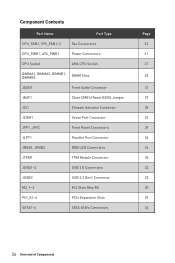
...~3 Fan Connectors CPU_PWR1, ATX_PWR1 Power Connectors CPU Socket AM4 CPU Socket DIMMA1, DIMMA2, DIMMB1, DIMMB2 DIMM Slots JAUD1 Front Audio Connector JBAT1 Clear CMOS (Reset BIOS) Jumper JCI1 Chassis Intrusion Connector JCOM1 Serial Port Connector JFP1, JFP2 Front Panel Connectors JLPT1 Parallel Port Connector JRGB1, JRGB2 RGB LED Connectors JTPM1 TPM...
...~3 Fan Connectors CPU_PWR1, ATX_PWR1 Power Connectors CPU Socket AM4 CPU Socket DIMMA1, DIMMA2, DIMMB1, DIMMB2 DIMM Slots JAUD1 Front Audio Connector JBAT1 Clear CMOS (Reset BIOS) Jumper JCI1 Chassis Intrusion Connector JCOM1 Serial Port Connector JFP1, JFP2 Front Panel Connectors JLPT1 Parallel Port Connector JRGB1, JRGB2 RGB LED Connectors JTPM1 TPM...
User Manual
Page 27
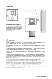
...cooling fans work properly to protect the CPU from overheating. Important y When changing the processor, the system configuration could be cleared and reset BIOS to default values, due to install a CPU heatsink. A CPU heatsink is designed to prevent overheating and maintain system stability. y This ...lining up the CPU for more details about installation. y Always unplug the power cord from the power outlet before booting your system. MSI® does not guarantee the damages or risks caused by inadequate operation beyond product specifications is the Pin 1 indicator. Any attempt ...
...cooling fans work properly to protect the CPU from overheating. Important y When changing the processor, the system configuration could be cleared and reset BIOS to default values, due to install a CPU heatsink. A CPU heatsink is designed to prevent overheating and maintain system stability. y This ...lining up the CPU for more details about installation. y Always unplug the power cord from the power outlet before booting your system. MSI® does not guarantee the damages or risks caused by inadequate operation beyond product specifications is the Pin 1 indicator. Any attempt ...
User Manual
Page 28
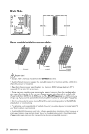
...module installation recommendation DIMMB2 DIMMA2 DIMMB2 DIMMA2 DIMMB2 DIMMB1 DIMMA2 DIMMA1 Important y Always insert memory modules in the DIMMA2 slot first. Go to BIOS and find the DRAM Frequency to set the memory frequency if you want to operate the memory at the marked or at a lower ... may operate at a higher frequency. y It is suggested to use a more information on its Serial Presence Detect (SPD). Please refer www.msi.com for more efficient memory cooling system for full DIMMs installation or overclocking. y Some memory modules may operate lower than the amount of installed...
...module installation recommendation DIMMB2 DIMMA2 DIMMB2 DIMMA2 DIMMB2 DIMMB1 DIMMA2 DIMMA1 Important y Always insert memory modules in the DIMMA2 slot first. Go to BIOS and find the DRAM Frequency to set the memory frequency if you want to operate the memory at the marked or at a lower ... may operate at a higher frequency. y It is suggested to use a more information on its Serial Presence Detect (SPD). Please refer www.msi.com for more efficient memory cooling system for full DIMMs installation or overclocking. y Some memory modules may operate lower than the amount of installed...
User Manual
Page 33
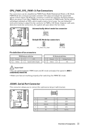
... the fan connector to PWM or DC Mode. JCOM1: Serial Port Connector This connector allows you plug a 3-pin (Non-PWM) fan to a fan connector in BIOS > HARDWARE MONITOR.
... the fan connector to PWM or DC Mode. JCOM1: Serial Port Connector This connector allows you plug a 3-pin (Non-PWM) fan to a fan connector in BIOS > HARDWARE MONITOR.
User Manual
Page 35
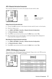
Go to Enabled. 5. Set Chassis Intrusion to BIOS > SETTINGS > Security > Chassis Intrusion Configuration. 4. Set Chassis Intrusion to select Yes. Press F10 to save and exit and then press the Enter key to connect ... pin2 10 No Pin 11 LPC address & data pin3 12 Ground 13 LPC Frame 14 Ground Overview of Components 35 Connect the JCI1 connector to BIOS > SETTINGS > Security > Chassis Intrusion Configuration. 2. Normal (default) Trigger the chassis intrusion event Using chassis intrusion detector 1. Go to the chassis intrusion switch/ sensor on...
Go to Enabled. 5. Set Chassis Intrusion to BIOS > SETTINGS > Security > Chassis Intrusion Configuration. 4. Set Chassis Intrusion to select Yes. Press F10 to save and exit and then press the Enter key to connect ... pin2 10 No Pin 11 LPC address & data pin3 12 Ground 13 LPC Frame 14 Ground Overview of Components 35 Connect the JCI1 connector to BIOS > SETTINGS > Security > Chassis Intrusion Configuration. 2. Normal (default) Trigger the chassis intrusion event Using chassis intrusion detector 1. Go to the chassis intrusion switch/ sensor on...
User Manual
Page 37
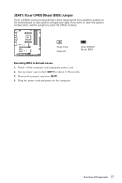
Use a jumper cap to default values 1. Overview of Components 37 Keep Data (default) Clear CMOS/ Reset BIOS Resetting BIOS to short JBAT1 for about 5-10 seconds. 3. JBAT1: Clear CMOS (Reset BIOS) Jumper There is CMOS memory onboard that is external powered from JBAT1. 4. Remove the jumper cap from a battery located on the computer. Power off the computer and unplug the power cord 2. Plug the power cord and power on the motherboard to clear the CMOS memory. If you want to clear the system configuration, set the jumpers to save system configuration data.
Use a jumper cap to default values 1. Overview of Components 37 Keep Data (default) Clear CMOS/ Reset BIOS Resetting BIOS to short JBAT1 for about 5-10 seconds. 3. JBAT1: Clear CMOS (Reset BIOS) Jumper There is CMOS memory onboard that is external powered from JBAT1. 4. Remove the jumper cap from a battery located on the computer. Power off the computer and unplug the power cord 2. Plug the power cord and power on the motherboard to clear the CMOS memory. If you want to clear the system configuration, set the jumpers to save system configuration data.
User Manual
Page 38
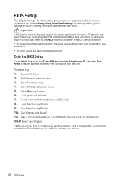
... Profile F10: Save Change and Reset* F12: Take a screenshot and save it provides the modification information. BIOS Setup The default settings offer the optimal performance for BIOS item description. y The pictures in this chapter are for reference only and may be for better system performance... and it to the HELP information panel for system stability in normal conditions. Therefore, the description may vary from the latest BIOS and should always keep the default settings to avoid possible system damage or failure booting unless you are continuously update for reference only...
... Profile F10: Save Change and Reset* F12: Take a screenshot and save it provides the modification information. BIOS Setup The default settings offer the optimal performance for BIOS item description. y The pictures in this chapter are for reference only and may be for better system performance... and it to the HELP information panel for system stability in normal conditions. Therefore, the description may vary from the latest BIOS and should always keep the default settings to avoid possible system damage or failure booting unless you are continuously update for reference only...
User Manual
Page 39
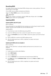
... your motherboard model from MSI website. Click on Yes to reboot the system and enter the flash mode. 4. Select a BIOS file to start updating BIOS. 6. Click on the motherboard. And then click Next and Start to perform the BIOS update process. 5. Updating BIOS Updating BIOS with Live Update 6 Before...USB flash drive. Install and launch MSI LIVE UPDATE 6. 2. Click Next and choose In Windows mode. Resetting BIOS You might need to restore the default BIOS setting to solve certain problems. There are several ways to reset BIOS: y Go to BIOS and press F6 to download and install...
... your motherboard model from MSI website. Click on Yes to reboot the system and enter the flash mode. 4. Select a BIOS file to start updating BIOS. 6. Click on the motherboard. And then click Next and Start to perform the BIOS update process. 5. Updating BIOS Updating BIOS with Live Update 6 Before...USB flash drive. Install and launch MSI LIVE UPDATE 6. 2. Click Next and choose In Windows mode. Resetting BIOS You might need to restore the default BIOS setting to solve certain problems. There are several ways to reset BIOS: y Go to BIOS and press F6 to download and install...
User Manual
Page 40
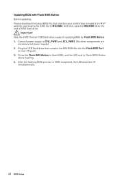
...supply to the root of USB flash drive. Press the Flash BIOS Button to flash BIOS, and the LED next to MSI.ROM. After the flashing BIOS process is 100% completed, the LED would be off simultaneously. 40 BIOS Setup Plug the USB flash drive that matches your motherboard model... from MSI® website and rename the BIOS file to Flash BIOS Button starts flashing. 4. Updating BIOS with Flash BIOS Button Before updating: Please download the latest BIOS file that contains the MSI.ROM file into the Flash BIOS Port on rear I/O panel. 3. Important ...
...supply to the root of USB flash drive. Press the Flash BIOS Button to flash BIOS, and the LED next to MSI.ROM. After the flashing BIOS process is 100% completed, the LED would be off simultaneously. 40 BIOS Setup Plug the USB flash drive that matches your motherboard model... from MSI® website and rename the BIOS file to Flash BIOS Button starts flashing. 4. Updating BIOS with Flash BIOS Button Before updating: Please download the latest BIOS file that contains the MSI.ROM file into the Flash BIOS Port on rear I/O panel. 3. Important ...
User Manual
Page 41
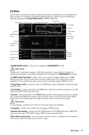
...take a screenshot and save it to USB flash drive (FAT/ FAT32 format only). y A-XMP switch (optional) - allows you to find the item listing. BIOS Setup 41 Important In search page, only the F6, F10 and F12 function keys are available. y Language - y Screenshot - click on it to toggle the...left to configure the basic setting. shows the CPU/ DDR speed, CPU/ MB temperature, MB/ CPU type, memory size, CPU/ DDR voltage, BIOS version and build date. EZ Mode At EZ mode, it provides the basic system information and allows you to right. A-XMP switch Setup Mode switch...
...take a screenshot and save it to USB flash drive (FAT/ FAT32 format only). y A-XMP switch (optional) - allows you to find the item listing. BIOS Setup 41 Important In search page, only the F6, F10 and F12 function keys are available. y Language - y Screenshot - click on it to toggle the...left to configure the basic setting. shows the CPU/ DDR speed, CPU/ MB temperature, MB/ CPU type, memory size, CPU/ DDR voltage, BIOS version and build date. EZ Mode At EZ mode, it provides the basic system information and allows you to right. A-XMP switch Setup Mode switch...
User Manual
Page 42
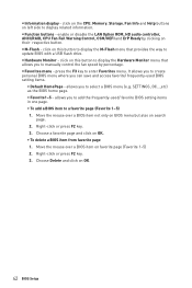
... related information. Right-click or press F2 key. 3. Choose Delete and click on favorite page (Favorite 1~5) 2. allows you to add the frequently-used BIOS setting items. ƒ Default HomePage - Right-click or press F2 key. 3. enable or disable the LAN Option ROM, HD audio controller, AHCI/RAID..., CPU Fan Fail Warning Control, CSM/UEFI and ErP Ready by percentage. click on left side to update BIOS with a USB flash drive. Choose a favorite page and click on their respective button. It allows you can save and access favorite/ frequently-used...
... related information. Right-click or press F2 key. 3. Choose Delete and click on favorite page (Favorite 1~5) 2. allows you to add the frequently-used BIOS setting items. ƒ Default HomePage - Right-click or press F2 key. 3. enable or disable the LAN Option ROM, HD audio controller, AHCI/RAID..., CPU Fan Fail Warning Control, CSM/UEFI and ErP Ready by percentage. click on left side to update BIOS with a USB flash drive. Choose a favorite page and click on their respective button. It allows you can save and access favorite/ frequently-used...
User Manual
Page 43
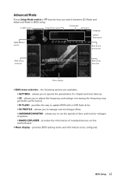
...information GAME BOOST switch Boot device priority bar BIOS menu selection BIOS menu selection Menu display y BIOS menu selection - the following options are available: ƒ SETTINGS - y Menu display - provides BIOS setting items and information to update BIOS with a USB flash drive. ƒ OC... PROFILE - provides the way to be configured. BIOS Setup 43 allows you to manage overclocking profiles. ƒ HARDWARE MONITOR ...
...information GAME BOOST switch Boot device priority bar BIOS menu selection BIOS menu selection Menu display y BIOS menu selection - the following options are available: ƒ SETTINGS - y Menu display - provides BIOS setting items and information to update BIOS with a USB flash drive. ƒ OC... PROFILE - provides the way to be configured. BIOS Setup 43 allows you to manage overclocking profiles. ƒ HARDWARE MONITOR ...
User Manual
Page 44
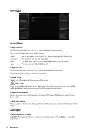
...power cable connections of the device and motherboard. Use tab key to switch between time elements. The month from 1 to Sat, determined by BIOS. through Dec. The year can be adjusted by numeric function keys. f SATA PortX Shows the information of the week, from Sun to ...protocol and latency timer. f System Time Sets the system time. The date from Jan. Use tab key to enter the sub-menu. 44 BIOS Setup Important If the connected SATA device is . Press Enter to switch between date elements. f DMI Information Shows system information, desktop Board ...
...power cable connections of the device and motherboard. Use tab key to switch between time elements. The month from 1 to Sat, determined by BIOS. through Dec. The year can be adjusted by numeric function keys. f SATA PortX Shows the information of the week, from Sun to ...protocol and latency timer. f System Time Sets the system time. The date from Jan. Use tab key to enter the sub-menu. 44 BIOS Setup Important If the connected SATA device is . Press Enter to switch between date elements. f DMI Information Shows system information, desktop Board ...
User Manual
Page 45
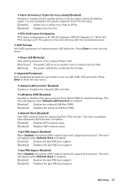
... Ipv6 protocol. Press Enter to enter the sub-menu. fNetwork Stack [Disabled] Sets UEFI network stack for detailed settings. BIOS Setup 45 This item is available when Onboard LAN Controller is for MSI M.2 Xpander / MSI M.2 Xpander-Z / Other M.2 PCIe storage card. This item will appear when Onboard LAN Controller is enabled. [Enabled] Enables the...
... Ipv6 protocol. Press Enter to enter the sub-menu. fNetwork Stack [Disabled] Sets UEFI network stack for detailed settings. BIOS Setup 45 This item is available when Onboard LAN Controller is for MSI M.2 Xpander / MSI M.2 Xpander-Z / Other M.2 PCIe storage card. This item will appear when Onboard LAN Controller is enabled. [Enabled] Enables the...
User Manual
Page 46
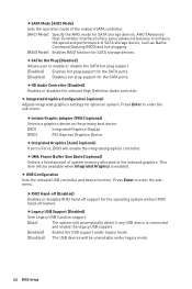
... USB support. [Enabled] Enable the USB support under legacy mode. [Disabled] The USB devices will be unavailable under legacy mode. 46 BIOS Setup Press Enter to enhance the speed and performance of SATA storage device, such as the primary boot device. [IGD] Integrated Graphics Display...system without XHCI hand-off feature. fUMA Frame Buffer Size [Auto] (optional) Selects a fixed amount of system memory allocated to Force, BIOS will automatically detect if any USB device is enabled. fHD Audio Controller [Enabled] Enables or disables the onboard High Definition Audio...
... USB support. [Enabled] Enable the USB support under legacy mode. [Disabled] The USB devices will be unavailable under legacy mode. 46 BIOS Setup Press Enter to enhance the speed and performance of SATA storage device, such as the primary boot device. [IGD] Integrated Graphics Display...system without XHCI hand-off feature. fUMA Frame Buffer Size [Auto] (optional) Selects a fixed amount of system memory allocated to Force, BIOS will automatically detect if any USB device is enabled. fHD Audio Controller [Enabled] Enables or disables the onboard High Definition Audio...


