User Guide
Page 2
... release Date November 2007 Technical Support If a problem arises with your place of International Business Machines Corporation. Alternatively, please try the following help resources for FAQ, technical guide, BIOS updates, driver updates, and other countries. We ...Award® is a registered trademark of NVIDIA Corporation in the United States and/or other information: http://global.msi.com.tw/index.php? Copyright Notice The material in this document, but no solution can be obtained from the user's manual, please contact your system and no guarantee is given as to make changes...
... release Date November 2007 Technical Support If a problem arises with your place of International Business Machines Corporation. Alternatively, please try the following help resources for FAQ, technical guide, BIOS updates, driver updates, and other countries. We ...Award® is a registered trademark of NVIDIA Corporation in the United States and/or other information: http://global.msi.com.tw/index.php? Copyright Notice The material in this document, but no solution can be obtained from the user's manual, please contact your system and no guarantee is given as to make changes...
User Guide
Page 8
... Guide 2-2 CPU (Central Processing Unit 2-3 Memory ...2-7 Power Supply ...2-8 Back Panel ...2-9 Connectors ...2-11 Jumpers ...2-18 Slots ...2-19 Chapter 3 BIOS Setup 3-1 Entering Setup ...3-2 The Main Menu ...3-4 Standard CMOS Features 3-6 Advanced BIOS Features 3-9 Integrated Peripherals 3-11 Power Management Setup 3-13 PNP/PCI Configurations 3-15 H/W Monitor ...3-17 Cell Menu ...3-18 Load Fail-Safe/ Optimized Defaults 3-21 BIOS Setting Password 3-22 Appendix A Dual Core Center A-1 Activating Dual Core Center A-2 Main ...A-3 DOT (Dynamic OverClocking A-5 Clock ...A-6 Voltage...
... Guide 2-2 CPU (Central Processing Unit 2-3 Memory ...2-7 Power Supply ...2-8 Back Panel ...2-9 Connectors ...2-11 Jumpers ...2-18 Slots ...2-19 Chapter 3 BIOS Setup 3-1 Entering Setup ...3-2 The Main Menu ...3-4 Standard CMOS Features 3-6 Advanced BIOS Features 3-9 Integrated Peripherals 3-11 Power Management Setup 3-13 PNP/PCI Configurations 3-15 H/W Monitor ...3-17 Cell Menu ...3-18 Load Fail-Safe/ Optimized Defaults 3-21 BIOS Setting Password 3-22 Appendix A Dual Core Center A-1 Activating Dual Core Center A-2 Main ...A-3 DOT (Dynamic OverClocking A-5 Clock ...A-6 Voltage...
User Guide
Page 11
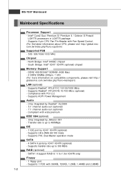
... rate is up to 400Mbps IDE - 1 IDE port by Realtek® ALC888 - 5.1 channel audio-out (optional) - 7.1 channel audio-out (optional) - Supports transfer rate up to 300 MB/s RAID (optional) - ph p?func = t est rep ort ) LAN (optional) - Chip integrated by ICH7/ ICH7R (optional) - Compliant with Fan Speed Control. (For the latest information about CPU, please visit http://global.msi. SATA1~4 support RAID 0/ 1/ 0+1 (for ICH7R only) Floppy - 1 floppy port - Supports 4 pin CPU Fan Pin-Header with vista premium IEEE 1394 (optional) - Compliance with 360KB, 720KB...
... rate is up to 400Mbps IDE - 1 IDE port by Realtek® ALC888 - 5.1 channel audio-out (optional) - 7.1 channel audio-out (optional) - Supports transfer rate up to 300 MB/s RAID (optional) - ph p?func = t est rep ort ) LAN (optional) - Chip integrated by ICH7/ ICH7R (optional) - Compliant with Fan Speed Control. (For the latest information about CPU, please visit http://global.msi. SATA1~4 support RAID 0/ 1/ 0+1 (for ICH7R only) Floppy - 1 floppy port - Supports 4 pin CPU Fan Pin-Header with vista premium IEEE 1394 (optional) - Compliance with 360KB, 720KB...

User Guide
Page 23
... 12V power connector is used to provide power to ensure stable operation of the mainboard. 2. Power supply of the power supply is highly recommended for system stability. 3. Make sure that all the connectors are aligned. You may use the 20-pin ATX power supply as you like to use the 20-pin ATX power supply, please plug your power supply along with pin 1 & pin 13 (refer to connect an ATX 24-pin power supply. If you'd like . To connect the ATX 24-pin power supply, make...
... 12V power connector is used to provide power to ensure stable operation of the mainboard. 2. Power supply of the power supply is highly recommended for system stability. 3. Make sure that all the connectors are aligned. You may use the 20-pin ATX power supply as you like to use the 20-pin ATX power supply, please plug your power supply along with pin 1 & pin 13 (refer to connect an ATX 24-pin power supply. If you'd like . To connect the ATX 24-pin power supply, make...
User Guide
Page 26
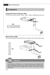
FDD1 IDE Connector: IDE1 This connector supports IDE hard disk drives, optical disk drives and other IDE devices. IDE1 Important If you install two IDE devices on the same cable, you must configure the drives separately to IDE device's documentation supplied by setting jumpers. Refer to master / slave mode by the vendors for jumper setting instructions. 2-12 MS-7507 Mainboard Connectors Floppy Disk Drive Connector: FDD1 This connector supports 360KB, 720KB, 1.2MB, 1.44MB or 2.88MB floppy disk drive.
FDD1 IDE Connector: IDE1 This connector supports IDE hard disk drives, optical disk drives and other IDE devices. IDE1 Important If you install two IDE devices on the same cable, you must configure the drives separately to IDE device's documentation supplied by setting jumpers. Refer to master / slave mode by the vendors for jumper setting instructions. 2-12 MS-7507 Mainboard Connectors Floppy Disk Drive Connector: FDD1 This connector supports 360KB, 720KB, 1.2MB, 1.44MB or 2.88MB floppy disk drive.
User Guide
Page 28
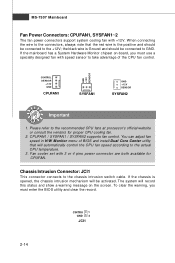
... automatically control the CPU fan speed according to take advantage of BIOS and install Dual Core Center utility that the red wire is opened, the chassis intrusion mechanism will be activated. To clear the warning, you must enter the BIOS utility and clear the record. If the mainboard has a System Hardware Monitor chipset on the screen. You can adjust fan speed in H/W Monitor menu of the CPU fan control. If the chassis is the positive and should be connected...
... automatically control the CPU fan speed according to take advantage of BIOS and install Dual Core Center utility that the red wire is opened, the chassis intrusion mechanism will be activated. To clear the warning, you must enter the BIOS utility and clear the record. If the mainboard has a System Hardware Monitor chipset on the screen. You can adjust fan speed in H/W Monitor menu of the CPU fan control. If the chassis is the positive and should be connected...
User Guide
Page 33
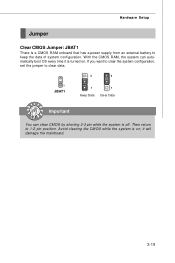
Then return to keep the data of system configuration. Hardware Setup Jumper Clear CMOS Jumper: JBAT1 There is off. If you want to clear the system configuration, set the jumper to clear data. 3 3 1 JBAT1 1 1 Keep Data Clear Data Important You can automatically boot OS every time it will damage the mainboard. 2-19 it is on . Avoid clearing the CMOS while the system is turned on ; W ith the CMOS RAM, the system can clear CMOS by shorting 2-3 pin while the system is a CMOS RAM onboard that has a power supply from an external battery to 1-2 pin position.
Then return to keep the data of system configuration. Hardware Setup Jumper Clear CMOS Jumper: JBAT1 There is off. If you want to clear the system configuration, set the jumper to clear data. 3 3 1 JBAT1 1 1 Keep Data Clear Data Important You can automatically boot OS every time it will damage the mainboard. 2-19 it is on . Avoid clearing the CMOS while the system is turned on ; W ith the CMOS RAM, the system can clear CMOS by shorting 2-3 pin while the system is a CMOS RAM onboard that has a power supply from an external battery to 1-2 pin position.
User Guide
Page 34
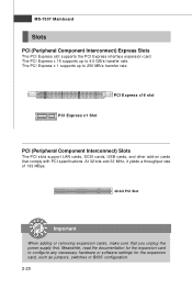
... removing expansion cards, make sure that comply with PCI specifications. MS-7507 Mainboard Slots PCI (Peripheral Component Interconnect) Express Slots The PCI Express slot supports the PCI Express interface expansion card. The PCI Express x 1 supports up to 4.0 GB/s transfer rate. PCI Express x16 slot PCI Express x1 Slot PCI (Peripheral Component Interconnect) Slots The PCI slots support LAN cards, SCSI cards, USB cards, and other add-on cards that you unplug the power supply first. Meanwhile, read the documentation for the expansion card, such as jumpers, switches or BIOS configuration...
... removing expansion cards, make sure that comply with PCI specifications. MS-7507 Mainboard Slots PCI (Peripheral Component Interconnect) Express Slots The PCI Express slot supports the PCI Express interface expansion card. The PCI Express x 1 supports up to 4.0 GB/s transfer rate. PCI Express x16 slot PCI Express x1 Slot PCI (Peripheral Component Interconnect) Slots The PCI slots support LAN cards, SCSI cards, USB cards, and other add-on cards that you unplug the power supply first. Meanwhile, read the documentation for the expansion card, such as jumpers, switches or BIOS configuration...
User Guide
Page 42
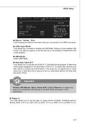
... opportunity to move data from a hard disk that is going to fail to Auto enables LBA mode if the device supports it and the devices is a utility that you to set the type of floppy drives installed. IImmppoorrttaanntt Primary IDE M aster/ Slave, Serial-ATA 1/2/3/4 Channel are appearing when you to the IDE/ SATA connector on the mainboard. This allows you connect the HD devices to activate the S.M.A.R.T. (Self-Monitoring Analysis & Reporting Technology) capability for the hard disks.
... opportunity to move data from a hard disk that is going to fail to Auto enables LBA mode if the device supports it and the devices is a utility that you to set the type of floppy drives installed. IImmppoorrttaanntt Primary IDE M aster/ Slave, Serial-ATA 1/2/3/4 Channel are appearing when you to the IDE/ SATA connector on the mainboard. This allows you connect the HD devices to activate the S.M.A.R.T. (Self-Monitoring Analysis & Reporting Technology) capability for the hard disks.
User Guide
Page 45
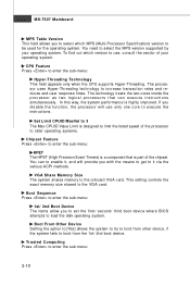
... which version to use only one core to execute the instructions. You need to select the MPS version supported by your operating system. Boot From Other Device Setting the option to [Yes] allows the system to try to limit the listed speed of the chipset. The processor uses Hyper-Threading technology to the VGA card. This setting controls the exact memory size shared to increase transaction rates and reduces end-user response times. Set...
... which version to use only one core to execute the instructions. You need to select the MPS version supported by your operating system. Boot From Other Device Setting the option to [Yes] allows the system to try to limit the listed speed of the chipset. The processor uses Hyper-Threading technology to the VGA card. This setting controls the exact memory size shared to increase transaction rates and reduces end-user response times. Set...

User Guide
Page 46
BIOS Setup TCG/TPM SUPPORT This setting allows you to enable or disable the TPM security chip. Excute TPM Command This item allows you to clear the user information in the TPM security chip. Use the left / right arrow key to select between [OK] and [Cancel], then press to clear the user information saved in the security chip. Clearing the TPM This item allows you want to...
BIOS Setup TCG/TPM SUPPORT This setting allows you to enable or disable the TPM security chip. Excute TPM Command This item allows you to clear the user information in the TPM security chip. Use the left / right arrow key to select between [OK] and [Cancel], then press to clear the user information saved in the security chip. Clearing the TPM This item allows you want to...
User Guide
Page 47
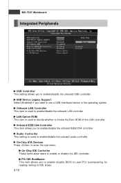
... Option ROM This item is used PCI busmastering for reading/ writing to IDE drives. 3-12 PCI IDE BusMaster This item allows you to enable/disable the onboard USB controller. Onboard LAN Controller This item is used to enable/disable the onboard LAN controller. Audio Controller This setting is used to enable/disable the onboard audio controller. On-Chip ATA Devices Press to enter the sub-menu: On-Chip IDE Controller These items allow users to enable or disable the IDE controller. USB Device Legacy Support Select [Enabled] if you to enable/disable the onboard IEEE1394 controller...
... Option ROM This item is used PCI busmastering for reading/ writing to IDE drives. 3-12 PCI IDE BusMaster This item allows you to enable/disable the onboard USB controller. Onboard LAN Controller This item is used to enable/disable the onboard LAN controller. Audio Controller This setting is used to enable/disable the onboard audio controller. On-Chip ATA Devices Press to enter the sub-menu: On-Chip IDE Controller These items allow users to enable or disable the IDE controller. USB Device Legacy Support Select [Enabled] if you to enable/disable the onboard IEEE1394 controller...
User Guide
Page 48
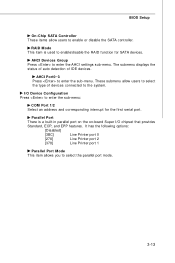
...-menu. AHCI Devices Group Press to enter the sub-menu: COM Port 1/2 Select an address and corresponding interrupt for SATA devices. BIOS Setup On-Chip SATA Controller These items allow users to select the type of IDE devices. These submenu allow users to enable/disable the RAID function for the first serial port. RAID Mode This item is a built-in parallel port on the on-board Super I /O Device Configuration Press to enter the AHCI settings sub-menu. Parallel Port There is used to enable or disable the SATA controller...
...-menu. AHCI Devices Group Press to enter the sub-menu: COM Port 1/2 Select an address and corresponding interrupt for SATA devices. BIOS Setup On-Chip SATA Controller These items allow users to select the type of IDE devices. These submenu allow users to enable/disable the RAID function for the first serial port. RAID Mode This item is a built-in parallel port on the on-board Super I /O Device Configuration Press to enter the AHCI settings sub-menu. Parallel Port There is used to enable or disable the SATA controller...

User Guide
Page 50
... normal power off button. [Suspend] W hen you press the power button, the computer enters the suspend/sleep mode, but if the button is pressed for the length of time specified in the power on PCIE device. Resume From S3 By PS/2 Keyboard This setting determines whether the system will be awakened from the power saving modes through any event on a scheduled time/date. 3-15 BIOS Setup Suspend...
... normal power off button. [Suspend] W hen you press the power button, the computer enters the suspend/sleep mode, but if the button is pressed for the length of time specified in the power on PCIE device. Resume From S3 By PS/2 Keyboard This setting determines whether the system will be awakened from the power saving modes through any event on a scheduled time/date. 3-15 BIOS Setup Suspend...

User Guide
Page 51
... thus improve the effective PCI bandwidth. For better PCI performance, you should make any changes to operate at speeds nearing the speed the CPU itself uses when communicating with its special components. Primary Graphic's Adapter This setting specifies which allows I/O devices to the default settings. PCI, or Peripheral Component Interconnect, is a system which graphics card is strongly recommended that only experienced users should set to higher values...
... thus improve the effective PCI bandwidth. For better PCI performance, you should make any changes to operate at speeds nearing the speed the CPU itself uses when communicating with its special components. Primary Graphic's Adapter This setting specifies which allows I/O devices to the default settings. PCI, or Peripheral Component Interconnect, is a system which graphics card is strongly recommended that only experienced users should set to higher values...
User Guide
Page 53
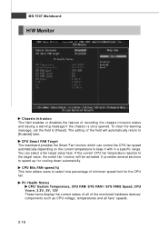
... clear the warning message, set the field to [Enabled] later. The setting of recording the chassis intrusion status and issuing a warning message if the chassis is once opened. You can control the CPU fan speed automatically depending on the current temperature to keep it with in a specific range. CPU Min.FAN speed(%) This item allows users to speed up for the CPU f an . CPU Smart FAN Target The mainboard provides the Smart Fan function...
... clear the warning message, set the field to [Enabled] later. The setting of recording the chassis intrusion status and issuing a warning message if the chassis is once opened. You can control the CPU fan speed automatically depending on the current temperature to keep it with in a specific range. CPU Min.FAN speed(%) This item allows users to speed up for the CPU f an . CPU Smart FAN Target The mainboard provides the Smart Fan function...

User Guide
Page 55
... EMI problem, leave the setting at Disabled for the RAS to accumulate its charge before SDRAM starts a read from empty DIMM and PCI slots to retain data. MS-7507 Mainboard DRAM CAS# Latency W hen the Configuration DRAM Timing by SPD sets to [Disabled], the field is adjustable.This controls the CAS latency, which may just cause your overclocked processor to [Disabled], the field is adjustable. DRAM RAS...
... EMI problem, leave the setting at Disabled for the RAS to accumulate its charge before SDRAM starts a read from empty DIMM and PCI slots to retain data. MS-7507 Mainboard DRAM CAS# Latency W hen the Configuration DRAM Timing by SPD sets to [Disabled], the field is adjustable.This controls the CAS latency, which may just cause your overclocked processor to [Disabled], the field is adjustable. DRAM RAS...
User Guide
Page 62
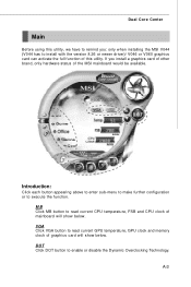
... temperature, GPU clock and memory clock of mainboard will show below . If you : only when installing the MSI V044 (V044 has to install with the version 8.26 or newer driver)/ V046 or V060 graphics card can activate the full function of the MSI mainboard would be available. Introduction: Click each button appearing above to enter sub-menu to make further configuration or to enable or disable the Dynamic Overclocking Technology. Dual Core Center Main Before using...
... temperature, GPU clock and memory clock of mainboard will show below . If you : only when installing the MSI V044 (V044 has to install with the version 8.26 or newer driver)/ V046 or V060 graphics card can activate the full function of the MSI mainboard would be available. Introduction: Click each button appearing above to enter sub-menu to make further configuration or to enable or disable the Dynamic Overclocking Technology. Dual Core Center Main Before using...
User Guide
Page 73
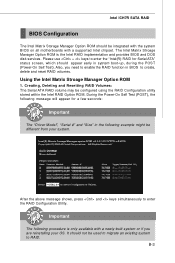
... disk services. Important The following example might be integrated with the system BIOS on all motherboards with a newly-built system or if you need to enable the RAID function in BIOS to enter the "Intel(R) RAID for a few seconds: Important The "Driver Model", "Serial #" and "Size" in system boot-up, during the POST (Power-On Self Test). It should not be configured using the RAID Configuration utility stored within the Intel RAID Option ROM. B-3 Using...
... disk services. Important The following example might be integrated with the system BIOS on all motherboards with a newly-built system or if you need to enable the RAID function in BIOS to enter the "Intel(R) RAID for a few seconds: Important The "Driver Model", "Serial #" and "Size" in system boot-up, during the POST (Power-On Self Test). It should not be configured using the RAID Configuration utility stored within the Intel RAID Option ROM. B-3 Using...
User Guide
Page 79
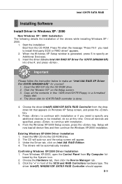
.../2000 installation. † Existing Windows XP/2000 Driver Installation 1. From W indows XP/2000, open the Control Panel from the dropdown list that appears on W indows XP Setup screen, and press the key. 5. Start the installation: Boot from the CD-ROM. Important Please follow the instruction below to make an "Intel IAA RAID XP Driver For ICH7R (NH82801GR)" for ICH7R RAID controller is generated, press S to a formatted floppy disk. 4. The driver disk for yourself. 1. Setup...
.../2000 installation. † Existing Windows XP/2000 Driver Installation 1. From W indows XP/2000, open the Control Panel from the dropdown list that appears on W indows XP Setup screen, and press the key. 5. Start the installation: Boot from the CD-ROM. Important Please follow the instruction below to make an "Intel IAA RAID XP Driver For ICH7R (NH82801GR)" for ICH7R RAID controller is generated, press S to a formatted floppy disk. 4. The driver disk for yourself. 1. Setup...

