User Guide
Page 1
...cables and A.C. Micro-Star International MS-7101 This device complies with the emission limits. Notice 1 The changes or modifications not expressly approved by the party responsible for a class B digital device, pursuant to part 15 of the FCC rules. Operation of the FCC Rules. FCC-B Radio Frequency... comply with the instruction manual, may cause harmful interference to radio communications. These limits are designed to operate the equipment. This equipment generates, uses and can radiate radio frequency energy and, if not installed and used in order to comply with Part 15 of this...
...cables and A.C. Micro-Star International MS-7101 This device complies with the emission limits. Notice 1 The changes or modifications not expressly approved by the party responsible for a class B digital device, pursuant to part 15 of the FCC rules. Operation of the FCC Rules. FCC-B Radio Frequency... comply with the instruction manual, may cause harmful interference to radio communications. These limits are designed to operate the equipment. This equipment generates, uses and can radiate radio frequency energy and, if not installed and used in order to comply with Part 15 of this...
User Guide
Page 3
... in an environment unconditioned, storage temperature above 60° C (140°F), it . All cautions and warnings on a reliable flat surface before setting it work well or you can not step on card or module. 9. Always read the safety instructions carefully. 2. Do not cover the openings. 6. Make sure the voltage of breakage. 12. Place the power cord such a way...
... in an environment unconditioned, storage temperature above 60° C (140°F), it . All cautions and warnings on a reliable flat surface before setting it work well or you can not step on card or module. 9. Always read the safety instructions carefully. 2. Do not cover the openings. 6. Make sure the voltage of breakage. 12. Place the power cord such a way...
User Guide
Page 6
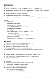
...) sequence processor or higher speed. Supports DDR 266/333/400 memory interface. - Hi-Speed USB (USB2.0) controller, 480Mb/sec, 8 ports. - 2 Serial ATA/150 ports. - 2 channel Ultra ATA 66/100 bus Master IDE controller. - z Supports dual channel DDR266/333/400 MHz. (For the updated supporting memory modules, please visit http://www.msi.com.tw/program/products/mainboard/mbd/pro_mbd_trp_list.php ) Slots z One AGR (Advance Graphics Riser) slot for compatible AGP VGA cards. z Two PCI 2.3 32-bit PCI bus slots (support 3.3v/5v PCI bus interface). Can connect up...
...) sequence processor or higher speed. Supports DDR 266/333/400 memory interface. - Hi-Speed USB (USB2.0) controller, 480Mb/sec, 8 ports. - 2 Serial ATA/150 ports. - 2 channel Ultra ATA 66/100 bus Master IDE controller. - z Supports dual channel DDR266/333/400 MHz. (For the updated supporting memory modules, please visit http://www.msi.com.tw/program/products/mainboard/mbd/pro_mbd_trp_list.php ) Slots z One AGR (Advance Graphics Riser) slot for compatible AGP VGA cards. z Two PCI 2.3 32-bit PCI bus slots (support 3.3v/5v PCI bus interface). Can connect up...
User Guide
Page 7
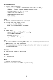
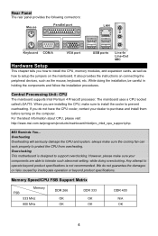
...The mainboard BIOS provides "Plug & Play" BIOS which detects the peripheral devices and expansion cards of the board automatically. z Hardware monitor is to monitor CPU's temperature/voltage. 3 Meet PC2001 audio performance requirement. On-Board Peripherals z On-Board Peripherals includes: - 1 floppy port supports 2 FDDs with 360K, 720K, 1.2M, 1.44M and 2.88Mbytes. - 1 serial port, 1 VGA port, 1 optional serial port connector JCOM1. - 1 parallel port supports SPP/EPP/ECP mode. - 8 USB 2.0 ports (Rear * 4/ Front * 4). - 3 audio (Line-In/Line-Out/Mic) ports. - 1 RJ-45 LAN Jack. z 6-channel...
...The mainboard BIOS provides "Plug & Play" BIOS which detects the peripheral devices and expansion cards of the board automatically. z Hardware monitor is to monitor CPU's temperature/voltage. 3 Meet PC2001 audio performance requirement. On-Board Peripherals z On-Board Peripherals includes: - 1 floppy port supports 2 FDDs with 360K, 720K, 1.2M, 1.44M and 2.88Mbytes. - 1 serial port, 1 VGA port, 1 optional serial port connector JCOM1. - 1 parallel port supports SPP/EPP/ECP mode. - 8 USB 2.0 ports (Rear * 4/ Front * 4). - 3 audio (Line-In/Line-Out/Mic) ports. - 1 RJ-45 LAN Jack. z 6-channel...
User Guide
Page 8
... 4 Central Processing Unit: CPU The mainboard supports Intel Pentium 4 Prescott processor. When you do not guarantee the damages or risks caused by inadequate operation or beyond product specifications is designed to setup the jumpers on the mainboard. Overclocking This motherboard is not recommended. Rear Panel The rear panel provides the following connectors: Hardware Setup This chapter tells you how to install the CPU, memory modules, and expansion...
... 4 Central Processing Unit: CPU The mainboard supports Intel Pentium 4 Prescott processor. When you do not guarantee the damages or risks caused by inadequate operation or beyond product specifications is designed to setup the jumpers on the mainboard. Overclocking This motherboard is not recommended. Rear Panel The rear panel provides the following connectors: Hardware Setup This chapter tells you how to install the CPU, memory modules, and expansion...
User Guide
Page 9
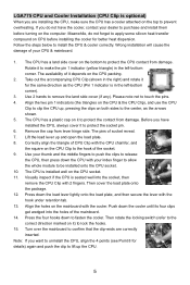
... fasten the cooler. Turn over the mainboard to protect the socket pin. 6. Remove the cap from damage. Note: If you want to the center, as the CPU (Pin 1 indicator is in the left -bottom corner). 3. Align the two pin 1 indicators (the triangles on the CPU & the CPU Clip), and use the CPU Clip to lift up and open the load plate. 8. Then cover...
... fasten the cooler. Turn over the mainboard to protect the socket pin. 6. Remove the cap from damage. Note: If you want to the center, as the CPU (Pin 1 indicator is in the left -bottom corner). 3. Align the two pin 1 indicators (the triangles on the CPU & the CPU Clip), and use the CPU Clip to lift up and open the load plate. 8. Then cover...
User Guide
Page 10
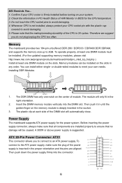
... orientation. 2. Memory modules can install either single- or double-sided modules to 2GB. Power Supply The mainboard supports ATX power supply for the CPU temperature. 3. Memory The mainboard provides two 184-pin unbuffered DDR 266 / DDR333 / DDR400 DDR SDRAM, and supports the memory size up to meet your own needs. The module will be caused. Insert the DIMM memory module vertically into the connector. Do not touch the CPU socket pins to...
... orientation. 2. Memory modules can install either single- or double-sided modules to 2GB. Power Supply The mainboard supports ATX power supply for the CPU temperature. 3. Memory The mainboard provides two 184-pin unbuffered DDR 266 / DDR333 / DDR400 DDR SDRAM, and supports the memory size up to meet your own needs. The module will be caused. Insert the DIMM memory module vertically into the connector. Do not touch the CPU socket pins to...
User Guide
Page 11
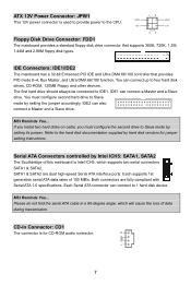
... 150 MB/s. Each Serial ATA connector can connect up to Slave mode by setting its jumper. The first hard drive should always be connected to the CPU. CD-In Connector: CD1 The connector is used to provide power to IDE1. IDE Connectors: IDE1/IDE2 The mainboard has a 32-bit Enhanced PCI IDE and Ultra DMA 66/100 controller that supports 360K, 720K, 1.2M, 1.44M and 2.88M floppy disk types. Each supports 1st generation serial ATA data rates...
... 150 MB/s. Each Serial ATA connector can connect up to Slave mode by setting its jumper. The first hard drive should always be connected to the CPU. CD-In Connector: CD1 The connector is used to provide power to IDE1. IDE Connectors: IDE1/IDE2 The mainboard has a 32-bit Enhanced PCI IDE and Ultra DMA 66/100 controller that supports 360K, 720K, 1.2M, 1.44M and 2.88M floppy disk types. Each supports 1st generation serial ATA data rates...
User Guide
Page 12
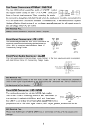
... audio ports. Fan Power Connectors: CPUFAN1/SYSFAN1 The 4-pin CPUFAN1 (processor fan) and 3-pin SYSFAN1 (system fan) support system cooling fan with Intel Front Panel I /O Connectivity Design Guide. If the mainboard has a System Hardware Monitor chipset on 9 1 the back panel will not function. 10 2 Front USB Connector: USB1/USB2 The mainboard provides two standard USB 2.0 pin headers USB1&USB2. MSI Reminds You... JFP1 is Ground and should be connected correctly, or it may cause some damage 8 HDD Reset LED Switch JFP1 Speaker 2 8 1 7 Power LED...
... audio ports. Fan Power Connectors: CPUFAN1/SYSFAN1 The 4-pin CPUFAN1 (processor fan) and 3-pin SYSFAN1 (system fan) support system cooling fan with Intel Front Panel I /O Connectivity Design Guide. If the mainboard has a System Hardware Monitor chipset on 9 1 the back panel will not function. 10 2 Front USB Connector: USB1/USB2 The mainboard provides two standard USB 2.0 pin headers USB1&USB2. MSI Reminds You... JFP1 is Ground and should be connected correctly, or it may cause some damage 8 HDD Reset LED Switch JFP1 Speaker 2 8 1 7 Power LED...
User Guide
Page 13
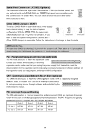
Serial Port Connector: JCOM2 (Optional) The mainboard offers one optional serial port JCOM2. With the CMOS RAM, the system can send interrupt signals to clear data. MSI Reminds You... it is turned on the rear panel), and one 9-pin male DIN connector COM A (on . PCI (Peripheral Component Interconnect) Slots The PCI slots allow you want to clear the system configuration, use the JBAT1 (Clear CMOS Jumper) to the microprocessor. Clear CMOS Jumper: JBAT1 There is on board that has a power supply from external...
Serial Port Connector: JCOM2 (Optional) The mainboard offers one optional serial port JCOM2. With the CMOS RAM, the system can send interrupt signals to clear data. MSI Reminds You... it is turned on the rear panel), and one 9-pin male DIN connector COM A (on . PCI (Peripheral Component Interconnect) Slots The PCI slots allow you want to clear the system configuration, use the JBAT1 (Clear CMOS Jumper) to the microprocessor. Clear CMOS Jumper: JBAT1 There is on board that has a power supply from external...
User Guide
Page 14
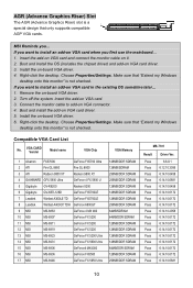
... -board VGA driver. 2. Right-click the desktop. Choose Properties/Settings. AGR (Advance Graphics Riser) Slot The AGR (Advance Graphics Riser) slot is not checked. Remove the on VGA card. 3. Connect the monitor cable to install an add-on VGA card when you first use the mainboard... 1. If you want to install an add-on VGA card in the existing OS sometime later... 1. Make sure that only supports compatible AGP VGA cards. MSI Reminds you want to add-on -board VGA driver. 4. Boot...
... -board VGA driver. 2. Right-click the desktop. Choose Properties/Settings. AGR (Advance Graphics Riser) Slot The AGR (Advance Graphics Riser) slot is not checked. Remove the on VGA card. 3. Connect the monitor cable to install an add-on VGA card when you first use the mainboard... 1. If you want to install an add-on VGA card in the existing OS sometime later... 1. Make sure that only supports compatible AGP VGA cards. MSI Reminds you want to add-on -board VGA driver. 4. Boot...
User Guide
Page 16
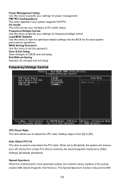
... by simultaneously pressing , , and keys. Advanced Chipset Features Use this menu for updated information. BIOS Setup Power on the screen, press key to setup the items of Award special enhanced features. Main Page Standard CMOS Features Use this menu to specify your system performance. You may also restart the system by turning it OFF and On or pressing the RESET button. Integrated Peripherals Use this menu to enter Setup. When the message below...
... by simultaneously pressing , , and keys. Advanced Chipset Features Use this menu for updated information. BIOS Setup Power on the screen, press key to setup the items of Award special enhanced features. Main Page Standard CMOS Features Use this menu to specify your system performance. You may also restart the system by turning it OFF and On or pressing the RESET button. Integrated Peripherals Use this menu to enter Setup. When the message below...
User Guide
Page 17
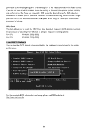
... Interference). Load BIOS Defaults Use this menu to set to [Enabled], the system will remove (turn off) clocks from [8] to [50]. BIOS Setting Password Use this menu to load the optimized default settings into the BIOS for the best system performance operations. Frequency/Voltage Control CPU Clock Ratio This item allows you to CMOS and exit setup. When set the password. PNP/PCI Configurations This entry appears if your hardware & PC health status. Save & Exit Setup Save changes to adjust the CPU ratio...
... Interference). Load BIOS Defaults Use this menu to set to [Enabled], the system will remove (turn off) clocks from [8] to [50]. BIOS Setting Password Use this menu to load the optimized default settings into the BIOS for the best system performance operations. Frequency/Voltage Control CPU Clock Ratio This item allows you to CMOS and exit setup. When set the password. PNP/PCI Configurations This entry appears if your hardware & PC health status. Save & Exit Setup Save changes to adjust the CPU ratio...
User Guide
Page 18
... setting at http://www.msi.com.tw. 14 Setting options: For CPU FSB200: [200]~[500] For CPU FSB133: [133]~[500] Load BIOS Default You can load the BIOS default values provided by modulating the pulses so that the spikes of the pulses are overclocking, because even a slight jitter can introduce a temporary boost in clock speed which may just cause your overclocked processor to select the CPU Front Side Bus clock frequency...
... setting at http://www.msi.com.tw. 14 Setting options: For CPU FSB200: [200]~[500] For CPU FSB133: [133]~[500] Load BIOS Default You can load the BIOS default values provided by modulating the pulses so that the spikes of the pulses are overclocking, because even a slight jitter can introduce a temporary boost in clock speed which may just cause your overclocked processor to select the CPU Front Side Bus clock frequency...

User Guide
Page 56
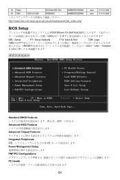
....1 的 40 USB USB HDD MP3 VCC 和 GND JCOM2(选配) 1 个 9-pin 公头 DIN JCOM1 16550A 16 bytes FIFO 清除 CMOS 跳线:JBAT1 CMOS RAM CMOS RAM CMOS RAM JBAT1(清除 CMOS 2-3 CMOS 1-2 CMOS PCI PCI BIOS 设置。 CNR CNR CNR CNR ATX PCI IRQ PCI 的 IRQ PCI 总线的 INT A# ~ INTD# 引脚: PCI Slot 1 PCI Slot 2 Order1 INT...
....1 的 40 USB USB HDD MP3 VCC 和 GND JCOM2(选配) 1 个 9-pin 公头 DIN JCOM1 16550A 16 bytes FIFO 清除 CMOS 跳线:JBAT1 CMOS RAM CMOS RAM CMOS RAM JBAT1(清除 CMOS 2-3 CMOS 1-2 CMOS PCI PCI BIOS 设置。 CNR CNR CNR CNR ATX PCI IRQ PCI 的 IRQ PCI 总线的 INT A# ~ INTD# 引脚: PCI Slot 1 PCI Slot 2 Order1 INT...

User Guide
Page 73
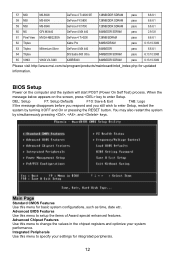
...MX440 GeForce 4 MX 440 64MB/DDR SDRAM pass 2.9.5.8 61 Pixel View MVGA-NBG25GA GeForce 4 Ti 4200 128MB/SDRAM pass 6.6.8.1 62 Triplex Xabre Pro 64MB/SDRAM pass 6.13.10.3080 63 Triplex Millennium Silver GeForce 4 MX 440 64MB/DDR pass 6.6.8.1 64 Triplex SIS Sabre 600 Ultra 64MB/...DDR SDRAM pass 6.13.10.3080 65 VINIX VINIX VX-3340 XABRE400 64MB/DDR SDRAM pass 6.13.10.3080 http://www.msi.com.tw/program/products/mainboard/mbd_index.php BIOS 設定 POST DEL DEL: Setup F7: Setup Defaults F10: Save & Exit TAB: Logo RESET Ctrl>、及
...MX440 GeForce 4 MX 440 64MB/DDR SDRAM pass 2.9.5.8 61 Pixel View MVGA-NBG25GA GeForce 4 Ti 4200 128MB/SDRAM pass 6.6.8.1 62 Triplex Xabre Pro 64MB/SDRAM pass 6.13.10.3080 63 Triplex Millennium Silver GeForce 4 MX 440 64MB/DDR pass 6.6.8.1 64 Triplex SIS Sabre 600 Ultra 64MB/...DDR SDRAM pass 6.13.10.3080 65 VINIX VINIX VX-3340 XABRE400 64MB/DDR SDRAM pass 6.13.10.3080 http://www.msi.com.tw/program/products/mainboard/mbd_index.php BIOS 設定 POST DEL DEL: Setup F7: Setup Defaults F10: Save & Exit TAB: Logo RESET Ctrl>、及

User Guide
Page 74
PNP/PCI Configurations(PNP/PCI PnP/PCI PC Health Status Frequency/Voltage Control Load BIOS Defaults BIOS BIOS Setting Password(BIOS BIOS 密碼。 Save & Exit Setup CMOS Exit Without Saving CMOS 70
PNP/PCI Configurations(PNP/PCI PnP/PCI PC Health Status Frequency/Voltage Control Load BIOS Defaults BIOS BIOS Setting Password(BIOS BIOS 密碼。 Save & Exit Setup CMOS Exit Without Saving CMOS 70

User Guide
Page 79
..., 1.44M and 2.88M FDD を 2 1 1 VGA ポート,1 optional serial port connector JCOM1. - 1 SPP/EPP/ECP 8 USB 2.0 ports x 4 x 4 ) - 3 Line-In/Line-Out/Mic) - 1 RJ-45 LAN z ICH5 AC・7 z ALC655 6 - AC97 v2.3 PC2001 LAN z Realtek 8100C - Fast Ethernet MAC 及び PHY 統合 - 10Mb/s and 100Mb/s PCI 2.2 ACPI BIOS z BIOS Plug & Play BIOS を提供 z DMI (Desktop Management Interface 寸法 z 24.5 cm...
..., 1.44M and 2.88M FDD を 2 1 1 VGA ポート,1 optional serial port connector JCOM1. - 1 SPP/EPP/ECP 8 USB 2.0 ports x 4 x 4 ) - 3 Line-In/Line-Out/Mic) - 1 RJ-45 LAN z ICH5 AC・7 z ALC655 6 - AC97 v2.3 PC2001 LAN z Realtek 8100C - Fast Ethernet MAC 及び PHY 統合 - 10Mb/s and 100Mb/s PCI 2.2 ACPI BIOS z BIOS Plug & Play BIOS を提供 z DMI (Desktop Management Interface 寸法 z 24.5 cm...
User Guide
Page 88
64 Triplex SIS Sabre 600 Ultra 64MB/DDR SDRAM 65 VINIX VINIX VX-3340 XABRE400 64MB/DDR SDRAM http://www.msi.com.tw/program/products/mainboard/mbd_index.php pass 6.13.10.3080 pass 6.13.10.3080 BIOS Setup POST(Power On Self Test DEL DEL: Setup F7: Setup Defaults F10: Save & Exit TAB: Logo 、、 Standard CMOS Features Advanced BIOS Features Advanced Chipset Features Integrated Peripherals IDE I/O Power Management Setup PNP/PCI Configurations PCI PC Health 84
64 Triplex SIS Sabre 600 Ultra 64MB/DDR SDRAM 65 VINIX VINIX VX-3340 XABRE400 64MB/DDR SDRAM http://www.msi.com.tw/program/products/mainboard/mbd_index.php pass 6.13.10.3080 pass 6.13.10.3080 BIOS Setup POST(Power On Self Test DEL DEL: Setup F7: Setup Defaults F10: Save & Exit TAB: Logo 、、 Standard CMOS Features Advanced BIOS Features Advanced Chipset Features Integrated Peripherals IDE I/O Power Management Setup PNP/PCI Configurations PCI PC Health 84
User Guide
Page 89
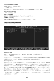
Frequency/Voltage Control Load BIOS Defaults BIOS BIOS Setting Password Save & Exit Setup CMOS Exit Without Saving CMOS Frequency/Voltage Control CPU Clock Ratio CPU Vcore 8]から[50 Auto Detect PCI Clk PCI Enabled(有効)と Disabled Spread Spectrum EMI Spread Spectrum EMI EMI Disabled EMI Enabled EMI Disabled 85
Frequency/Voltage Control Load BIOS Defaults BIOS BIOS Setting Password Save & Exit Setup CMOS Exit Without Saving CMOS Frequency/Voltage Control CPU Clock Ratio CPU Vcore 8]から[50 Auto Detect PCI Clk PCI Enabled(有効)と Disabled Spread Spectrum EMI Spread Spectrum EMI EMI Disabled EMI Enabled EMI Disabled 85

