User Guide
Page 2
... are the properties of AMD Corporation. func=service Contact our technical staff at: http://ocss.msi.com.tw ii Award® is a registered trademark of purchase or local distributor. Visit the MSI website for further guidance. W indows® NT/XP/Vista are registered trademarks or trademarks.... Alternatively, please try the following help resources for FAQ, technical guide, BIOS updates, driver updates, and other countries. We take every care in the United States and/or other information: http://global.msi.com.tw/index.php? Intel® and Pentium® are under continual...
... are the properties of AMD Corporation. func=service Contact our technical staff at: http://ocss.msi.com.tw ii Award® is a registered trademark of purchase or local distributor. Visit the MSI website for further guidance. W indows® NT/XP/Vista are registered trademarks or trademarks.... Alternatively, please try the following help resources for FAQ, technical guide, BIOS updates, driver updates, and other countries. We take every care in the United States and/or other information: http://global.msi.com.tw/index.php? Intel® and Pentium® are under continual...
User Guide
Page 8
... ...2-8 Back Panel ...2-9 Connectors ...2-11 Button ...2-19 Slots ...2-22 LED Status Indicators 2-26 Chapter 3 BIOS Setup 3-1 Entering Setup ...3-2 The Main Menu ...3-4 Standard CMOS Features 3-6 Advanced BIOS Features 3-8 Integrated Peripherals 3-11 Power Management Setup 3-13 H/W Monitor ...3-16 Green Power ...3-17 BIOS Setting Password 3-18 Cell Menu ...3-19 User Setting ...3-26 M-Flash ...3-27 Load Fail-Safe...
... ...2-8 Back Panel ...2-9 Connectors ...2-11 Button ...2-19 Slots ...2-22 LED Status Indicators 2-26 Chapter 3 BIOS Setup 3-1 Entering Setup ...3-2 The Main Menu ...3-4 Standard CMOS Features 3-6 Advanced BIOS Features 3-8 Integrated Peripherals 3-11 Power Management Setup 3-13 H/W Monitor ...3-16 Green Power ...3-17 BIOS Setting Password 3-18 Cell Menu ...3-19 User Setting ...3-26 M-Flash ...3-27 Load Fail-Safe...
User Guide
Page 26
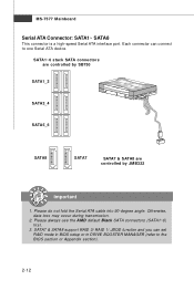
... SATA connectors are controlled by SB750 SATA1_2 SATA3_4 SATA5_6 SATA8 SATA7 SATA7 & SATA8 are controlled by JMB322 Important 1. Each connector can set RAID mode in BIOS setup or in DRIVE BOOSTER MANAGER (refer to one Serial ATA device. Otherwise, data loss may occur during transmission. 2. SATA7 & SATA8 support RAID 0/ RAID 1/ JBOD...
... SATA connectors are controlled by SB750 SATA1_2 SATA3_4 SATA5_6 SATA8 SATA7 SATA7 & SATA8 are controlled by JMB322 Important 1. Each connector can set RAID mode in BIOS setup or in DRIVE BOOSTER MANAGER (refer to one Serial ATA device. Otherwise, data loss may occur during transmission. 2. SATA7 & SATA8 support RAID 0/ RAID 1/ JBOD...
User Guide
Page 27
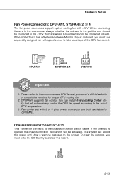
... SE NS OR +1 2V GND CPUFAN1 GND +1 2V SE NS OR SYSFAN1/3/4 SYSFAN2 Important 1. To clear the warning, you must enter the BIOS utility and clear the record. If the chassis is the positive and should be activated. CPUFAN1 supports fan control. GND CINTRU 2 1 2-13 ... mechanism will automatically control the CPU fan speed according to GND. Chassis Intrusion Connector: JCI1 This connector connects to the +12V; If the motherboard has a System Hardware Monitor chipset on the screen. W hen connecting the wire to the connectors, always note that will be connected to...
... SE NS OR +1 2V GND CPUFAN1 GND +1 2V SE NS OR SYSFAN1/3/4 SYSFAN2 Important 1. To clear the warning, you must enter the BIOS utility and clear the record. If the chassis is the positive and should be activated. CPUFAN1 supports fan control. GND CINTRU 2 1 2-13 ... mechanism will automatically control the CPU fan speed according to GND. Chassis Intrusion Connector: JCI1 This connector connects to the +12V; If the motherboard has a System Hardware Monitor chipset on the screen. W hen connecting the wire to the connectors, always note that will be connected to...
User Guide
Page 34
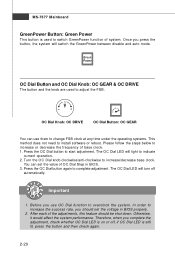
... Power This button is used to adjust the FSB. OC Dial Knob: OC DRIVE OC Dial Button: OC GEAR You can set the voltage in BIOS. 3. Press the OC Dial button to increase/decrease base clock. Before you press the button, the system will light to indicate current operation. 2. Please follow... FSB clock at any time under the operating systems. This method does not need to increase or decrease the frequency of OC Dial Step in BIOS properly. 2. OC Dial Button and OC Dial Knob: OC GEAR & OC DRIVE The button and the knob are used to complete adjustment. Press the OC...
... Power This button is used to adjust the FSB. OC Dial Knob: OC DRIVE OC Dial Button: OC GEAR You can set the voltage in BIOS. 3. Press the OC Dial button to increase/decrease base clock. Before you press the button, the system will light to indicate current operation. 2. Please follow... FSB clock at any time under the operating systems. This method does not need to increase or decrease the frequency of OC Dial Step in BIOS properly. 2. OC Dial Button and OC Dial Knob: OC GEAR & OC DRIVE The button and the knob are used to complete adjustment. Press the OC...
User Guide
Page 35
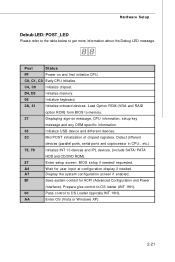
... and Power Interface). B1 Save system context for user input at configuration display if needed / requested. Load Option ROM (VGA and RAID option ROM) form BIOS to get more information about the Debug LED message. Post Status FF Power on message, CPU information, setup key message and any OEM specific information...
... and Power Interface). B1 Save system context for user input at configuration display if needed / requested. Load Option ROM (VGA and RAID option ROM) form BIOS to get more information about the Debug LED message. Post Status FF Power on message, CPU information, setup key message and any OEM specific information...
User Guide
Page 36
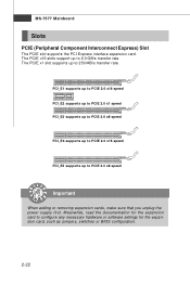
... expansion card. The PCIE x16 slots support up to configure any necessary hardware or software settings for the expansion card, such as jumpers, switches or BIOS configuration. 2-22
... expansion card. The PCIE x16 slots support up to configure any necessary hardware or software settings for the expansion card, such as jumpers, switches or BIOS configuration. 2-22
User Guide
Page 37
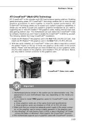
...proc ess ors to work . W ith two cards installed, an CrossFireXTM Video Link cable is the ultimate multi-GPU performance gaming platform. Motherboard photos shown in BIOS by yourself. Only Windows® XP with Service Pack 2 (SP2) or later & Windows® XP Profes -sional x64 Edition &... Windows® Vista support the CrossFireXTM function. 5.This motherboard supports up to improve sys tem performance. CrossFireXTM Video Link cable Important 1. Enabling...
...proc ess ors to work . W ith two cards installed, an CrossFireXTM Video Link cable is the ultimate multi-GPU performance gaming platform. Motherboard photos shown in BIOS by yourself. Only Windows® XP with Service Pack 2 (SP2) or later & Windows® XP Profes -sional x64 Edition &... Windows® Vista support the CrossFireXTM function. 5.This motherboard supports up to improve sys tem performance. CrossFireXTM Video Link cable Important 1. Enabling...
User Guide
Page 39
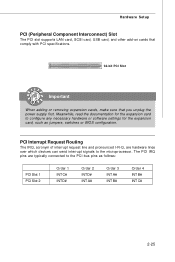
... the microprocessor. The PCI IRQ pins are hardware lines over which devices can send interrupt signals to the PCI bus pins as jumpers, switches or BIOS configuration. Hardware Setup PCI (Peripheral Component Interconnect) Slot The PCI slot supports LAN card, SCSI card, USB card, and other add-on cards that comply...
... the microprocessor. The PCI IRQ pins are hardware lines over which devices can send interrupt signals to the PCI bus pins as jumpers, switches or BIOS configuration. Hardware Setup PCI (Peripheral Component Interconnect) Slot The PCI slot supports LAN card, SCSI card, USB card, and other add-on cards that comply...

User Guide
Page 42
You may need to run the Setup program when: ² An error message appears on the BIOS Setup program and allows you to run SETUP. ² You want to configure the system for customized features. 3-1 Chapter 3 BIOS Setup BIOS Setup This chapter provides information on the screen during the system booting up, and requests you to change the default settings for optimum use.
You may need to run the Setup program when: ² An error message appears on the BIOS Setup program and allows you to run SETUP. ² You want to configure the system for customized features. 3-1 Chapter 3 BIOS Setup BIOS Setup This chapter provides information on the screen during the system booting up, and requests you to change the default settings for optimum use.

User Guide
Page 43
... under continuous update for reference only. 2. Important 1. Upon boot-up, the 1st line appearing after the memory count is usually in this BIOS was released. 3-2 W hen the message below appears on the computer and the system will start POST (Power On Self Test) process. It ... 7th - 8th digit refers to enter Setup, restart the system by simultaneously pressing , , and keys. You may be slightly different from the latest BIOS and should be held for better system performance. Therefore, the description may also restart the system by turning it OFF and On or pressing the...
... under continuous update for reference only. 2. Important 1. Upon boot-up, the 1st line appearing after the memory count is usually in this BIOS was released. 3-2 W hen the message below appears on the computer and the system will start POST (Power On Self Test) process. It ... 7th - 8th digit refers to enter Setup, restart the system by simultaneously pressing , , and keys. You may be slightly different from the latest BIOS and should be held for better system performance. Therefore, the description may also restart the system by turning it OFF and On or pressing the...

User Guide
Page 44
... up the sub-menu. The Help screen lists the appropriate keys to use the arrow keys ( ↑↓ ) to select the item. General Help The BIOS setup program provides a General Help screen. Then you want to return to the main menu, just press the . Main Menu The main menu lists the... in the right view) appears to the left hand Move to the item in the left of the screen. You can call up this field. BIOS Setup Control Keys Enter> Move to the previous item Move to the next item Move to the item in the right hand Select the item...
... up the sub-menu. The Help screen lists the appropriate keys to use the arrow keys ( ↑↓ ) to select the item. General Help The BIOS setup program provides a General Help screen. Then you want to return to the main menu, just press the . Main Menu The main menu lists the... in the right view) appears to the left hand Move to the item in the left of the screen. You can call up this field. BIOS Setup Control Keys Enter> Move to the previous item Move to the next item Move to the item in the right hand Select the item...
User Guide
Page 45
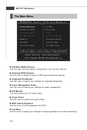
... time, date etc. Power Management Setup Use this menu to setup the items of AMI® special enhanced features. Advanced BIOS Features Use this menu to specify your settings for BIOS. Green Power Use this menu to specify your settings for power management. Cell Menu Use this menu to specify the power... to set the password for frequency/voltage control and overclocking. 3-4 MS-7577 Mainboard The Main Menu Standard CMOS Features Use this menu for integrated peripherals. BIOS Setting Password Use this menu to specify your PC health status.
... time, date etc. Power Management Setup Use this menu to setup the items of AMI® special enhanced features. Advanced BIOS Features Use this menu to specify your settings for BIOS. Green Power Use this menu to specify your settings for power management. Cell Menu Use this menu to specify the power... to set the password for frequency/voltage control and overclocking. 3-4 MS-7577 Mainboard The Main Menu Standard CMOS Features Use this menu for integrated peripherals. BIOS Setting Password Use this menu to specify your PC health status.
User Guide
Page 46
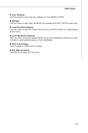
Load Optimized Defaults Use this menu to load the default values set by the motherboard manufacturer specifically for BIOS. Save & Exit Setup Save changes to read/ flash the BIOS from CMOS for optimal performance of the motherboard. BIOS Setup User Settings Use this menu to save/ load your settings to/ from storage drive (FAT/ FAT32 format only). Load Fail-Safe Defaults Use this menu to CMOS and exit setup. M-Flash Use this menu to load the default values set by the BIOS vendor for stable system performance. Exit Without Saving Abandon all changes and exit setup. 3-5
Load Optimized Defaults Use this menu to load the default values set by the motherboard manufacturer specifically for BIOS. Save & Exit Setup Save changes to read/ flash the BIOS from CMOS for optimal performance of the motherboard. BIOS Setup User Settings Use this menu to save/ load your settings to/ from storage drive (FAT/ FAT32 format only). Load Fail-Safe Defaults Use this menu to CMOS and exit setup. M-Flash Use this menu to load the default values set by the BIOS vendor for stable system performance. Exit Without Saving Abandon all changes and exit setup. 3-5
User Guide
Page 47
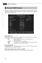
...:DD:YY) This allows you to set the system time that you want in each item. month The month from Sun to Sat, determined by BIOS. day Day of the week, from Jan. Read-only. The format is . IDE Primary Master/ Slave, SATA1~8, E-SATA Press to 31 can be keyed by...
...:DD:YY) This allows you to set the system time that you want in each item. month The month from Sun to Sat, determined by BIOS. day Day of the week, from Jan. Read-only. The format is . IDE Primary Master/ Slave, SATA1~8, E-SATA Press to 31 can be keyed by...
User Guide
Page 48
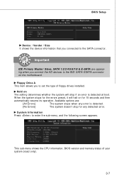
... is detected. Available options are appearing when you connect the HD devices to the SATA connector. This sub-menu shows the CPU information, BIOS version and memory status of floppy drives installed. Important IDE Primary Master/ Slave, SATA 1/2/3/4/5/6/7/8 & E-SATA are : [All Errors] [No... Errors] The system stops when any detected error. Hold on The setting determines whether the system will halt on the motherboard. BIOS Setup Device / Vender / Size It shows the device information that you connected to the IDE/ SATA/ ESATA connector on for any error is...
... is detected. Available options are appearing when you connect the HD devices to the SATA connector. This sub-menu shows the CPU information, BIOS version and memory status of floppy drives installed. Important IDE Primary Master/ Slave, SATA 1/2/3/4/5/6/7/8 & E-SATA are : [All Errors] [No... Errors] The system stops when any detected error. Hold on The setting determines whether the system will halt on the motherboard. BIOS Setup Device / Vender / Size It shows the device information that you connected to the IDE/ SATA/ ESATA connector on for any error is...
User Guide
Page 49
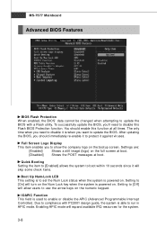
...is powered on . Setting to [Off] will expand available IRQ resources for the system. 3-8 Due to compliance with a Flash utility. After updating the BIOS, you to protect it is used to use the arrow keys on the bootup screen. IOAPIC Function This field is when you 'll need to... update the BIOS. Enabling APIC mode will allow users to enable or disable the APIC (Advanced Programmable Interrupt Controller). Full Screen Logo Display This item enables you...
...is powered on . Setting to [Off] will expand available IRQ resources for the system. 3-8 Due to compliance with a Flash utility. After updating the BIOS, you to protect it is used to use the arrow keys on the bootup screen. IOAPIC Function This field is when you 'll need to... update the BIOS. Enabling APIC mode will allow users to enable or disable the APIC (Advanced Programmable Interrupt Controller). Full Screen Logo Display This item enables you...
User Guide
Page 50
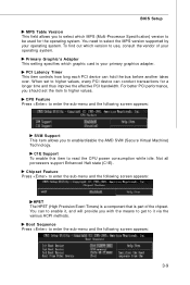
... the MPS version supported by your primary graphics adapter. Chipset Feature Press to be used for a longer time and thus improve the effective PCI bandwidth. BIOS Setup MPS Table Version This field allows you to enable/disable the AMD SVM (Secure Virtual Machine) Tec hn ology. CPU Feature Press to enter...
... the MPS version supported by your primary graphics adapter. Chipset Feature Press to be used for a longer time and thus improve the effective PCI bandwidth. BIOS Setup MPS Table Version This field allows you to enable/disable the AMD SVM (Secure Virtual Machine) Tec hn ology. CPU Feature Press to enter...
User Guide
Page 51
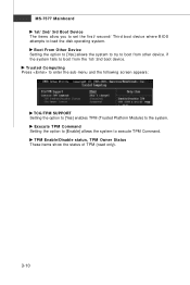
... TPM (read only). 3-10 MS-7577 Mainboard 1st/ 2nd/ 3rd Boot Device The items allow you to set the first/ second/ Third boot device where BIOS attempts to boot from other device. Boot From Other Device Setting the option to [Yes] allows the system to try to boot from the 1st...
... TPM (read only). 3-10 MS-7577 Mainboard 1st/ 2nd/ 3rd Boot Device The items allow you to set the first/ second/ Third boot device where BIOS attempts to boot from other device. Boot From Other Device Setting the option to [Yes] allows the system to try to boot from the 1st...
User Guide
Page 52
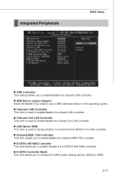
Integrated Peripherals BIOS Setup USB Controller This setting allows you to configure E-SATA mode. Onboard 2nd LAN Controller This item is used to decide whether to invoke the ...
Integrated Peripherals BIOS Setup USB Controller This setting allows you to configure E-SATA mode. Onboard 2nd LAN Controller This item is used to decide whether to invoke the ...


