User Guide
Page 10
Designed to fit the advanced AMD® Phenom II X4/ X3 and Athlon X4/ X3/ X2 AM 3 processor, the 790FX-GD70 Series deliver a high performance and professional desktop platform solution. 1-1 The 790FX-GD70 Series motherboards are based on AMD® 790FX & SB750 chipset for choosing the 790FX-GD70 Series (MS7577 v1.X) ATX motherboard. Getting Started Chapter 1 Getting Started Thank you for optimal system efficiency.
Designed to fit the advanced AMD® Phenom II X4/ X3 and Athlon X4/ X3/ X2 AM 3 processor, the 790FX-GD70 Series deliver a high performance and professional desktop platform solution. 1-1 The 790FX-GD70 Series motherboards are based on AMD® 790FX & SB750 chipset for choosing the 790FX-GD70 Series (MS7577 v1.X) ATX motherboard. Getting Started Chapter 1 Getting Started Thank you for optimal system efficiency.
User Guide
Page 11
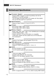
Supports storage and data transfers at up to 3.0 Gb/s ESATA - msi.com.tw/index.php?func=cpuform2) HyperTransport - Supports 2 IEEE1394 ports (rear x 1, front x 1) Audio - HD..., for more information on compatible components, please visit http://global.msi.com.tw/index.php? Up to 5.2 GT/s Chipset - SATA7~8 ports by Realtek® RTL8111DL IEEE 1394 (optional) - North Bridge: AMD® 790FX chipset - Supports Dual Gigabit LAN by JMicron® JMB322 -... with jack sensing IDE - 1 IDE port by AMD® SB750 - MS-7577 Mainboard Motherboard Specifications Processor Support -
Supports storage and data transfers at up to 3.0 Gb/s ESATA - msi.com.tw/index.php?func=cpuform2) HyperTransport - Supports 2 IEEE1394 ports (rear x 1, front x 1) Audio - HD..., for more information on compatible components, please visit http://global.msi.com.tw/index.php? Up to 5.2 GT/s Chipset - SATA7~8 ports by Realtek® RTL8111DL IEEE 1394 (optional) - North Bridge: AMD® 790FX chipset - Supports Dual Gigabit LAN by JMicron® JMB322 -... with jack sensing IDE - 1 IDE port by AMD® SB750 - MS-7577 Mainboard Motherboard Specifications Processor Support -
User Guide
Page 13
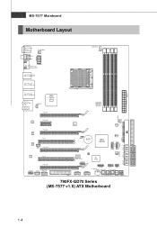
...3 D I /O Chip SATA5-6 JUSB1 JUS B2 OC DRIVE J TPM1 OC GEAR J FP1 JFP2 C L R_ C M OS 1 Gr een Power RESET1 POWER1 790FX-GD70 Series (MS-7577 v1.X) ATX Motherboard 1-4 JMB362 JBAT1 BATT + AMD SB750 JMB322 IDE1 SATA7 SATA8 SATA3-4 S ATA1-2 SYSFAN2 FDD 1 JCI1 POS T_LED J COM1 I MM 4 Top: LAN Jack Bottom...: USB ports AMD 790FX T:L i ne - O u t B:Mi c T:RS-Out M:CS-Out B:SS-Out ...
...3 D I /O Chip SATA5-6 JUSB1 JUS B2 OC DRIVE J TPM1 OC GEAR J FP1 JFP2 C L R_ C M OS 1 Gr een Power RESET1 POWER1 790FX-GD70 Series (MS-7577 v1.X) ATX Motherboard 1-4 JMB362 JBAT1 BATT + AMD SB750 JMB322 IDE1 SATA7 SATA8 SATA3-4 S ATA1-2 SYSFAN2 FDD 1 JCI1 POS T_LED J COM1 I MM 4 Top: LAN Jack Bottom...: USB ports AMD 790FX T:L i ne - O u t B:Mi c T:RS-Out M:CS-Out B:SS-Out ...
User Guide
Page 14
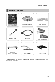
Packing Checklist Getting Started MSI motherboard MSI Driver/Utility CD Back IO Shield Power Cable SATA Cable IDE/ Floppy Cable CrossFire Video Link Cable USB Bracket User's Guide * The pictures are for reference only and may vary from the packing contents of the product you purchased. 1-5
Packing Checklist Getting Started MSI motherboard MSI Driver/Utility CD Back IO Shield Power Cable SATA Cable IDE/ Floppy Cable CrossFire Video Link Cable USB Bracket User's Guide * The pictures are for reference only and may vary from the packing contents of the product you purchased. 1-5
User Guide
Page 17
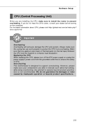
For the latest information about CPU, please visit http://global.msi.com.tw/index.php? func=cpuform2 Important Overheating Overheating will seriously damage the CPU and system. Overclocking This motherboard is not recommended. We do not have the CPU cooler, consult your components are installing the CPU...thermal tape) between the CPU and the heatsink to support overclocking. Replacing the CPU While replacing the CPU, always turn off the ATX power supply or unplug the power supply's power cord from overheating. Always make sure your dealer before turning on the computer. Any...
For the latest information about CPU, please visit http://global.msi.com.tw/index.php? func=cpuform2 Important Overheating Overheating will seriously damage the CPU and system. Overclocking This motherboard is not recommended. We do not have the CPU cooler, consult your components are installing the CPU...thermal tape) between the CPU and the heatsink to support overclocking. Replacing the CPU While replacing the CPU, always turn off the ATX power supply or unplug the power supply's power cord from overheating. Always make sure your dealer before turning on the computer. Any...
User Guide
Page 18
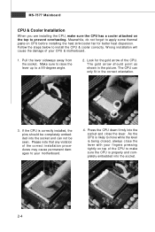
... angle. 2. The CPU can not be seen. If the CPU is being closed, always close the lever. Please note that any violation of your motherboard. 4. Make sure to raise the lever up to install the CPU & cooler correctly. T he gold arrow s hould point as shown in the correct... CPU. Look for better heat dispersion. W rong installation will cause the damage of the correct installation procedures may cause permanent damages to your CPU & motherboard. 1. MS-7577 Mainboard CPU & Cooler Installation W hen you are installing the CPU, make sure the CPU has a cooler attached on top of...
... angle. 2. The CPU can not be seen. If the CPU is being closed, always close the lever. Please note that any violation of your motherboard. 4. Make sure to raise the lever up to install the CPU & cooler correctly. T he gold arrow s hould point as shown in the correct... CPU. Look for better heat dispersion. W rong installation will cause the damage of the correct installation procedures may cause permanent damages to your CPU & motherboard. 1. MS-7577 Mainboard CPU & Cooler Installation W hen you are installing the CPU, make sure the CPU has a cooler attached on top of...
User Guide
Page 19
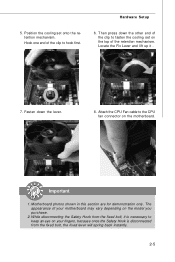
Attach the CPU Fan cable to the CPU fan connector on the model you purchase. 2. Motherboard photos shown in this section are for demonstration only. Hook one end of the retention mechanism. Fasten down the other end of the clip to .... 8. Hardware Setup 5. Important 1. While disconnecting the Safety Hook from the fixed bolt, the fixed lever will spring back instantly. 2-5 Position the cooling set on your motherboard may vary depending on the...
Attach the CPU Fan cable to the CPU fan connector on the model you purchase. 2. Motherboard photos shown in this section are for demonstration only. Hook one end of the retention mechanism. Fasten down the other end of the clip to .... 8. Hardware Setup 5. Important 1. While disconnecting the Safety Hook from the fixed bolt, the fixed lever will spring back instantly. 2-5 Position the cooling set on your motherboard may vary depending on the...
User Guide
Page 22
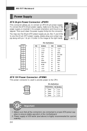
... the power supply is highly recommended for system stability. 2-8 MS-7577 Mainboard Power Supply ATX 24-pin Power Connector: JPWR1 This connector allows you to ensure stable operation of the motherboard. 2. To connect the ATX 24-pin power supply, make sure the plug of 450 watts (and above) is ...inserted in the proper orientation and the pins are connected to proper ATX power supplies to connect an ATX 24-pin power supply.
... the power supply is highly recommended for system stability. 2-8 MS-7577 Mainboard Power Supply ATX 24-pin Power Connector: JPWR1 This connector allows you to ensure stable operation of the motherboard. 2. To connect the ATX 24-pin power supply, make sure the plug of 450 watts (and above) is ...inserted in the proper orientation and the pins are connected to proper ATX power supplies to connect an ATX 24-pin power supply.
User Guide
Page 27
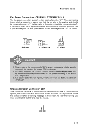
... for proper CPU cooling fan. 2. W hen connecting the wire to the actual CPU temperature. 3. the black wire is Ground and should be activated. If the motherboard has a System Hardware Monitor chipset on the screen. GND CINTRU 2 1 2-13
... for proper CPU cooling fan. 2. W hen connecting the wire to the actual CPU temperature. 3. the black wire is Ground and should be activated. If the motherboard has a System Hardware Monitor chipset on the screen. GND CINTRU 2 1 2-13
User Guide
Page 33
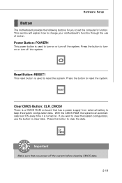
...button to turnon or turn-off the system before clearing CMOS data. 2-19 If you to set the computer's function. Hardware Setup Button The motherboard provides the following buttons for you want to clear the system configuration, use of button. Reset Button: RESET1 This reset button is a CMOS ... the button to keep the system configuration data. This section will explain how to clear the data. Press the button to change your motherboard's function through the use the button to clear data. Important Make sure that has a power supply from external battery to reset the system.
...button to turnon or turn-off the system before clearing CMOS data. 2-19 If you to set the computer's function. Hardware Setup Button The motherboard provides the following buttons for you want to clear the system configuration, use of button. Reset Button: RESET1 This reset button is a CMOS ... the button to keep the system configuration data. This section will explain how to clear the data. Press the button to change your motherboard's function through the use the button to clear data. Important Make sure that has a power supply from external battery to reset the system.
User Guide
Page 37
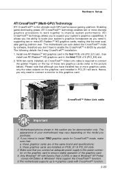
...XP Profes -sional x64 Edition & Windows® Vista support the CrossFireXTM function. 5.This motherboard supports up to enable the CrossFireXTM in this the most scalable gaming platform ever. The motherboard can auto detect the CrossFireXTM mode by yourself. Make sure that you connect an adequate power... you don't have installed two or more ATI RadeonTM HD graphics cards, making this section are of the graphics card. 4. Motherboard photos shown in BIOS by software, therefore you the ability to ensure stable operation of the same brand and specifications; If you...
...XP Profes -sional x64 Edition & Windows® Vista support the CrossFireXTM function. 5.This motherboard supports up to enable the CrossFireXTM in this the most scalable gaming platform ever. The motherboard can auto detect the CrossFireXTM mode by yourself. Make sure that you connect an adequate power... you don't have installed two or more ATI RadeonTM HD graphics cards, making this section are of the graphics card. 4. Motherboard photos shown in BIOS by software, therefore you the ability to ensure stable operation of the same brand and specifications; If you...
User Guide
Page 46
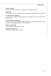
Save & Exit Setup Save changes to read/ flash the BIOS from CMOS for stable system performance. Exit Without Saving Abandon all changes and exit setup. 3-5 Load Fail-Safe Defaults Use this menu to save/ load your settings to/ from storage drive (FAT/ FAT32 format only). BIOS Setup User Settings Use this menu to load the default values set by the BIOS vendor for BIOS. M-Flash Use this menu to load the default values set by the motherboard manufacturer specifically for optimal performance of the motherboard. Load Optimized Defaults Use this menu to CMOS and exit setup.
Save & Exit Setup Save changes to read/ flash the BIOS from CMOS for stable system performance. Exit Without Saving Abandon all changes and exit setup. 3-5 Load Fail-Safe Defaults Use this menu to save/ load your settings to/ from storage drive (FAT/ FAT32 format only). BIOS Setup User Settings Use this menu to load the default values set by the BIOS vendor for BIOS. M-Flash Use this menu to load the default values set by the motherboard manufacturer specifically for optimal performance of the motherboard. Load Optimized Defaults Use this menu to CMOS and exit setup.
User Guide
Page 48
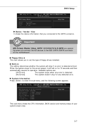
Hold on the motherboard. This sub-menu shows the CPU information, BIOS version and memory status of floppy drives installed. Important IDE Primary Master/ Slave, SATA 1/2/3/4/5/6/7/8 & E-SATA are : [All ...
Hold on the motherboard. This sub-menu shows the CPU information, BIOS version and memory status of floppy drives installed. Important IDE Primary Master/ Slave, SATA 1/2/3/4/5/6/7/8 & E-SATA are : [All ...
User Guide
Page 57
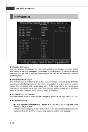
... FAN/ SYS FAN 1/ 2/ 3/ 4 Speed, CPU Vcore, 3.3V, 5V, 12V These items display the current status of all fans' speeds. 3-16 CPU Smart FAN Target The motherboard provides the Smart Fan function which can select a fan target value here. If the current CPU fan temperature reaches to the target value, the smart...
... FAN/ SYS FAN 1/ 2/ 3/ 4 Speed, CPU Vcore, 3.3V, 5V, 12V These items display the current status of all fans' speeds. 3-16 CPU Smart FAN Target The motherboard provides the Smart Fan function which can select a fan target value here. If the current CPU fan temperature reaches to the target value, the smart...
User Guide
Page 58
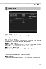
Motherboard LED Control This item is used to reach the best power saving function. Read only. Green Power BIOS Setup CPU PWM Phase Control W hen set ... loading of CPU to control the power phase LEDs of the system. GreenPower Genie----ICore/ I12V These items show the power consumption & efficiency of the motherboard. -----
Motherboard LED Control This item is used to reach the best power saving function. Read only. Green Power BIOS Setup CPU PWM Phase Control W hen set ... loading of CPU to control the power phase LEDs of the system. GreenPower Genie----ICore/ I12V These items show the power consumption & efficiency of the motherboard. -----
User Guide
Page 65
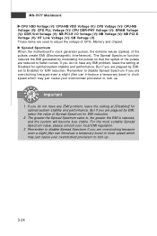
... local EMI regulation. 3. If you are plagued by modulating the pulses so that the spikes of Spread Spectrum for EMI reduction. Spread Spectrum W hen the motherboard's clock generator pulses, the extreme values (spikes) of CPU, Memory and chipset. Remember to lock up . 3-24 Important 1. The Spread Spectrum function reduces the EMI...
... local EMI regulation. 3. If you are plagued by modulating the pulses so that the spikes of Spread Spectrum for EMI reduction. Spread Spectrum W hen the motherboard's clock generator pulses, the extreme values (spikes) of CPU, Memory and chipset. Remember to lock up . 3-24 Important 1. The Spread Spectrum function reduces the EMI...
User Guide
Page 66
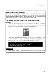
... automatically. Two ways to continue....... The previous overclocking had failed, and system will not be under our product warranty. BIOS Setup Failed Overclocking Resolution This motherboard supports overclocking greatly. Any risk or damge resulting from failed overclocking... However, please make sure your system from improper operation will restore its defaults setting...
... automatically. Two ways to continue....... The previous overclocking had failed, and system will not be under our product warranty. BIOS Setup Failed Overclocking Resolution This motherboard supports overclocking greatly. Any risk or damge resulting from failed overclocking... However, please make sure your system from improper operation will restore its defaults setting...
User Guide
Page 71
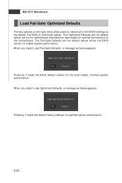
.... 3-30 MS-7577 Mainboard Load Fail-Safe/ Optimized Defaults The two options on the main menu allow users to restore all of the motherboard. W hen you select Load Optimized Defaults, a message as below appears: Pressing Y loads the default factory settings for the most stable,... minimal system performance. The Fail-Safe Defaults are the default values set by the motherboard manufacturer specifically for stable system performance. The Optimized Defaults are the default values set by the BIOS vendor for optimal performance of the...
.... 3-30 MS-7577 Mainboard Load Fail-Safe/ Optimized Defaults The two options on the main menu allow users to restore all of the motherboard. W hen you select Load Optimized Defaults, a message as below appears: Pressing Y loads the default factory settings for the most stable,... minimal system performance. The Fail-Safe Defaults are the default values set by the motherboard manufacturer specifically for stable system performance. The Optimized Defaults are the default values set by the BIOS vendor for optimal performance of the...
User Guide
Page 93
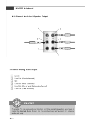
a A-22 Or, the motherboard will support 5.1 channel audio-out only. MS-7577 Mainboard n 8-Channel Mode for 8-Speaker Output 1 4 2 5 3 6 8-Channel Analog Audio Output 1 Line In 2 Line Out (Front channels) 3 MIC 4 Line Out (Rear channels) 5 Line Out (Center and Subwoofer channel) 6 Line Out (Side channels) Important To enable 7.1 channel audio-out function on Vista operating system, you have to install the Realtek Audio Driver.
a A-22 Or, the motherboard will support 5.1 channel audio-out only. MS-7577 Mainboard n 8-Channel Mode for 8-Speaker Output 1 4 2 5 3 6 8-Channel Analog Audio Output 1 Line In 2 Line Out (Front channels) 3 MIC 4 Line Out (Rear channels) 5 Line Out (Center and Subwoofer channel) 6 Line Out (Side channels) Important To enable 7.1 channel audio-out function on Vista operating system, you have to install the Realtek Audio Driver.
User Guide
Page 94
Operation system: W indows XP or up. 4. Before you install the Overclocking Center, please make sure the system has meet the following requirements: 1. 256MB system memory. 2. DVD-ROM drive for software installation. 3. Overclocking Center Appendix B Overclocking Center Overclocking Center, the most useful and powerful utility that MSI has spent much research and efforts to develop, helps users to monitor or configure the hardware status of MSI Motherboard in windows, such as CPU clock, voltage, fan speed and temperature. DotNet Frame Work 2.0 B-1
Operation system: W indows XP or up. 4. Before you install the Overclocking Center, please make sure the system has meet the following requirements: 1. 256MB system memory. 2. DVD-ROM drive for software installation. 3. Overclocking Center Appendix B Overclocking Center Overclocking Center, the most useful and powerful utility that MSI has spent much research and efforts to develop, helps users to monitor or configure the hardware status of MSI Motherboard in windows, such as CPU clock, voltage, fan speed and temperature. DotNet Frame Work 2.0 B-1


