User Guide
Page 2
...MSI website for 785GM-E51 & 760GM-E51 Date August 2009 Technical Support If a problem arises with your place of its contents. Revision History Revision V1.4 Revision History Release for FAQ, technical guide, BIOS updates, driver updates, and other information: http://www.msi.com/index.php?func=service...Windows® is registered trademarks of Microsoft Corporation. ■ AMI® is registered trademark of American Megatrends Inc. ■ Award® is a registered trademark of Phoenix Technologies Ltd. ■ Sound Blaster® is registered trademark of Creative Technology...
...MSI website for 785GM-E51 & 760GM-E51 Date August 2009 Technical Support If a problem arises with your place of its contents. Revision History Revision V1.4 Revision History Release for FAQ, technical guide, BIOS updates, driver updates, and other information: http://www.msi.com/index.php?func=service...Windows® is registered trademarks of Microsoft Corporation. ■ AMI® is registered trademark of American Megatrends Inc. ■ Award® is a registered trademark of Phoenix Technologies Ltd. ■ Sound Blaster® is registered trademark of Creative Technology...
User Guide
Page 8
... 1 Getting Started 1-1 Mainboard Specifications 1-2 Mainboard Layout 1-4 Packing Checklist 1-5 Chapter 2 Hardware Setup 2-1 Quick Components Guide 2-2 CPU (Central Processing Unit 2-3 Memory 2-6 Power Supply 2-8 Back Panel 2-9 Connectors 2-11 Jumpers 2-18 Switch 2-19 Slots 2-20 LED Status Indicators 2-23 Chapter 3 BIOS Setup 3-1 Entering Setup 3-2 The Main Menu 3-4 Standard CMOS Features 3-6 Advanced BIOS Features 3-9 Integrated Peripherals 3-12 Power Management Setup 3-14 H/W Monitor 3-16 Green Power 3-17 BIOS Setting Password 3-18 Cell Menu 3-19 M-Flash 3-24 viii
... 1 Getting Started 1-1 Mainboard Specifications 1-2 Mainboard Layout 1-4 Packing Checklist 1-5 Chapter 2 Hardware Setup 2-1 Quick Components Guide 2-2 CPU (Central Processing Unit 2-3 Memory 2-6 Power Supply 2-8 Back Panel 2-9 Connectors 2-11 Jumpers 2-18 Switch 2-19 Slots 2-20 LED Status Indicators 2-23 Chapter 3 BIOS Setup 3-1 Entering Setup 3-2 The Main Menu 3-4 Standard CMOS Features 3-6 Advanced BIOS Features 3-9 Integrated Peripherals 3-12 Power Management Setup 3-14 H/W Monitor 3-16 Green Power 3-17 BIOS Setting Password 3-18 Cell Menu 3-19 M-Flash 3-24 viii
User Guide
Page 11
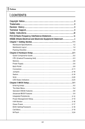
... 8-channel audio with jack sensing ■ Compliant with Azalia 1.0 Spec IDE ■ 1 IDE port by AMD® SB710 ■ Supports Ultra DMA 66/100/133 mode ■ Supports PIO, Bus Master operation mode SATA ■ 5 SATAII ports by AMD® SB710 ■ 1 E-SATA port by AMD® SB710 ■ Supports storage and data transfers at up to 3 Gb/s RAID ■ SATA 1~5 supports RAID 0/ 1/ 0+1 or JBOD mode by AMD® SB710 1-2 ▍ Getting Started Mainboard Specifications Processor Support ■ AMD® 64 bits PhenomTM...
... 8-channel audio with jack sensing ■ Compliant with Azalia 1.0 Spec IDE ■ 1 IDE port by AMD® SB710 ■ Supports Ultra DMA 66/100/133 mode ■ Supports PIO, Bus Master operation mode SATA ■ 5 SATAII ports by AMD® SB710 ■ 1 E-SATA port by AMD® SB710 ■ Supports storage and data transfers at up to 3 Gb/s RAID ■ SATA 1~5 supports RAID 0/ 1/ 0+1 or JBOD mode by AMD® SB710 1-2 ▍ Getting Started Mainboard Specifications Processor Support ■ AMD® 64 bits PhenomTM...
User Guide
Page 23
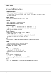
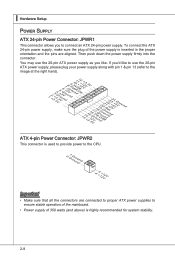
▍ Hardware Setup Power Supply ATX 24-pin Power Connector: JPWR1 This connector allows you like to use the 20-pin ATX power supply as you to ensure stable operation of the mainboard. • Power supply of the power supply is highly recommended for system stability. 2-8 Then push down the power supply firmly into the connector. If you'd like . To connect the ATX 24-pin power supply, make sure the plug of 350 watts (and above) is inserted in...
▍ Hardware Setup Power Supply ATX 24-pin Power Connector: JPWR1 This connector allows you like to use the 20-pin ATX power supply as you to ensure stable operation of the mainboard. • Power supply of the power supply is highly recommended for system stability. 2-8 Then push down the power supply firmly into the connector. If you'd like . To connect the ATX 24-pin power supply, make sure the plug of 350 watts (and above) is inserted in...
User Guide
Page 24
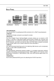
... monitor manual for more information.) ▶ USB Port The USB (Universal Serial Bus) port is for attaching USB devices such as keyboard, mouse, or other USB-compatible devices. ▶ HDMI Port The High-Definition Multimedia Interface (HDMI) is an all-digital audio/video interface capable of transmitting uncompressed streams. HDMI supports all TV format, including standard, enhanced, or high-definition video, plus multi-channel digital audio on a single cable. ▶ E-SATA Port The E-SATA (External-SATA) port is provided for attaching the E-SATA hard drive...
... monitor manual for more information.) ▶ USB Port The USB (Universal Serial Bus) port is for attaching USB devices such as keyboard, mouse, or other USB-compatible devices. ▶ HDMI Port The High-Definition Multimedia Interface (HDMI) is an all-digital audio/video interface capable of transmitting uncompressed streams. HDMI supports all TV format, including standard, enhanced, or high-definition video, plus multi-channel digital audio on a single cable. ▶ E-SATA Port The E-SATA (External-SATA) port is provided for attaching the E-SATA hard drive...
User Guide
Page 26
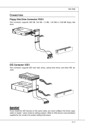
... install two IDE devices on the same cable, you must configure the drives separately to IDE device's documentation supplied by setting jumpers. Refer to master / slave mode by the vendors for jumper setting instructions. 2-11 Fl opMpySDI Kdkldkddfkkakfskkdskkdakaddfdddffdfkad-dkdffdldkddjadfdsdddjfdddffkadasdfdddffdfadasfsadfddsddadasdsaddsdafsddadsdddfdsadddfffaffsfsdasfdfffdf 5 D 1i s/k4"DFr il voeppCyonnect or 3 1/2" F l oppy D i sk D r i ve Connector 3 1/2" F l oppy D i sk D ri ve Connector IDE Connector: IDE1 This connector supports IDE hard disk drives, optical disk drives...
... install two IDE devices on the same cable, you must configure the drives separately to IDE device's documentation supplied by setting jumpers. Refer to master / slave mode by the vendors for jumper setting instructions. 2-11 Fl opMpySDI Kdkldkddfkkakfskkdskkdakaddfdddffdfkad-dkdffdldkddjadfdsdddjfdddffkadasdfdddffdfadasfsadfddsddadasdsaddsdafsddadsdddfdsadddfffaffsfsdasfdfffdf 5 D 1i s/k4"DFr il voeppCyonnect or 3 1/2" F l oppy D i sk D r i ve Connector 3 1/2" F l oppy D i sk D ri ve Connector IDE Connector: IDE1 This connector supports IDE hard disk drives, optical disk drives...
User Guide
Page 28
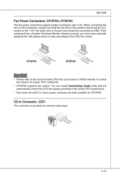
... Fan Power Connectors: CPUFAN, SYSFAN The fan power connectors support system cooling fan with speed sensor to take advantage of the CPU fan control. If the mainboard has a System Hardware Monitor chipset on-board, you must use a specially designed fan with +12V. When connecting the wire to the connectors, always note that will automatically control the CPU fan speed according to the actual CPU temperature. • Fan cooler set with 3 or 4 pins power connector are both available for CPUFAN. You can install Overclocking Center utility...
... Fan Power Connectors: CPUFAN, SYSFAN The fan power connectors support system cooling fan with speed sensor to take advantage of the CPU fan control. If the mainboard has a System Hardware Monitor chipset on-board, you must use a specially designed fan with +12V. When connecting the wire to the connectors, always note that will automatically control the CPU fan speed according to the actual CPU temperature. • Fan cooler set with 3 or 4 pins power connector are both available for CPUFAN. You can install Overclocking Center utility...
User Guide
Page 33
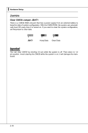
If you want to clear the system configuration, set the jumper to 1-2 pin position. Then return to clear data. 1 JBAT1 1 Keep Data 1 Clear Data Important You can automatically boot OS every time it will damage the mainboard. 2-18 Avoid clearing the CMOS while the system is a CMOS RAM onboard that has a power supply from an external battery to keep the data of system configuration. ▍ Hardware Setup Jumpers Clear CMOS Jumper: JBAT1 There is on . it is off. With the CMOS RAM, the system can clear CMOS by shorting 2-3 pin while the system is turned on ;
If you want to clear the system configuration, set the jumper to 1-2 pin position. Then return to clear data. 1 JBAT1 1 Keep Data 1 Clear Data Important You can automatically boot OS every time it will damage the mainboard. 2-18 Avoid clearing the CMOS while the system is a CMOS RAM onboard that has a power supply from an external battery to keep the data of system configuration. ▍ Hardware Setup Jumpers Clear CMOS Jumper: JBAT1 There is on . it is off. With the CMOS RAM, the system can clear CMOS by shorting 2-3 pin while the system is turned on ;
User Guide
Page 35
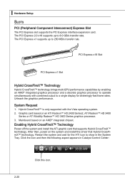
▍ Hardware Setup Slots PCI (Peripheral Component Interconnect) Express Slot The PCI Express slot supports the PCI Express interface expansion card. System Request 1. Mainboard based on the system and install the driver that supports Hybrid CrossFireX™ technology. After then, power on an AMD® integrated chipset. PCI Express x16 Slot PCI Express x1 Slot Hybrid CrossFireX™ Technology Hybrid CrossFireX™ technology brings multi-GPU performance capabilities by enabling an AMD® integrated graphics processor and a discrete graphics processor to operate ...
▍ Hardware Setup Slots PCI (Peripheral Component Interconnect) Express Slot The PCI Express slot supports the PCI Express interface expansion card. System Request 1. Mainboard based on the system and install the driver that supports Hybrid CrossFireX™ technology. After then, power on an AMD® integrated chipset. PCI Express x16 Slot PCI Express x1 Slot Hybrid CrossFireX™ Technology Hybrid CrossFireX™ technology brings multi-GPU performance capabilities by enabling an AMD® integrated graphics processor and a discrete graphics processor to operate ...
User Guide
Page 37
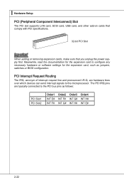
... Setup PCI (Peripheral Component Interconnect) Slot The PCI slot supports LAN card, SCSI card, USB card, and other add-on cards that comply with PCI specifications. 32-bit PCI Slot Important When adding or removing expansion cards, make sure that you unplug the power supply first. The PCI IRQ pins are hardware lines over which devices can send interrupt signals to the microprocessor. Meanwhile, read the documentation for the expansion card, such as follows: PCI Slot1 PCI...
... Setup PCI (Peripheral Component Interconnect) Slot The PCI slot supports LAN card, SCSI card, USB card, and other add-on cards that comply with PCI specifications. 32-bit PCI Slot Important When adding or removing expansion cards, make sure that you unplug the power supply first. The PCI IRQ pins are hardware lines over which devices can send interrupt signals to the microprocessor. Meanwhile, read the documentation for the expansion card, such as follows: PCI Slot1 PCI...
User Guide
Page 46
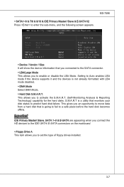
... to set the type of floppy drives installed. 3-7 Important IDE Primary Master/ Slave, SATA 1~5 & E-SATA are appearing when you connect the HD devices to the IDE/ SATA/ E-SATA connectors on the mainboard. ▶ Floppy Drive A This item allows you to a safe place before the hard disk becomes offline. This allows you to predict hard disk failure. S.M.A.R.T is a utility that monitors your disk status to activate the S.M.A.R.T. (Self-Monitoring Analysis & Reporting Technology) capability for the hard disks. Setting to enable or disable the LBA Mode...
... to set the type of floppy drives installed. 3-7 Important IDE Primary Master/ Slave, SATA 1~5 & E-SATA are appearing when you connect the HD devices to the IDE/ SATA/ E-SATA connectors on the mainboard. ▶ Floppy Drive A This item allows you to a safe place before the hard disk becomes offline. This allows you to predict hard disk failure. S.M.A.R.T is a utility that monitors your disk status to activate the S.M.A.R.T. (Self-Monitoring Analysis & Reporting Technology) capability for the hard disks. Setting to enable or disable the LBA Mode...
User Guide
Page 49
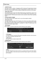
... that is used for the system. ▶ MPS Table Version This field allows you to read the CPU power consumption while idle. Enabling APIC mode will provide you should set to run in APIC mode. Not all processors support Enhanced Halt state (C1E). ▶ SVM Support This item is part of your primary graphics adapter. ▶ PCI Latency Timer This item controls how long each PCI device can...
... that is used for the system. ▶ MPS Table Version This field allows you to read the CPU power consumption while idle. Enabling APIC mode will provide you should set to run in APIC mode. Not all processors support Enhanced Halt state (C1E). ▶ SVM Support This item is part of your primary graphics adapter. ▶ PCI Latency Timer This item controls how long each PCI device can...
User Guide
Page 51
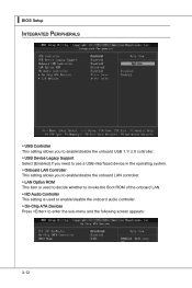
...; BIOS Setup Integrated Peripherals ▶ USB Controller This setting allows you to enable/disable the onboard USB 1.1/ 2.0 controller. ▶ USB Device Legacy Support Select [Enabled] if you need to use a USB-interfaced device in the operating system. ▶ Onboard LAN Controller This setting allows you to enable/disable the onboard LAN controller. ▶ LAN Option ROM This item is used to decide whether to invoke the Boot ROM of the onboard LAN. ▶ HD Audio Controller This setting is used to enable/disable the onboard audio controller. ▶ On-Chip ATA Devices Press to enter...
...; BIOS Setup Integrated Peripherals ▶ USB Controller This setting allows you to enable/disable the onboard USB 1.1/ 2.0 controller. ▶ USB Device Legacy Support Select [Enabled] if you need to use a USB-interfaced device in the operating system. ▶ Onboard LAN Controller This setting allows you to enable/disable the onboard LAN controller. ▶ LAN Option ROM This item is used to decide whether to invoke the Boot ROM of the onboard LAN. ▶ HD Audio Controller This setting is used to enable/disable the onboard audio controller. ▶ On-Chip ATA Devices Press to enter...

User Guide
Page 52
...] Enhanced Parallel Port [ECP] Extended Capability Port [ECP + EPP] Extended Capability Port + Enhanced Parallel Port [Bi-Directional] To operate the onboard parallel port as Standard Parallel Port only, choose [SPP]. MS-7596 ▶ PCI IDE BusMaster This item allows you to enable/ disable BIOS to used to select mode for reading/ writing to IDE drives. ▶ OnChip SATA Controller This item allows users to enable or disable the SATA controller. ▶ RAID Mode This item...
...] Enhanced Parallel Port [ECP] Extended Capability Port [ECP + EPP] Extended Capability Port + Enhanced Parallel Port [Bi-Directional] To operate the onboard parallel port as Standard Parallel Port only, choose [SPP]. MS-7596 ▶ PCI IDE BusMaster This item allows you to enable/ disable BIOS to used to select mode for reading/ writing to IDE drives. ▶ OnChip SATA Controller This item allows users to enable or disable the SATA controller. ▶ RAID Mode This item...
User Guide
Page 53
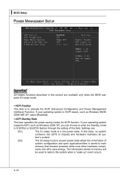
... BIOS supports S3 sleep mode. ▶ ACPI Function This item is to enter the Standby mode in S1(POS) or S3(STR) fashion through the setting of system configuration and open applications/files is saved to main memory that remains powered while most other hardware components turn off to restore the system when a "wake up" event occurs. 3-14 tem's context. [S3] The S3 sleep mode is a lower power...
... BIOS supports S3 sleep mode. ▶ ACPI Function This item is to enter the Standby mode in S1(POS) or S3(STR) fashion through the setting of system configuration and open applications/files is saved to main memory that remains powered while most other hardware components turn off to restore the system when a "wake up" event occurs. 3-14 tem's context. [S3] The S3 sleep mode is a lower power...

User Guide
Page 54
... sub-menu appears. ▶ Wake Up Event By Setting to [BIOS] activates the following fields, and use the following fields to set to [Enabled], the feature allows your system to be awakened from the power saving modes through any event on PCIE device. ▶ Resume By RTC Alarm The field is turned off button. [Suspend] When you press the power button, the computer enters suspend/ sleep mode, but...
... sub-menu appears. ▶ Wake Up Event By Setting to [BIOS] activates the following fields, and use the following fields to set to [Enabled], the feature allows your system to be awakened from the power saving modes through any event on PCIE device. ▶ Resume By RTC Alarm The field is turned off button. [Suspend] When you press the power button, the computer enters suspend/ sleep mode, but...

User Guide
Page 55
... mainboard provides the Smart Fan function which can enable a fan target value here. To clear the warning message, set the field to keep it with in a specific range. You can control the CPU fan speed automatically depending on the current temperature to [Reset]. The setting of recording the chassis intrusion status and issuing a warning message if the chassis is once opened. ▍ BIOS Setup H/W Monitor ▶ Chassis Intrusion The field enables or disables...
... mainboard provides the Smart Fan function which can enable a fan target value here. To clear the warning message, set the field to keep it with in a specific range. You can control the CPU fan speed automatically depending on the current temperature to [Reset]. The setting of recording the chassis intrusion status and issuing a warning message if the chassis is once opened. ▍ BIOS Setup H/W Monitor ▶ Chassis Intrusion The field enables or disables...
User Guide
Page 65
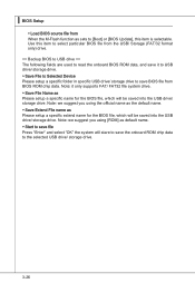
... Selected Device Please setup a specific folder in specific USB drive/ storage drive to [Boot] or [BIOS Update], this item to select particular BIOS file from the USB/ Storage (FAT/32 format only) drive. == Backup BIOS to USB drive == The following fields are used to read the onboard BIOS ROM data, and save it only supports FAT/ FAT32 file system drive. ▶ Save File Name as sets to save the onboard ROM chip data to the selected USB drive/ storage drive. 3-26 ▍ BIOS Setup ▶ Load BIOS source file from BIOS ROM chip...
... Selected Device Please setup a specific folder in specific USB drive/ storage drive to [Boot] or [BIOS Update], this item to select particular BIOS file from the USB/ Storage (FAT/32 format only) drive. == Backup BIOS to USB drive == The following fields are used to read the onboard BIOS ROM data, and save it only supports FAT/ FAT32 file system drive. ▶ Save File Name as sets to save the onboard ROM chip data to the selected USB drive/ storage drive. 3-26 ▍ BIOS Setup ▶ Load BIOS source file from BIOS ROM chip...

User Guide
Page 97
...: \\ChipSet\AMD\XP\SBDrv\RAID7xx - Insert the floppy that you complete the RAID BIOS setup, boot from the floppy again after selecting the location to make a SATA RAID driver for RAID controller is formatted, and Windows setup starts copying files. Note: for Windows Vista, you can copy the files to a medium (floppy/ CD/ DVD or USB) Important Please follow the instruction below to install Vista click on the Setup screen. • Copy all the contents in the floppy drive...
...: \\ChipSet\AMD\XP\SBDrv\RAID7xx - Insert the floppy that you complete the RAID BIOS setup, boot from the floppy again after selecting the location to make a SATA RAID driver for RAID controller is formatted, and Windows setup starts copying files. Note: for Windows Vista, you can copy the files to a medium (floppy/ CD/ DVD or USB) Important Please follow the instruction below to install Vista click on the Setup screen. • Copy all the contents in the floppy drive...

User Guide
Page 98
The AMD chipset drivers include RAID Driver. 4. Under the Driver tab, click on AMD chipset drivers by your need. Insert the MSI DVD into the DVD-ROM drive. 2. The driver will appear. 3. B-9 The DVD will auto-run and the setup screen will be automatically installed. MS-7596 Installing the RAID Driver Under Windows (for Non-bootable RAID Array) 1.
The AMD chipset drivers include RAID Driver. 4. Under the Driver tab, click on AMD chipset drivers by your need. Insert the MSI DVD into the DVD-ROM drive. 2. The driver will appear. 3. B-9 The DVD will auto-run and the setup screen will be automatically installed. MS-7596 Installing the RAID Driver Under Windows (for Non-bootable RAID Array) 1.


