
User Guide
Page 2
... equipment in a residential area is operated in a commercial environment. power cord, if any, must be required to correct the interference at his own expense. Micro-Star International MS-7005 ii Operation of the FCC rules. Manual Rev: 2.0 Release Date: February 2004 FCC-B Radio Frequency Interference Statement This equipment has been tested and found...
... equipment in a residential area is operated in a commercial environment. power cord, if any, must be required to correct the interference at his own expense. Micro-Star International MS-7005 ii Operation of the FCC rules. Manual Rev: 2.0 Release Date: February 2004 FCC-B Radio Frequency Interference Statement This equipment has been tested and found...

User Guide
Page 7
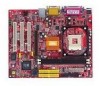
With all these special designs, the 651M-V Series delivers a high performance and professional desktop platform solution. 1-1 Getting Started Getting Started Thank you for high-speed data transmission. The 651M-V Series is based on SiS® 651 (702 pin BGA) & SiS® 962L MuTIOL Media I/O (371 BGA) chipsets and provides 6 USB 2.0 ports for purchasing 651M-V Series (MS-7005) v2.X Micro ATX mainboard.
With all these special designs, the 651M-V Series delivers a high performance and professional desktop platform solution. 1-1 Getting Started Getting Started Thank you for high-speed data transmission. The 651M-V Series is based on SiS® 651 (702 pin BGA) & SiS® 962L MuTIOL Media I/O (371 BGA) chipsets and provides 6 USB 2.0 ports for purchasing 651M-V Series (MS-7005) v2.X Micro ATX mainboard.
User Guide
Page 8
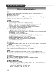
... PC2001 compliance - Integrated multi-threaded I /O (371BGA) - h Hyper-Threading CPU. (For the latest information about CPU, please visit http://www.msi.com.tw/program/ products/mainboard/mbd/pro_mbd_cpu_support.php) Chipset h SiS 651 (702 pin BGA) - Integrated MuTIOL connect to four IDE devices. h Support... Main Memory h Supports two memory banks using two 184-pin unbuffered DDR 200/266/333 DIMMs. h Supports up to 3.06GHz. MS-7005 Micro ATX Mainboard Mainboard Specifications CPU h Socket 478 for P4 processors (Northwood/Prescott) at 400 MHz/533 MHz h Supports up to 2GB memory...
... PC2001 compliance - Integrated multi-threaded I /O (371BGA) - h Hyper-Threading CPU. (For the latest information about CPU, please visit http://www.msi.com.tw/program/ products/mainboard/mbd/pro_mbd_cpu_support.php) Chipset h SiS 651 (702 pin BGA) - Integrated MuTIOL connect to four IDE devices. h Support... Main Memory h Supports two memory banks using two 184-pin unbuffered DDR 200/266/333 DIMMs. h Supports up to 3.06GHz. MS-7005 Micro ATX Mainboard Mainboard Specifications CPU h Socket 478 for P4 processors (Northwood/Prescott) at 400 MHz/533 MHz h Supports up to 2GB memory...
User Guide
Page 10
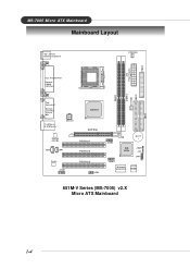
AT X Power Supply FDD1 DDR 1 DDR 2 S Y S FA N 1 IDE 2 IDE 1 MS-7005 Micro ATX Mainboard Mainboard Layout Top : mouse Bottom: keyboard CPUFAN1 Top : Parallel Port Bottom: COM A VGA Port Top : Game port Bottom: Line-Out Line-In Mic T: LAN jack B: USB ports AT X 1 2 V SiS 651 AGP Slot Realtek 8201BL PCI Slot 1 JCD1 JSP1 PCI Slot 2 Codec JAUD1 PCI Slot 3 JFP2 JUSB2 BATT + SiS 962L J BAT 1 JCI1 JFP1 JUSB1 Winbond W83697HF BIOS 651M-V Series (MS-7005) v2.X Micro ATX Mainboard 1-4
AT X Power Supply FDD1 DDR 1 DDR 2 S Y S FA N 1 IDE 2 IDE 1 MS-7005 Micro ATX Mainboard Mainboard Layout Top : mouse Bottom: keyboard CPUFAN1 Top : Parallel Port Bottom: COM A VGA Port Top : Game port Bottom: Line-Out Line-In Mic T: LAN jack B: USB ports AT X 1 2 V SiS 651 AGP Slot Realtek 8201BL PCI Slot 1 JCD1 JSP1 PCI Slot 2 Codec JAUD1 PCI Slot 3 JFP2 JUSB2 BATT + SiS 962L J BAT 1 JCI1 JFP1 JUSB1 Winbond W83697HF BIOS 651M-V Series (MS-7005) v2.X Micro ATX Mainboard 1-4

User Guide
Page 14
... is being closed, always close the lever. Pull the lever sideways away from the socket. Sliding Plate 90 degree 3. The gold arrow should be seen. MS-7005 Micro ATX Mainboard CPU Installation Procedures for the gold arrow. If the CPU is properly and completely embedded into the socket. Make sure to raise the lever...
... is being closed, always close the lever. Pull the lever sideways away from the socket. Sliding Plate 90 degree 3. The gold arrow should be seen. MS-7005 Micro ATX Mainboard CPU Installation Procedures for the gold arrow. If the CPU is properly and completely embedded into the socket. Make sure to raise the lever...

User Guide
Page 16
Connect the fan power cable from the mounted fan to the 3-pin fan power connector on the board. MS-7005 Micro ATX Mainboard 5. fan power cable NOTES 2-6
Connect the fan power cable from the mounted fan to the 3-pin fan power connector on the board. MS-7005 Micro ATX Mainboard 5. fan power cable NOTES 2-6
User Guide
Page 18
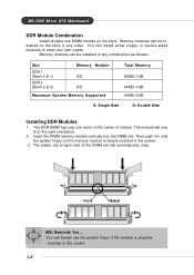
... the slots. The module will automatically close. Volt Notch MSI Reminds You... or double-sided modules to meet your own needs. Memory modules can be installed on the memory module is properly inserted in the socket. 2-8 You can install either single- MS-7005 Micro ATX Mainboard DDR Module Combination Install at each side of module...
... the slots. The module will automatically close. Volt Notch MSI Reminds You... or double-sided modules to meet your own needs. Memory modules can be installed on the memory module is properly inserted in the socket. 2-8 You can install either single- MS-7005 Micro ATX Mainboard DDR Module Combination Install at each side of module...

User Guide
Page 20
... Female) Pin Definition PIN SIGNAL DESCRIPTION 1 Keyboard DATA Keyboard DATA 2 NC No connection 3 GND Ground 4 VCC +5V 5 Keyboard Clock Keyboard clock 6 NC No connection 2-10 MS-7005 Micro ATX Mainboard Back Panel The back panel provides the following connectors: Mouse Parallel Midi/Joystick LAN Keyboard COMA VGA Port L-out L-in MIC USB Ports Mouse...
... Female) Pin Definition PIN SIGNAL DESCRIPTION 1 Keyboard DATA Keyboard DATA 2 NC No connection 3 GND Ground 4 VCC +5V 5 Keyboard Clock Keyboard clock 6 NC No connection 2-10 MS-7005 Micro ATX Mainboard Back Panel The back panel provides the following connectors: Mouse Parallel Midi/Joystick LAN Keyboard COMA VGA Port L-out L-in MIC USB Ports Mouse...
User Guide
Page 22
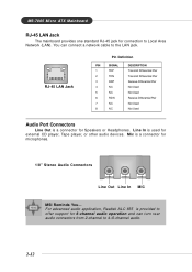
MS-7005 Micro ATX Mainboard RJ-45 LAN Jack The mainboard provides one standard RJ-45 jack for external CD player, Tape player, or other audio devices. You can ... (LAN). For advanced audio application, Realtek ALC 655 is used for connection to offer support for microphones. 1/8" Stereo Audio Connectors Line Out Line In MIC MSI Reminds You... Mic is a connector for Speakers or Headphones. RJ-45 LAN Jack Pin Definition PIN SIGNAL 1 TDP 2 TDN 3 RDP 4 NC 5 NC 6 RDN 7 NC 8 NC...
MS-7005 Micro ATX Mainboard RJ-45 LAN Jack The mainboard provides one standard RJ-45 jack for external CD player, Tape player, or other audio devices. You can ... (LAN). For advanced audio application, Realtek ALC 655 is used for connection to offer support for microphones. 1/8" Stereo Audio Connectors Line Out Line In MIC MSI Reminds You... Mic is a connector for Speakers or Headphones. RJ-45 LAN Jack Pin Definition PIN SIGNAL 1 TDP 2 TDN 3 RDP 4 NC 5 NC 6 RDN 7 NC 8 NC...
User Guide
Page 24
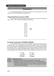
..., 1.44M and 2.88M floppy disk types. GND +12V SENSOR CPUFAN1 GND +12V SENSOR SYSFAN1 MSI Reminds You... 1. CPUFAN1 supports the fan control. They support three-pin head connector. Always consult the vendors for proper CPU cooling fan. 2. MS-7005 Micro ATX Mainboard Connectors The mainboard provides connectors to connect to the actual CPU temperature. 2-14...
..., 1.44M and 2.88M floppy disk types. GND +12V SENSOR CPUFAN1 GND +12V SENSOR SYSFAN1 MSI Reminds You... 1. CPUFAN1 supports the fan control. They support three-pin head connector. Always consult the vendors for proper CPU cooling fan. 2. MS-7005 Micro ATX Mainboard Connectors The mainboard provides connectors to connect to the actual CPU temperature. 2-14...
User Guide
Page 26
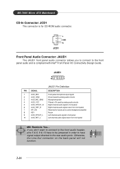
... Filtered +5V used by analog audio circuits 5 AUD_FPOUT_R Right channel audio signal to front panel 6 AUD_RET_R Right channel audio signal return from front panel MSI Reminds You... MS-7005 Micro ATX Mainboard CD-In Connector: JCD1 The connector is compliant with Intel® Front Panel I/O Connectivity Design Guide. If you to connect to the rear...
... Filtered +5V used by analog audio circuits 5 AUD_FPOUT_R Right channel audio signal to front panel 6 AUD_RET_R Right channel audio signal return from front panel MSI Reminds You... MS-7005 Micro ATX Mainboard CD-In Connector: JCD1 The connector is compliant with Intel® Front Panel I/O Connectivity Design Guide. If you to connect to the rear...
User Guide
Page 28
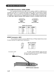
... to JSP1 The JSP1 supports SPDIF output only and can be connected to an external SPDIF Bracket for digital audio transmission. 2-18 SPDIF Bracket (Optional) MS-7005 Micro ATX Mainboard Front USB Connectors: JUSB1/JUSB2 The mainboard provides two USB 2.0 pin headers JUSB1 & JUSB2 that are compliant with Intel® I/O Connectivity Design Guide...
... to JSP1 The JSP1 supports SPDIF output only and can be connected to an external SPDIF Bracket for digital audio transmission. 2-18 SPDIF Bracket (Optional) MS-7005 Micro ATX Mainboard Front USB Connectors: JUSB1/JUSB2 The mainboard provides two USB 2.0 pin headers JUSB1 & JUSB2 that are compliant with Intel® I/O Connectivity Design Guide...
User Guide
Page 30
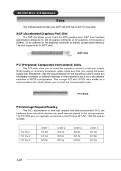
... to the microprocessor. The slot supports 4x/2x AGP card. The orange PCI slot (PCI5) also works as jumpers, switches or BIOS configuration. MS-7005 Micro ATX Mainboard Slots The motherboard provides one AGP slot and five 32-bit PCI bus slots. When adding or removing expansion cards, make any necessary hardware or software settings...
... to the microprocessor. The slot supports 4x/2x AGP card. The orange PCI slot (PCI5) also works as jumpers, switches or BIOS configuration. MS-7005 Micro ATX Mainboard Slots The motherboard provides one AGP slot and five 32-bit PCI bus slots. When adding or removing expansion cards, make any necessary hardware or software settings...

User Guide
Page 32
... make changes General help, only for the highlighted item. Press to the main menu, just press . You may also restart the system by simply pressing . MS-7005 Micro ATX Mainboard Entering Setup Power on -line description of the highlighted setup function is the Main Menu. Sub-Menu If you want to return to exit...
... make changes General help, only for the highlighted item. Press to the main menu, just press . You may also restart the system by simply pressing . MS-7005 Micro ATX Mainboard Entering Setup Power on -line description of the highlighted setup function is the Main Menu. Sub-Menu If you want to return to exit...

User Guide
Page 34
Set User Password Use this menu to set Supervisor Password. Set Supervisor Password Use this menu to set User Password. Exit Without Saving Abandon all changes and exit setup. 3-4 Save & Exit Setup Save changes to load factory default settings into the BIOS for stable system performance operations. MS-7005 Micro ATX Mainboard Load Optimized Defaults Use this menu to CMOS and exit setup.
Set User Password Use this menu to set Supervisor Password. Set Supervisor Password Use this menu to set User Password. Exit Without Saving Abandon all changes and exit setup. 3-4 Save & Exit Setup Save changes to load factory default settings into the BIOS for stable system performance operations. MS-7005 Micro ATX Mainboard Load Optimized Defaults Use this menu to CMOS and exit setup.

User Guide
Page 36
Base/Extended/Total Memory The three items show the memory status of the system. MS-7005 Micro ATX Mainboard Drive A/B This item allows you to set the Floppy 3 Mode. Available options: [None], [360K, 5.25 in.], [1.2M, 5.25 in.], [720K, 3.5 in.], [1.44M, 3.5 in.], [2.88M, 3.5 ...
Base/Extended/Total Memory The three items show the memory status of the system. MS-7005 Micro ATX Mainboard Drive A/B This item allows you to set the Floppy 3 Mode. Available options: [None], [360K, 5.25 in.], [1.2M, 5.25 in.], [720K, 3.5 in.], [1.44M, 3.5 in.], [2.88M, 3.5 ...
User Guide
Page 38
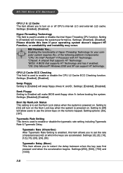
...[8], [10], [12], [15], [20], [24], [30]. Setting to [Off] will make BIOS seek floppy drive A: before booting the system. MS-7005 Micro ATX Mainboard CPU L1 & L2 Cache The item allows you to select the delay between when the key was first pressed and when the acceleration begins.... Settings: [Enabled], [Disabled]. Hyper-Threading Technology This field is powered on . Settings: [Enabled], [Disabled]. MSI Reminds You... Settings: [Enabled], [Disabled]. Seek Floppy Setting to Enabled will allow users to use the arrow keys on the Num Lock...
...[8], [10], [12], [15], [20], [24], [30]. Setting to [Off] will make BIOS seek floppy drive A: before booting the system. MS-7005 Micro ATX Mainboard CPU L1 & L2 Cache The item allows you to select the delay between when the key was first pressed and when the acceleration begins.... Settings: [Enabled], [Disabled]. Hyper-Threading Technology This field is powered on . Settings: [Enabled], [Disabled]. MSI Reminds You... Settings: [Enabled], [Disabled]. Seek Floppy Setting to Enabled will allow users to use the arrow keys on the Num Lock...

User Guide
Page 40
... SDRAM signal controller to support loose layouts or slower memory. Selecting [1T] makes SDRAM signal controller run at 2T rate. 1T is faster than 2T. MS-7005 Micro ATX Mainboard Advanced Chipset Features MSI Reminds You...
... SDRAM signal controller to support loose layouts or slower memory. Selecting [1T] makes SDRAM signal controller run at 2T rate. 1T is faster than 2T. MS-7005 Micro ATX Mainboard Advanced Chipset Features MSI Reminds You...
User Guide
Page 42
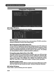
Settings: [Auto], [Disabled]. Modes 0 through 4 provide successively increased performance. IDE DMA transfer access Setting to enable BIOS support. MS-7005 Micro ATX Mainboard Integrated Peripherals SiS OnChip IDE Device Press and the following sub-menu appears: 3-12 In [Auto] mode, the system automatically determines the best mode ...
Settings: [Auto], [Disabled]. Modes 0 through 4 provide successively increased performance. IDE DMA transfer access Setting to enable BIOS support. MS-7005 Micro ATX Mainboard Integrated Peripherals SiS OnChip IDE Device Press and the following sub-menu appears: 3-12 In [Auto] mode, the system automatically determines the best mode ...
User Guide
Page 44
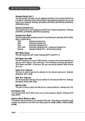
... your primary graphics adapter. Settings: [5], [10]. Settings: [PCI Slot], [AGP]. Settings: [EPP1.9], [EPP1.7]. After selecting it, the following message will appear: "ECP Mode Use DMA." MS-7005 Micro ATX Mainboard Onboard Serial Port 1 The item specify the base I/O port address and IRQ for the onboard Midi Port. Selecting [Auto] allows BIOS to the VGA...
... your primary graphics adapter. Settings: [5], [10]. Settings: [PCI Slot], [AGP]. Settings: [EPP1.9], [EPP1.7]. After selecting it, the following message will appear: "ECP Mode Use DMA." MS-7005 Micro ATX Mainboard Onboard Serial Port 1 The item specify the base I/O port address and IRQ for the onboard Midi Port. Selecting [Auto] allows BIOS to the VGA...


