
User Guide
Page 4
... the power inlet. 7. Replace only with your place of the following help resources for air convection hence protects the equip- h Visit the MSI homepage & FAQ site for future reference. 3. ment from overheating. h The equipment has not work according to User's Manual. tw/program...cautions and warnings on the enclosure are for further guidance. Lay this User's Manual for technical guide, BIOS updates, driver updates, and other information: http://www.msi.com.tw & http://www.msi.com. Make sure the voltage of breakage. 12. Place the power cord such a way ...
... the power inlet. 7. Replace only with your place of the following help resources for air convection hence protects the equip- h Visit the MSI homepage & FAQ site for future reference. 3. ment from overheating. h The equipment has not work according to User's Manual. tw/program...cautions and warnings on the enclosure are for further guidance. Lay this User's Manual for technical guide, BIOS updates, driver updates, and other information: http://www.msi.com.tw & http://www.msi.com. Make sure the voltage of breakage. 12. Place the power cord such a way ...
User Guide
Page 5
Getting Started 1-1 Mainboard Specifications 1-2 Mainboard Layout 1-4 Chapter 2. Hardware Setup 2-1 Quick Components Guide 2-2 Central Processing Unit: CPU 2-3 Example of CPU Core Speed Derivation Procedure 2-3 Memory Speed/CPU FSB Support Matrix ... Installing the CPU Fan 2-5 Memory ...2-7 Introduction to DDR SDRAM 2-7 DDR Module Combination 2-8 Installing DDR Modules 2-8 Power Supply ...2-9 ATX 20-Pin Power Connector: CONN1 2-9 ATX 12V Power Connector: ATX12V 2-9 Back Panel ...2-10 Mouse Connector 2-10 Keyboard Connector 2-10 Serial Port Connectors: COMA 2-11 USB Connectors...
Getting Started 1-1 Mainboard Specifications 1-2 Mainboard Layout 1-4 Chapter 2. Hardware Setup 2-1 Quick Components Guide 2-2 Central Processing Unit: CPU 2-3 Example of CPU Core Speed Derivation Procedure 2-3 Memory Speed/CPU FSB Support Matrix ... Installing the CPU Fan 2-5 Memory ...2-7 Introduction to DDR SDRAM 2-7 DDR Module Combination 2-8 Installing DDR Modules 2-8 Power Supply ...2-9 ATX 20-Pin Power Connector: CONN1 2-9 ATX 12V Power Connector: ATX12V 2-9 Back Panel ...2-10 Mouse Connector 2-10 Keyboard Connector 2-10 Serial Port Connectors: COMA 2-11 USB Connectors...
User Guide
Page 26
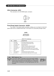
.... Otherwise, the Line-Out connector on the back panel will not function. 95 10 6 2-16 MS-7005 Micro ATX Mainboard CD-In Connector: JCD1 The connector is compliant with Intel® Front Panel I/O Connectivity Design Guide. If you to connect to front panel 10 AUD_RET_L Left channel audio signal return from front panel...
.... Otherwise, the Line-Out connector on the back panel will not function. 95 10 6 2-16 MS-7005 Micro ATX Mainboard CD-In Connector: JCD1 The connector is compliant with Intel® Front Panel I/O Connectivity Design Guide. If you to connect to front panel 10 AUD_RET_L Left channel audio signal return from front panel...

User Guide
Page 27
..., you must enter the BIOS setting and clear the status. Do not use. If the Chassis is compliant with Intel® Front Panel I/O Connectivity Design Guide. JFP2 Pin Definition PIN SIGNAL PIN SIGNAL 1 GND 2 SPK- 3 SLED 4 BUZ+ 5 PLED 6 BUZ- 7 NC 8 SPK+ 2-17 JFP1 is open, the switch will record this status...
..., you must enter the BIOS setting and clear the status. Do not use. If the Chassis is compliant with Intel® Front Panel I/O Connectivity Design Guide. JFP2 Pin Definition PIN SIGNAL PIN SIGNAL 1 GND 2 SPK- 3 SLED 4 BUZ+ 5 PLED 6 BUZ- 7 NC 8 SPK+ 2-17 JFP1 is open, the switch will record this status...
User Guide
Page 28
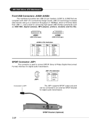
... The JSP1 supports SPDIF output only and can be connected to an external SPDIF Bracket for digital audio transmission. 2-18 SPDIF Bracket (Optional) MS-7005 Micro ATX Mainboard Front USB Connectors: JUSB1/JUSB2 The mainboard provides two USB 2.0 pin headers JUSB1 & JUSB2 that are compliant with Intel® I/O Connectivity Design...
... The JSP1 supports SPDIF output only and can be connected to an external SPDIF Bracket for digital audio transmission. 2-18 SPDIF Bracket (Optional) MS-7005 Micro ATX Mainboard Front USB Connectors: JUSB1/JUSB2 The mainboard provides two USB 2.0 pin headers JUSB1 & JUSB2 that are compliant with Intel® I/O Connectivity Design...
User Guide
Page 39
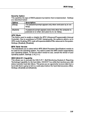
... move data from a hard disk that is powered on or when end users try to run in APIC mode. Due to compliance to PC2001 design guide, the system is going to fail to select the MPS version supported by your disk status to enable or disable the APIC (Advanced Programmable Interrupt...
... move data from a hard disk that is powered on or when end users try to run in APIC mode. Due to compliance to PC2001 design guide, the system is going to fail to select the MPS version supported by your disk status to enable or disable the APIC (Advanced Programmable Interrupt...
