Getting Started EN
Page 15
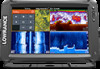
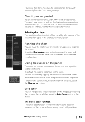
...settings dialog. Using the cursor on the panel The cursor can navigate to the unit's Operator manual. * Optional chart items. You turn the optional chart items on/off individually from the panel, select the Clear cursor option. Chart types supported Insight (Lowrance), Navionics, and C-MAP charts are supported.... Selecting chart type You specify the chart type in the Chart panel by tapping the desired location on the screen. Select the Clear cursor menu option to the vessel position. Charts | ELITE Ti Getting...
...settings dialog. Using the cursor on the panel The cursor can navigate to the unit's Operator manual. * Optional chart items. You turn the optional chart items on/off individually from the panel, select the Clear cursor option. Chart types supported Insight (Lowrance), Navionics, and C-MAP charts are supported.... Selecting chart type You specify the chart type in the Chart panel by tapping the desired location on the screen. Select the Clear cursor menu option to the vessel position. Charts | ELITE Ti Getting...
Getting Started EN
Page 27
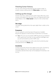
... The unit supports several transducer frequencies. If you will not be displayed if Sensitivity is active, some options on the screen. Too much detail clutters the screen. To resume normal scrolling, select the Clear cursor menu option. Decreasing Sensitivity displays less. Setting up the image. Sonar | ELITE Ti Getting Started 27 Available frequencies depend on the transducer model that is...
... The unit supports several transducer frequencies. If you will not be displayed if Sensitivity is active, some options on the screen. Too much detail clutters the screen. To resume normal scrolling, select the Clear cursor menu option. Decreasing Sensitivity displays less. Setting up the image. Sonar | ELITE Ti Getting Started 27 Available frequencies depend on the transducer model that is...
Installation Manual EN
Page 3
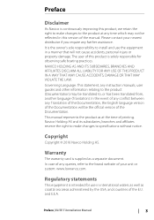
...instruction manuals, user guides and other information relating to the product (Documentation) may not be translated to, or has been translated from, another language (Translation). Warranty The warranty card is supplied as coastal sea areas administered by the USA, and countries of printing. and E.E.A. Please contact your unit or system: www.lowrance...to the product at the time of the E.U. Preface | ELITE Ti Installation Manual 3 NAVICO HOLDING AS AND ITS SUBSIDIARIES, BRANCHES AND AFFILIATES DISCLAIM ALL LIABILITY FOR ANY USE OF THIS PRODUCT IN A WAY THAT MAY CAUSE ACCIDENTS, ...
...instruction manuals, user guides and other information relating to the product (Documentation) may not be translated to, or has been translated from, another language (Translation). Warranty The warranty card is supplied as coastal sea areas administered by the USA, and countries of printing. and E.E.A. Please contact your unit or system: www.lowrance...to the product at the time of the E.U. Preface | ELITE Ti Installation Manual 3 NAVICO HOLDING AS AND ITS SUBSIDIARIES, BRANCHES AND AFFILIATES DISCLAIM ALL LIABILITY FOR ANY USE OF THIS PRODUCT IN A WAY THAT MAY CAUSE ACCIDENTS, ...

Installation Manual EN
Page 4
... with the instructions, may cause harmful interference to the following two conditions: (1) this device may cause undesired operation of the device. Warning The user is no guarantee that may not cause harmful interference, and (2) this device must accept any changes or modifications not expressly approved by turning the equipment off 4 Preface | ELITE Ti Installation Manual If this...
... with the instructions, may cause harmful interference to the following two conditions: (1) this device may cause undesired operation of the device. Warning The user is no guarantee that may not cause harmful interference, and (2) this device must accept any changes or modifications not expressly approved by turning the equipment off 4 Preface | ELITE Ti Installation Manual If this...
Installation Manual EN
Page 9
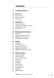
... transducer 25 Adjusting the transducer 26 Wiring 26 Guidelines 27 Power connection 27 Transducer connection 28 NMEA 2000 backbone 30 NMEA 0183 device connection 32 Software Setup 32 First time startup 32 Time and Date 33 Data source selection 35 Device list 35 Diagnostics 37 Damping 37 Sonar setup 39 StructureScan 39 Autopilot setup 39 Fuel setup 42 Wireless setup Contents | ELITE Ti Installation Manual...
... transducer 25 Adjusting the transducer 26 Wiring 26 Guidelines 27 Power connection 27 Transducer connection 28 NMEA 2000 backbone 30 NMEA 0183 device connection 32 Software Setup 32 First time startup 32 Time and Date 33 Data source selection 35 Device list 35 Diagnostics 37 Damping 37 Sonar setup 39 StructureScan 39 Autopilot setup 39 Fuel setup 42 Wireless setup Contents | ELITE Ti Installation Manual...
Installation Manual EN
Page 11
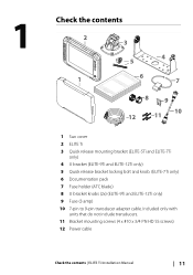
... mounting bracket (ELITE-5Ti and ELITE-7Ti only) 4 U bracket (ELITE-9Ti and ELITE-12Ti only) 5 Quick release bracket locking bolt and knob. (ELITE-7Ti only) 6 Documentation pack 7 Fuse holder (ATC blade) 8 U bracket knobs (2x) (ELITE-9Ti and ELITE-12Ti only) 9 Fuse (3 amp) 10 7-pin to 9-pin transducer adapter cable. Included only with units that do not include transducers. 11 Bracket mounting screws (4 x #10 x 3/4 PN HD SS screws) 12 Power cable Check the contents | ELITE Ti Installation Manual...
... mounting bracket (ELITE-5Ti and ELITE-7Ti only) 4 U bracket (ELITE-9Ti and ELITE-12Ti only) 5 Quick release bracket locking bolt and knob. (ELITE-7Ti only) 6 Documentation pack 7 Fuse holder (ATC blade) 8 U bracket knobs (2x) (ELITE-9Ti and ELITE-12Ti only) 9 Fuse (3 amp) 10 7-pin to 9-pin transducer adapter cable. Included only with units that do not include transducers. 11 Bracket mounting screws (4 x #10 x 3/4 PN HD SS screws) 12 Power cable Check the contents | ELITE Ti Installation Manual...
Installation Manual EN
Page 15
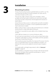
... boat builder, or marine electronics installer. Choose a location that will not expose the unit to conditions that any part where it can be used as a hand hold, where it might be submerged, or where it is possible to route cables to "Dimensional drawings" on page 62. The mounting location may affect the internal GPS receiver. refer to...
... boat builder, or marine electronics installer. Choose a location that will not expose the unit to conditions that any part where it can be used as a hand hold, where it might be submerged, or where it is possible to route cables to "Dimensional drawings" on page 62. The mounting location may affect the internal GPS receiver. refer to...
Installation Manual EN
Page 25
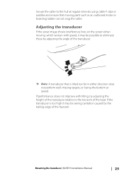
...targets, or losing the bottom at regular intervals using cable P clips or saddles and ensure that is too high it may be possible to eliminate these by the trailing edge of the transom. If the transducer is tilted too far in either direction does ...angle of the transducer. Ú Note: A transducer that moving parts such as an outboard motor or boarding ladder cannot snag the cable. Mounting the transducer | ELITE Ti Installation Manual 25 Secure the cable to the transom of the boat. Adjusting the transducer If the sonar image shows interference lines on the screen when moving, which...
...targets, or losing the bottom at regular intervals using cable P clips or saddles and ensure that is too high it may be possible to eliminate these by the trailing edge of the transom. If the transducer is tilted too far in either direction does ...angle of the transducer. Ú Note: A transducer that moving parts such as an outboard motor or boarding ladder cannot snag the cable. Mounting the transducer | ELITE Ti Installation Manual 25 Secure the cable to the transom of the boat. Adjusting the transducer If the sonar image shows interference lines on the screen when moving, which...
Installation Manual EN
Page 26
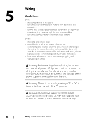
...carrying cables or high frequency signal cables. • run cables so they interfere with mechanical systems Do this: • make drip and service loops • use with 24 V DC systems. Warning: The positive supply wire (red) should be sure to turn electrical power off...power supply is not suited for use cable-tie on during the installation, fire, electrical shock, or other serious injury may occur. Extending cables should always be connected to (+) DC with the supplied fuse or a circuit breaker (closest available to fuse rating). 26 Wiring | ELITE Ti Installation Manual 5 Wiring ...
...carrying cables or high frequency signal cables. • run cables so they interfere with mechanical systems Do this: • make drip and service loops • use with 24 V DC systems. Warning: The positive supply wire (red) should be sure to turn electrical power off...power supply is not suited for use cable-tie on during the installation, fire, electrical shock, or other serious injury may occur. Extending cables should always be connected to (+) DC with the supplied fuse or a circuit breaker (closest available to fuse rating). 26 Wiring | ELITE Ti Installation Manual 5 Wiring ...
Installation Manual EN
Page 27
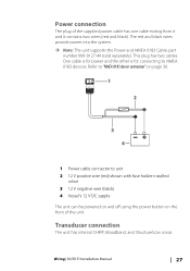
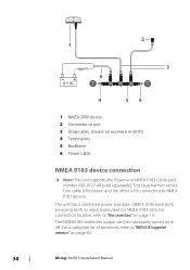
... has two cables. Wiring | ELITE Ti Installation Manual 27 The red and black wires provide power into the system. Ú Note: The unit supports the Power and NMEA 0183 Cable, part number 000-0127-49 (sold separately). Refer to "NMEA 0183 device connection" on page 30. 1 2 3 4 _+ 1 Power cable connector to NMEA 0183 devices. Transducer connection The unit has internal CHIRP, Broadband, and StructureScan sonar. Power connection The...
... has two cables. Wiring | ELITE Ti Installation Manual 27 The red and black wires provide power into the system. Ú Note: The unit supports the Power and NMEA 0183 Cable, part number 000-0127-49 (sold separately). Refer to "NMEA 0183 device connection" on page 30. 1 2 3 4 _+ 1 Power cable connector to NMEA 0183 devices. Transducer connection The unit has internal CHIRP, Broadband, and StructureScan sonar. Power connection The...
Installation Manual EN
Page 28
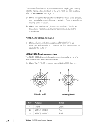
... back of data from various sources. Ú Note: The ELITE-5Ti does not have a NMEA 2000 data port. 1 5 1 5 2 4 4 2 3 Unit socket (male) 3 Cable plug (female) Key Purpose 1 Shield 2 NET-S (+12 VDC) 3 NET-C (- 12 VDC) Color Drain Red Black 28 Wiring | ELITE Ti Installation Manual This section does not apply to the transducer cable is keyed, and can be inserted in one orientation...
... back of data from various sources. Ú Note: The ELITE-5Ti does not have a NMEA 2000 data port. 1 5 1 5 2 4 4 2 3 Unit socket (male) 3 Cable plug (female) Key Purpose 1 Shield 2 NET-S (+12 VDC) 3 NET-C (- 12 VDC) Color Drain Red Black 28 Wiring | ELITE Ti Installation Manual This section does not apply to the transducer cable is keyed, and can be inserted in one orientation...
Installation Manual EN
Page 29
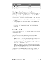
... load using a T-connector or 4-way connector. Choose from a device to be installed - Connect to the backbone at a central point in a bow to stern layout - Wiring | ELITE Ti Installation Manual 29 typically in the backbone to balance the voltage drop of the network. Ú Note: If joining to an existing NMEA 2000 network that is not powered by a 3 amp fuse or...
... load using a T-connector or 4-way connector. Choose from a device to be installed - Connect to the backbone at a central point in a bow to stern layout - Wiring | ELITE Ti Installation Manual 29 typically in the backbone to balance the voltage drop of the network. Ú Note: If joining to an existing NMEA 2000 network that is not powered by a 3 amp fuse or...
Installation Manual EN
Page 30
... individually turned on or off. 2 1 _+ 12 V DC 6 T 3 T 4 54 1 NMEA 2000 device 2 Connector to "Rear connections" on page 13. NMEA 0183 serial port, providing both an input and output for connecting to "NMEA 0183 supported sentences" on page 60. 30 Wiring | ELITE Ti Installation Manual For connection location, refer to unit 3 Drop-cable, should not exceed 6 m (20 ft) 4 Terminators 5 Backbone 6 Power cable...
... individually turned on or off. 2 1 _+ 12 V DC 6 T 3 T 4 54 1 NMEA 2000 device 2 Connector to "Rear connections" on page 13. NMEA 0183 serial port, providing both an input and output for connecting to "NMEA 0183 supported sentences" on page 60. 30 Wiring | ELITE Ti Installation Manual For connection location, refer to unit 3 Drop-cable, should not exceed 6 m (20 ft) 4 Terminators 5 Backbone 6 Power cable...

Installation Manual EN
Page 38
.... Transducer type Transducer type is used for selecting the transducer model connected to the sonar module. Transducer temperature sensors are 38 Software Setup | ELITE Ti Installation Manual Water temperature calibration Temperature calibration is used to adjust the water temperature value from the sonar transducer to match the data from the transducer to the bottom of two impedances - 5k or 10k. A A Keel offset, for example: - 0.3 m (- 1 ft) Before setting...
.... Transducer type Transducer type is used for selecting the transducer model connected to the sonar module. Transducer temperature sensors are 38 Software Setup | ELITE Ti Installation Manual Water temperature calibration Temperature calibration is used to adjust the water temperature value from the sonar transducer to match the data from the transducer to the bottom of two impedances - 5k or 10k. A A Keel offset, for example: - 0.3 m (- 1 ft) Before setting...
Installation Manual EN
Page 39
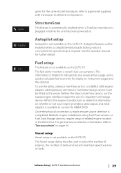
...Setup | ELITE Ti Installation Manual 39 The fuel utility monitors a vessel's fuel consumption. For general source selection information, refer to select the number of engines, the number of a separate Fuel Storage device. given for the same model transducer, refer to paperwork supplied with Navico Fuel Data Storage device must be used to determine impedance. Autopilot setup...sensor, nor the Suzuki engine interface require the use the utility, a Navico Fuel Flow sensor, or a NMEA 2000 engine adaptor cable/gateway with transducer to calculate fuel economy for display on instrument ...
...Setup | ELITE Ti Installation Manual 39 The fuel utility monitors a vessel's fuel consumption. For general source selection information, refer to select the number of engines, the number of a separate Fuel Storage device. given for the same model transducer, refer to paperwork supplied with Navico Fuel Data Storage device must be used to determine impedance. Autopilot setup...sensor, nor the Suzuki engine interface require the use the utility, a Navico Fuel Flow sensor, or a NMEA 2000 engine adaptor cable/gateway with transducer to calculate fuel economy for display on instrument ...
Installation Manual EN
Page 43
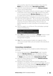
...Setup | ELITE Ti Installation Manual 43 Select the Internal Wireless device on the network are not visible. Select the graphic icon of the unit. Next, select the Mode option and then select Internal Access Point. 2. Next, select the Mode option and then select Internal Access Point. 2. Navigate to the wireless network connection page on screen instructions... device is connected to Access Point mode. the unit should be either the default, or that assigned in range, review the Wireless devices page from the unit's Wireless settings dialog to confirm which wireless device is...
...Setup | ELITE Ti Installation Manual 43 Select the Internal Wireless device on the network are not visible. Select the graphic icon of the unit. Next, select the Mode option and then select Internal Access Point. 2. Next, select the Mode option and then select Internal Access Point. 2. Navigate to the wireless network connection page on screen instructions... device is connected to Access Point mode. the unit should be either the default, or that assigned in range, review the Wireless devices page from the unit's Wireless settings dialog to confirm which wireless device is...
Installation Manual EN
Page 55
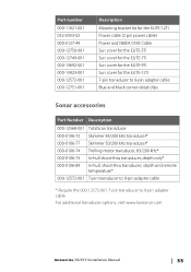
.../200 kHz transducer* 000-0106-74 Trolling motor transducer, 83/200 kHz* 000-0106-73 In-hull shoot-thru transducer, depth only* 000-0106-89 In-hull, shoot-thru transducer, depth and remote temperature* 000-12572-001 7-pin transducer to 9-pin adapter cable * Require the 000-12572-001 7-pin transducer to 9-pin adapter cable For additional transducer options, visit www.lowrance.com Accessories | ELITE Ti Installation Manual 55
.../200 kHz transducer* 000-0106-74 Trolling motor transducer, 83/200 kHz* 000-0106-73 In-hull shoot-thru transducer, depth only* 000-0106-89 In-hull, shoot-thru transducer, depth and remote temperature* 000-12572-001 7-pin transducer to 9-pin adapter cable * Require the 000-12572-001 7-pin transducer to 9-pin adapter cable For additional transducer options, visit www.lowrance.com Accessories | ELITE Ti Installation Manual 55
Operator Manual EN
Page 58
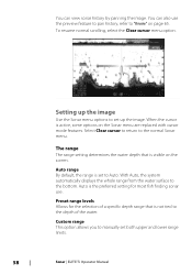
... depth of a specific depth range that is not tied to Auto. When the cursor is set both upper and lower range limits. 58 Sonar | ELITE Ti Operator Manual Preset range levels Allows for most fish finding sonar use the preview feature to pan history, refer to set up the image. The range The range setting determines the water depth that is visible on the screen...
... depth of a specific depth range that is not tied to Auto. When the cursor is set both upper and lower range limits. 58 Sonar | ELITE Ti Operator Manual Preset range levels Allows for most fish finding sonar use the preview feature to pan history, refer to set up the image. The range The range setting determines the water depth that is visible on the screen...
Operator Manual EN
Page 96
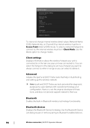
Use the Mode option to Bluetooth enabled devices. 96 Wireless connection | ELITE Ti Operator Manual Navico is connected to or the last one your unit is not the original developer of these tools, and does not provide support related to their use. Use the Bluetooth Device List dialog to pair or remove pairing to ...you can select to delete it as a hotspot you want to always connect to set it . To view and change modes. You can select the hotspot in the dialog to when in fault-finding and setting up the wireless network. Ú Note: Iperf and DHCP Probe are tools ...
Use the Mode option to Bluetooth enabled devices. 96 Wireless connection | ELITE Ti Operator Manual Navico is connected to or the last one your unit is not the original developer of these tools, and does not provide support related to their use. Use the Bluetooth Device List dialog to pair or remove pairing to ...you can select to delete it as a hotspot you want to always connect to set it . To view and change modes. You can select the hotspot in the dialog to when in fault-finding and setting up the wireless network. Ú Note: Iperf and DHCP Probe are tools ...
Declaration of Conformity
Page 1
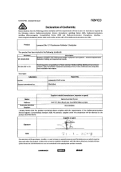
... Act 1992. Product Lowrance Elite-12 Ti Touchscreen Fishfinder / Chartplotter This product has been tested to use which must be identical to maintain compliance with the above . EN 300 328 V1.9.1 Electromagnetic compatibility and Radio spectrum Matters (ERM);...service to the product identified above directives. General requirements Methods of the purchaser, installer, or user is drawn to special measures and limitations to use are contained in the 2,4 GHz ISM band and using wide band modulation techniques. The attention of testing and required test results. LOWRANCE...
... Act 1992. Product Lowrance Elite-12 Ti Touchscreen Fishfinder / Chartplotter This product has been tested to use which must be identical to maintain compliance with the above . EN 300 328 V1.9.1 Electromagnetic compatibility and Radio spectrum Matters (ERM);...service to the product identified above directives. General requirements Methods of the purchaser, installer, or user is drawn to special measures and limitations to use are contained in the 2,4 GHz ISM band and using wide band modulation techniques. The attention of testing and required test results. LOWRANCE...


