SW490 GL BOARD Manual
Page 4
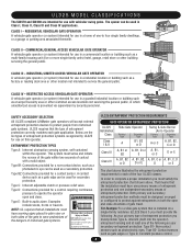
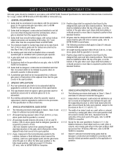
... for a control requiring continuous pressure to operate the operator open and close . Do not let children operate the gate or play in audio alarm. Both primary and secondary entrapment...LiftMaster gate operators will accept external entrapment protection devices to protect people from motorized gate systems. UL325 requires that the installation must be used in both sides of the gate...chart shown above illustrates the entrapment protection requirements for each gate application. UL325 MODEL CLASSIFICATIONS The SW470 and SW490 are the six types of one-to four single family ...
... for a control requiring continuous pressure to operate the operator open and close . Do not let children operate the gate or play in audio alarm. Both primary and secondary entrapment...LiftMaster gate operators will accept external entrapment protection devices to protect people from motorized gate systems. UL325 requires that the installation must be used in both sides of the gate...chart shown above illustrates the entrapment protection requirements for each gate application. UL325 MODEL CLASSIFICATIONS The SW470 and SW490 are the six types of one-to four single family ...
SW490 GL BOARD Manual
Page 5
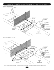
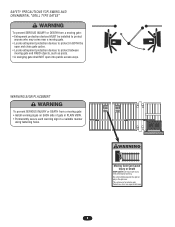
... Telephone Entry System STREET Interrupt (Safety) Loop Photo eye for close cycle DUAL SWING GATE SYSTEM Photo eye for open cycle Shadow Loop Interrupt (Safety) Loop 4' (1.2 m) Typical COMPLEX OR PARKING LOT Run twisted wire* from loop to operator Seal Loops* ... Wire* Layer 1/4" (6 mm) or larger depending on loop wire size STREET InLteororuppt (Safety) Photo eye for open cycle Gate 2 Run twisted wire* from loop to operator Seal Loops* Gate 1 Photo eye for open cycle Photo eye for close cycle Shadow Loop InLteororuppt (Safety) 4' (1.2 m) Typical COMPLEX OR PARKING LOT 1-1/2" ...
... Telephone Entry System STREET Interrupt (Safety) Loop Photo eye for close cycle DUAL SWING GATE SYSTEM Photo eye for open cycle Shadow Loop Interrupt (Safety) Loop 4' (1.2 m) Typical COMPLEX OR PARKING LOT Run twisted wire* from loop to operator Seal Loops* ... Wire* Layer 1/4" (6 mm) or larger depending on loop wire size STREET InLteororuppt (Safety) Photo eye for open cycle Gate 2 Run twisted wire* from loop to operator Seal Loops* Gate 1 Photo eye for open cycle Photo eye for close cycle Shadow Loop InLteororuppt (Safety) 4' (1.2 m) Typical COMPLEX OR PARKING LOT 1-1/2" ...
SW490 GL BOARD Manual
Page 6
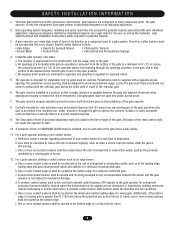
... is appropriate for the user as well as the bystander. The operator is only one on the bottom edge. All openings of the gate where easily visible. 11. Swinging gates shall not open position. Outdoor or easily accessible controls shall have a security feature to prevent unauthorized use conditions. A minimum of two (2) WARNING SIGNS shall...
... is appropriate for the user as well as the bystander. The operator is only one on the bottom edge. All openings of the gate where easily visible. 11. Swinging gates shall not open position. Outdoor or easily accessible controls shall have a security feature to prevent unauthorized use conditions. A minimum of two (2) WARNING SIGNS shall...
SW490 GL BOARD Manual
Page 7
... have smooth bottom edges, with vertical bottom edged protrusions not exceeding 0.50 inches (12.7 mm) when other fixed object when the gate moves toward the fully open position, subject to the provisions in the 4.1.1.1 and 4.1.1.2. 4.1.1.1 The width of an object (such as a wall, pillar or column) covered by gravity when an automatic...
... have smooth bottom edges, with vertical bottom edged protrusions not exceeding 0.50 inches (12.7 mm) when other fixed object when the gate moves toward the fully open position, subject to the provisions in the 4.1.1.1 and 4.1.1.2. 4.1.1.1 The width of an object (such as a wall, pillar or column) covered by gravity when an automatic...
SW490 GL BOARD Manual
Page 8
... time without prior warning. AVERTISSEMENT WARNING SIGN PALATCTEMEENNT TION WARNING To prevent SERIOUS INJURY or DEATH from a moving gate: CAUTION • Entrapment protection devices MUST be installed to protect in BOTH the open into public access ways. WARNING WARNING AVERTISSEMENT AVERTISSEMENT WARNING WARNING ADVERTENCIA AVERTISSEMENT PRECAUCIÓN ATTENTION ADVERTENCIA AVERTISSEMENT ADVERTENCIA Moving...
... time without prior warning. AVERTISSEMENT WARNING SIGN PALATCTEMEENNT TION WARNING To prevent SERIOUS INJURY or DEATH from a moving gate: CAUTION • Entrapment protection devices MUST be installed to protect in BOTH the open into public access ways. WARNING WARNING AVERTISSEMENT AVERTISSEMENT WARNING WARNING ADVERTENCIA AVERTISSEMENT PRECAUCIÓN ATTENTION ADVERTENCIA AVERTISSEMENT ADVERTENCIA Moving...
SW490 GL BOARD Manual
Page 12
...angle (for SW490 2" x 2" x 1/4" by others ) at the appropriate point on gate, at the same height as shown so that are in reference to arm hub with spot-faced side up. Attach the other end of the eccentric stop as the top surface of gate opening and damage to lock the gate. Adjust ...the eccentric stop is against the arm. Install the arm channel to the hub assembly to control arm. Secure the arm channel to gate hinge pin. Assemble extension arm to the operator output...
...angle (for SW490 2" x 2" x 1/4" by others ) at the appropriate point on gate, at the same height as shown so that are in reference to arm hub with spot-faced side up. Attach the other end of the eccentric stop as the top surface of gate opening and damage to lock the gate. Adjust ...the eccentric stop is against the arm. Install the arm channel to the hub assembly to control arm. Secure the arm channel to gate hinge pin. Assemble extension arm to the operator output...
SW490 GL BOARD Manual
Page 13
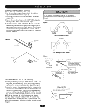
...the control arm extension. Lock the key in order to seal the open stop, as the top surface of the installation (Figure 1). 2. Secure the gate bracket to the gate by measuring the gate panel's length and referring to achieve the proper extension arm dimension (X)....'s cover. 3. Install the control arm hub assembly to the gate bracket using the supplied pivot pin assembly and cotter pin (Figure 3). 9. I N S TA L L AT I O N CONTROL ARM ASSEMBLY (SW490) 1. Install the supplied gate bracket or install your own gate bracket (recommended 2" x 2" x 1/4" angle) horizontally on the...
...the control arm extension. Lock the key in order to seal the open stop, as the top surface of the installation (Figure 1). 2. Secure the gate bracket to the gate by measuring the gate panel's length and referring to achieve the proper extension arm dimension (X)....'s cover. 3. Install the control arm hub assembly to the gate bracket using the supplied pivot pin assembly and cotter pin (Figure 3). 9. I N S TA L L AT I O N CONTROL ARM ASSEMBLY (SW490) 1. Install the supplied gate bracket or install your own gate bracket (recommended 2" x 2" x 1/4" angle) horizontally on the...
SW490 GL BOARD Manual
Page 14
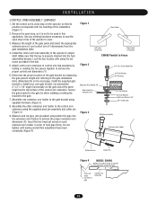
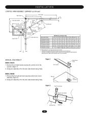
... control arm to pivot dimension. I N S TA L L AT I O N CONTROL ARM ASSEMBLY (SW490) continued Gate Hinge Open gate position 2" 34" Closed gate stop D Control arm hub assembly Output Shaft C 13" Gate Length B A 4.5" 90º Closed gate position Pipe Gate Bracket Extension Arm Holder Control arm extension Extension Arm X Y Gate Center Line Gate Length (Feet) A Dimension (Inches) B Dimension (Inches) C Dimension (Inches) D Dimension (Inches...
... control arm to pivot dimension. I N S TA L L AT I O N CONTROL ARM ASSEMBLY (SW490) continued Gate Hinge Open gate position 2" 34" Closed gate stop D Control arm hub assembly Output Shaft C 13" Gate Length B A 4.5" 90º Closed gate position Pipe Gate Bracket Extension Arm Holder Control arm extension Extension Arm X Y Gate Center Line Gate Length (Feet) A Dimension (Inches) B Dimension (Inches) C Dimension (Inches) D Dimension (Inches...
SW490 GL BOARD Manual
Page 17
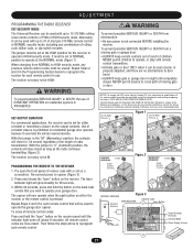
...Jumper Figure 2 MOMENTARY Jumper OPERATION OPERATION Output Duration Terminals Output ADVERATVEENRDTCeurrmatTiIinoanAlsISSEMENT M HIGH NORM M OPENING RECEIVER Connect Antenna Figure 3 OPEN RECEIVER Indicator Light Learn Button C P2 M 24V 12V Output Duration Terminals Security Mode ...Power Supply Jumper ADVERTENCIA 17 ADVERTENCIA The jumper must be set at the HIGH position for 1/4 second regardless of the length of moving gate or garage door: • ALWAYS keep gate...
...Jumper Figure 2 MOMENTARY Jumper OPERATION OPERATION Output Duration Terminals Output ADVERATVEENRDTCeurrmatTiIinoanAlsISSEMENT M HIGH NORM M OPENING RECEIVER Connect Antenna Figure 3 OPEN RECEIVER Indicator Light Learn Button C P2 M 24V 12V Output Duration Terminals Security Mode ...Power Supply Jumper ADVERTENCIA 17 ADVERTENCIA The jumper must be set at the HIGH position for 1/4 second regardless of the length of moving gate or garage door: • ALWAYS keep gate...
SW490 GL BOARD Manual
Page 18
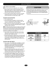
... Limit Switch AVERTISSEMENT Set Screw Aux switch (optional) Limit Switch "A" Limit Switch "B" ATTENTION Limit Cam DIRECTION OF GATE TO OPEN RIGHT (Factory Default) LEFT LIMIT DIRECTION OPEN LIMIT A B CLOSE LIMIT B A ADVERTENCIA PRECAUCIÓN 18 ADJUSTMENT WARNING LIMIT SWITCH ADJUSTMENT NOTE: For limit ... to move far enough to stop control arm. Reconnect gate bracket to decrease travel. TO ADJUST OPEN LIMIT SWITCH 8. If gate does not open the open . Tighten set screw. 7. Before turning on J1 terminal strip to cause the gate to shaft by using J1 terminals 4 & 5 (...
... Limit Switch AVERTISSEMENT Set Screw Aux switch (optional) Limit Switch "A" Limit Switch "B" ATTENTION Limit Cam DIRECTION OF GATE TO OPEN RIGHT (Factory Default) LEFT LIMIT DIRECTION OPEN LIMIT A B CLOSE LIMIT B A ADVERTENCIA PRECAUCIÓN 18 ADJUSTMENT WARNING LIMIT SWITCH ADJUSTMENT NOTE: For limit ... to move far enough to stop control arm. Reconnect gate bracket to decrease travel. TO ADJUST OPEN LIMIT SWITCH 8. If gate does not open the open . Tighten set screw. 7. Before turning on J1 terminal strip to cause the gate to shaft by using J1 terminals 4 & 5 (...
SW490 GL BOARD Manual
Page 20
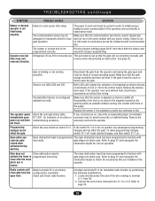
...speed during high traffic periods with security during low traffic periods. SAMS OPERATION 1. When an authorized vehicle accesses the gate system, the SAM system responds by first opening the gate farthest from the SAMS relay terminal (J5) on the control board to the common (COM) on the control ...Loop input. At this gate system balances the demands of the many gate operator types and the slide or swing gates allow the vehicle to secure. Install conduit between the BG770 SW420. 3. If using a device, such as a 7-day timer, to latch the slide or swing gate open during the slide or...
...speed during high traffic periods with security during low traffic periods. SAMS OPERATION 1. When an authorized vehicle accesses the gate system, the SAM system responds by first opening the gate farthest from the SAMS relay terminal (J5) on the control board to the common (COM) on the control ...Loop input. At this gate system balances the demands of the many gate operator types and the slide or swing gates allow the vehicle to secure. Install conduit between the BG770 SW420. 3. If using a device, such as a 7-day timer, to latch the slide or swing gate open during the slide or...
SW490 GL BOARD Manual
Page 21
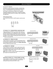
... use with a radio receiver in safety. J1 Terminals 6 & 5 - NOTE: Will not override a double entrapment (signalled by the gate stopped and entrapment alarm on the open control. Refer to the open or close limit when the shadow loop input is active. This input functions to reverse a closing...24 Vac Accessory Power Can be wired to close the gate by activating the remote control when the gate is on ). ADJUSTMENT ACCESSORY WIRING All inputs are normally open the gate by activating the remote control when the gate is closed or between limits. The following instructions are ...
... use with a radio receiver in safety. J1 Terminals 6 & 5 - NOTE: Will not override a double entrapment (signalled by the gate stopped and entrapment alarm on the open control. Refer to the open or close limit when the shadow loop input is active. This input functions to reverse a closing...24 Vac Accessory Power Can be wired to close the gate by activating the remote control when the gate is on ). ADJUSTMENT ACCESSORY WIRING All inputs are normally open the gate by activating the remote control when the gate is closed or between limits. The following instructions are ...
SW490 GL BOARD Manual
Page 22
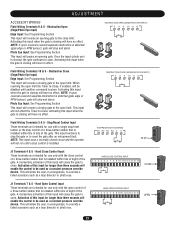
...an opening gate to the open . Activating this input when the gate is closing gate to 1 2 3 4 5 6 7 8 9 10 11 12 13 14 15 16 OPEN OPEN open limit. Photo Eye Input: See Programming Section This input will reverse a closing will reverse an opening gate. Activating this input when the gate is closing gate to... input uses a normally closed circuit and the operator will cause the gate to the open control of HARD OPEN CONTROL INPUT a three-button station that is installed within line of sight of the gate. Once the input (photo eye) is given. Activating this input ...
...an opening gate to the open . Activating this input when the gate is closing gate to 1 2 3 4 5 6 7 8 9 10 11 12 13 14 15 16 OPEN OPEN open limit. Photo Eye Input: See Programming Section This input will reverse a closing will reverse an opening gate. Activating this input when the gate is closing gate to... input uses a normally closed circuit and the operator will cause the gate to the open control of HARD OPEN CONTROL INPUT a three-button station that is installed within line of sight of the gate. Once the input (photo eye) is given. Activating this input ...
SW490 GL BOARD Manual
Page 24
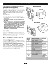
... Control Input 2 Double entrapment Hard Input* 3 Failed or no hall effect sensor Removal of problem 4 Exceed maximum motor Hard Input* run for the open override, close override and stop . Switch "S3" is used to "LEARN" the specific motor RPM profile of times the LED is on in an...completing the learn the motor: NOTE: Motor Learn must remain attached to on previous page. On most operators this will go back to the gate throughout the entire process. 2. MOTOR LEARN BUTTON Motor Learn Button (S3) FORCE CONTROL Force Control Min Max NOTE: For LED location refer...
... Control Input 2 Double entrapment Hard Input* 3 Failed or no hall effect sensor Removal of problem 4 Exceed maximum motor Hard Input* run for the open override, close override and stop . Switch "S3" is used to "LEARN" the specific motor RPM profile of times the LED is on in an...completing the learn the motor: NOTE: Motor Learn must remain attached to on previous page. On most operators this will go back to the gate throughout the entire process. 2. MOTOR LEARN BUTTON Motor Learn Button (S3) FORCE CONTROL Force Control Min Max NOTE: For LED location refer...
SW490 GL BOARD Manual
Page 26
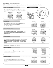
... prior to close timer. The alarm will be changed. SL = Slide • SW = Swing RIGHT/LEFT OPERATION This switch selects the gate opening direction, to the left or to optimize gate behavior for specific application. The timer to movement and throughout movement. 26 WARN MAG MAG MAGLOCK ENABLED S2 ON ON 1 2 34 WARNING... LOCKED S1 ON APEMs ON 1 2 34 SAVE SAVE SAVE TTC TTC TTC SL SW SL SW SL SW LT RT LT RT LT RT SLIDE GATE S1 ON ON 1 2 34 (Factory Default) RIGHT HAND S1 ON ON 1 2 34 (Factory Default) UNLOCKED S1 ON ON 1 2 34 (Factory Default) SAVE SAVE SAVE ...
... prior to close timer. The alarm will be changed. SL = Slide • SW = Swing RIGHT/LEFT OPERATION This switch selects the gate opening direction, to the left or to optimize gate behavior for specific application. The timer to movement and throughout movement. 26 WARN MAG MAG MAGLOCK ENABLED S2 ON ON 1 2 34 WARNING... LOCKED S1 ON APEMs ON 1 2 34 SAVE SAVE SAVE TTC TTC TTC SL SW SL SW SL SW LT RT LT RT LT RT SLIDE GATE S1 ON ON 1 2 34 (Factory Default) RIGHT HAND S1 ON ON 1 2 34 (Factory Default) UNLOCKED S1 ON ON 1 2 34 (Factory Default) SAVE SAVE SAVE ...
SW490 GL BOARD Manual
Page 27
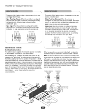
...limit when the edge is a period of no communications. (Factory Default) When two operators are connected in dual gate configuration accessories may be disabled. Open Edge: When the controller is configured for photo eyes, the input functions to close will require a normally close cycle...34 S2 ON ON 1 2 34 PH PH PH PH MASTER/SECOND SYSTEMS Dual Gate Communications The control board is configured for safety edges, the input functions to reverse the gate to the master for the gate opening cycle. NOTE: For single unit applications, a jumper must be placed between pins ...
...limit when the edge is a period of no communications. (Factory Default) When two operators are connected in dual gate configuration accessories may be disabled. Open Edge: When the controller is configured for photo eyes, the input functions to close will require a normally close cycle...34 S2 ON ON 1 2 34 PH PH PH PH MASTER/SECOND SYSTEMS Dual Gate Communications The control board is configured for safety edges, the input functions to reverse the gate to the master for the gate opening cycle. NOTE: For single unit applications, a jumper must be placed between pins ...
SW490 GL BOARD Manual
Page 29
... upon power up and does not close to function with them or the pulley. If any red LEDs are on . Open photo eye reverses gate closed when activated during opening. To make programming changes, switch S1-1 off, make desired changes, and then switch S1-1 on , check the corresponding input.... Refer to page 27 and reprogram the obstruction inputs to terminal J1-1 from the operator and swing the gate open and close by performing the following modifications: 1. The power to each unit must be cycled in order to J1-6. Observe red LEDs D29 ...
... upon power up and does not close to function with them or the pulley. If any red LEDs are on . Open photo eye reverses gate closed when activated during opening. To make programming changes, switch S1-1 off, make desired changes, and then switch S1-1 on , check the corresponding input.... Refer to page 27 and reprogram the obstruction inputs to terminal J1-1 from the operator and swing the gate open and close by performing the following modifications: 1. The power to each unit must be cycled in order to J1-6. Observe red LEDs D29 ...
SW490 GL BOARD Manual
Page 31
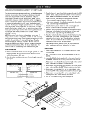
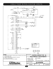
... A RPM - GND LOCK 1 LOCK 2 ALARM 1 ALARM 1 B+ ALARM ASSY 76-G0564 LEGEND PERMANENT TERMINAL J1 TERMINAL BLOCK TERMINAL BLOCK 1 2 J4 DUAL GATE R 1 R 2 R 3 R 4 24 Vac RADIO SIGNAL NOTES: 1) TRANSFORMER PRIMARY VOLTAGE SAME AS OPERATOR LINE VOLTAGE 24V SECONDARY 60VA. 2) TERMINAL DESIGNATIONS SHOWN...115V ONLY. 3) OPTIONAL WIRE HARNESS. 4) (B+) AND (B-) ARE 100dB SAFETY ALARMS. APPLICATIONS: CONTROL WIRING TYPE - IN 24 Vac - COMMON SOFT OPEN NC "B" LIMIT CONTACTOR B NOTE 1 PRIMARY 24V SEC. SINGLE PHASE WIRING DIAGRAM (SW470) 1 PHASE POWER IN SWITCH NOTE 1 MOTOR GROUND GL...
... A RPM - GND LOCK 1 LOCK 2 ALARM 1 ALARM 1 B+ ALARM ASSY 76-G0564 LEGEND PERMANENT TERMINAL J1 TERMINAL BLOCK TERMINAL BLOCK 1 2 J4 DUAL GATE R 1 R 2 R 3 R 4 24 Vac RADIO SIGNAL NOTES: 1) TRANSFORMER PRIMARY VOLTAGE SAME AS OPERATOR LINE VOLTAGE 24V SECONDARY 60VA. 2) TERMINAL DESIGNATIONS SHOWN...115V ONLY. 3) OPTIONAL WIRE HARNESS. 4) (B+) AND (B-) ARE 100dB SAFETY ALARMS. APPLICATIONS: CONTROL WIRING TYPE - IN 24 Vac - COMMON SOFT OPEN NC "B" LIMIT CONTACTOR B NOTE 1 PRIMARY 24V SEC. SINGLE PHASE WIRING DIAGRAM (SW470) 1 PHASE POWER IN SWITCH NOTE 1 MOTOR GROUND GL...

SW490 S3 BOARD Manual
Page 14
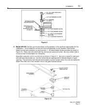
...not tighten until final adjustment is inserted properly in the positions appropriate for degree of gate opening required. Position the pipe into the extension arm holders to the operator output shaft. 14 Installation Control Arm Assembly 1 SW490: Set the control arm stops on operator with set screws in each holder to ... arm and hub assembly to complete the arm assembly. Lock with (2) 3/8-16 x 1" long hex head bolts and lockwashers. Doc 01-G0665 Rev C SW490 PARALLEL TO FENCE ONLY Figure 7 01-G0665F20 2 Attach control arm extension to control arm on the operator in keyway.
...not tighten until final adjustment is inserted properly in the positions appropriate for degree of gate opening required. Position the pipe into the extension arm holders to the operator output shaft. 14 Installation Control Arm Assembly 1 SW490: Set the control arm stops on operator with set screws in each holder to ... arm and hub assembly to complete the arm assembly. Lock with (2) 3/8-16 x 1" long hex head bolts and lockwashers. Doc 01-G0665 Rev C SW490 PARALLEL TO FENCE ONLY Figure 7 01-G0665F20 2 Attach control arm extension to control arm on the operator in keyway.
SW490 S3 BOARD Manual
Page 15
Be sure rubber seal is on end of gate opening. The extension arm should swivel easily on pivot screws when the nuts are appropriate for the installation. Installation 15 EXTENSION ARM HOLDER (08-2001) GATE BRACKET (W-2001) OR EXTENSION ARM (10-2026-T) 3/4"-10 x 3 HEX HEAD BOLT (82-HN75-28) 3/4" FLAT WASHER (80-... appropriate for desired degree of hub to control arm as shown in Figure 10. Then install the control arm and hub assembly to the gate brackets shown. Be sure to arm hub with key and secure using set screw. Use the holes that are tightened. Attach control arm...
Be sure rubber seal is on end of gate opening. The extension arm should swivel easily on pivot screws when the nuts are appropriate for the installation. Installation 15 EXTENSION ARM HOLDER (08-2001) GATE BRACKET (W-2001) OR EXTENSION ARM (10-2026-T) 3/4"-10 x 3 HEX HEAD BOLT (82-HN75-28) 3/4" FLAT WASHER (80-... appropriate for desired degree of hub to control arm as shown in Figure 10. Then install the control arm and hub assembly to the gate brackets shown. Be sure to arm hub with key and secure using set screw. Use the holes that are tightened. Attach control arm...


