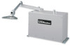
SW490 GL BOARD Manual
Page 2
... Arm and Gate Bracket Installation (SW470 12 Control Arm Assembly (SW490 13-14 Manual Disconnect 14 WIRING AVERTISSEMENT Power Wiring Installation 15 On/Off Switch Power Wiring 16 Stop/Reset Button Control Wiring 16 ADJAUSTTMTEENTNTION Programming the Radio Receiver 17 Limit Switch Adjustment 18 RPM Sensor (Hall Effect) Adjustment 19 SAMS (Sequenced Access Management System 20 Accessory Wiring 21-22 Control Board Illustration 23 Controller Programming and Features 24-25 Program Settings 26-27 TROUBLESHOOTING 28-29 MAINTENANCE Operator Maintenance 30 Single Phase Wiring Diagram...
... Arm and Gate Bracket Installation (SW470 12 Control Arm Assembly (SW490 13-14 Manual Disconnect 14 WIRING AVERTISSEMENT Power Wiring Installation 15 On/Off Switch Power Wiring 16 Stop/Reset Button Control Wiring 16 ADJAUSTTMTEENTNTION Programming the Radio Receiver 17 Limit Switch Adjustment 18 RPM Sensor (Hall Effect) Adjustment 19 SAMS (Sequenced Access Management System 20 Accessory Wiring 21-22 Control Board Illustration 23 Controller Programming and Features 24-25 Program Settings 26-27 TROUBLESHOOTING 28-29 MAINTENANCE Operator Maintenance 30 Single Phase Wiring Diagram...
SW490 GL BOARD Manual
Page 5
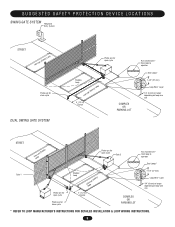
... DEVICE LOCATIONS SWING GATE SYSTEM Telephone Entry System STREET Interrupt (Safety) Loop Photo eye for close cycle DUAL SWING GATE SYSTEM Photo eye for open cycle Shadow Loop Interrupt (Safety) Loop 4' (1.2 m) Typical COMPLEX OR PARKING LOT Run twisted wire* from loop to operator Seal Loops* 1-1/2" (37 mm) Loop Wire* Layer 1/4" (6 mm) or larger depending on loop wire size STREET InLteororuppt (Safety) Photo eye for open cycle Gate 2 Run twisted wire* from loop to operator Seal Loops* Gate 1 Photo eye for open cycle Photo eye for close cycle Shadow Loop InLteororuppt (Safety...
... DEVICE LOCATIONS SWING GATE SYSTEM Telephone Entry System STREET Interrupt (Safety) Loop Photo eye for close cycle DUAL SWING GATE SYSTEM Photo eye for open cycle Shadow Loop Interrupt (Safety) Loop 4' (1.2 m) Typical COMPLEX OR PARKING LOT Run twisted wire* from loop to operator Seal Loops* 1-1/2" (37 mm) Loop Wire* Layer 1/4" (6 mm) or larger depending on loop wire size STREET InLteororuppt (Safety) Photo eye for open cycle Gate 2 Run twisted wire* from loop to operator Seal Loops* Gate 1 Photo eye for open cycle Photo eye for close cycle Shadow Loop InLteororuppt (Safety...
SW490 GL BOARD Manual
Page 6
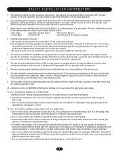
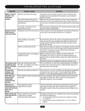
... its wiring arranged so the communication between the gate and adjacent structures when opening shall be located on the bottom edge. SAFETY INSTALLATION INFORMATION 1. Locate the gate such that transmits radio frequency (RF) signals to potential hazards. 3. One or more contact sensors shall be installed, one that persons will not come in its arc of travel of travel , one component. A gate operator can create risks for user...
... its wiring arranged so the communication between the gate and adjacent structures when opening shall be located on the bottom edge. SAFETY INSTALLATION INFORMATION 1. Locate the gate such that transmits radio frequency (RF) signals to potential hazards. 3. One or more contact sensors shall be installed, one that persons will not come in its arc of travel of travel , one component. A gate operator can create risks for user...
SW490 GL BOARD Manual
Page 13
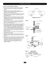
... pivot pin assembly and cotter pin (Figure 3). 9. Remove the open stop's hole in the hub. 5. Assemble one extension arm holder to the control arm extension using the set screws in each extension arm holder in this application. Install the control arm hub assembly to achieve the proper extension arm dimension (X). Set the control arm's close stop , as the top surface of the control arm extension. Determine the proper location of the installation (Figure 1). 2. Attach control arm extension to control arm hub assembly by either welding or bolting the bracket to...
... pivot pin assembly and cotter pin (Figure 3). 9. Remove the open stop's hole in the hub. 5. Assemble one extension arm holder to the control arm extension using the set screws in each extension arm holder in this application. Install the control arm hub assembly to achieve the proper extension arm dimension (X). Set the control arm's close stop , as the top surface of the control arm extension. Determine the proper location of the installation (Figure 1). 2. Attach control arm extension to control arm hub assembly by either welding or bolting the bracket to...
SW490 GL BOARD Manual
Page 17
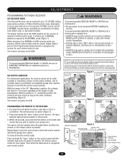
... undesired operation. When changing from a moving gate or door. SET OUTPUT DURATION For commercial applications, the receiver can be set at NORMAL position to operate at the NORMAL mode (Figure 1). THERE ARE NO OTHER USER SERVICEABLE PARTS. With the jumper in NORMAL security mode, including any combination of rolling code, billion code, or dip switch remotes. Press and release the "learn indicator light will glow steadily for 30 seconds. 3. To erase all remote control codes...
... undesired operation. When changing from a moving gate or door. SET OUTPUT DURATION For commercial applications, the receiver can be set at NORMAL position to operate at the NORMAL mode (Figure 1). THERE ARE NO OTHER USER SERVICEABLE PARTS. With the jumper in NORMAL security mode, including any combination of rolling code, billion code, or dip switch remotes. Press and release the "learn indicator light will glow steadily for 30 seconds. 3. To erase all remote control codes...
SW490 GL BOARD Manual
Page 18
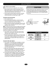
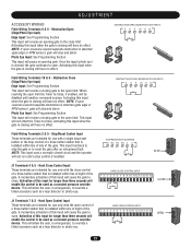
.... Rotate cam in close . Drive Shaft Limit Switch AVERTISSEMENT Set Screw Aux switch (optional) Limit Switch "A" Limit Switch "B" ATTENTION Limit Cam DIRECTION OF GATE TO OPEN RIGHT (Factory Default) LEFT LIMIT DIRECTION OPEN LIMIT A B CLOSE LIMIT B A ADVERTENCIA PRECAUCIÓN 18 Turn on electrical power. 4. Push manual release pin(s) up through the control arm, slide clevis pin in correct direction. 6. CAUTION When following limit switch adjustment procedure, the motor belt will turn freely. Press CLOSE button (if installed) or connect terminals 4 & 5 on J1...
.... Rotate cam in close . Drive Shaft Limit Switch AVERTISSEMENT Set Screw Aux switch (optional) Limit Switch "A" Limit Switch "B" ATTENTION Limit Cam DIRECTION OF GATE TO OPEN RIGHT (Factory Default) LEFT LIMIT DIRECTION OPEN LIMIT A B CLOSE LIMIT B A ADVERTENCIA PRECAUCIÓN 18 Turn on electrical power. 4. Push manual release pin(s) up through the control arm, slide clevis pin in correct direction. 6. CAUTION When following limit switch adjustment procedure, the motor belt will turn freely. Press CLOSE button (if installed) or connect terminals 4 & 5 on J1...
SW490 GL BOARD Manual
Page 20
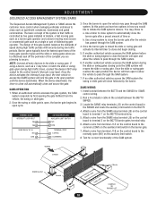
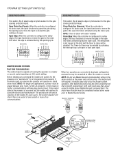
... BG770 BARRIER GATE AUXILIARY LIMIT SWITCH N/0 COM TERMINAL STRIP 1 (OPEN) 3 (COMMON) 3. Use a timer to close system to automatically close the barrier gate after the vehicle has passed through the SAM system. Locate the SAMS relay terminals (J5) on the BG770 terminal strip. 5. TRAFFIC SAMS Conduit STREET Hold Open Loop Master Second Shadow Loop Safety Loop COMPLEX OR PARKING LOT 20 If using a device, such as a 7-day timer, to access the...
... BG770 BARRIER GATE AUXILIARY LIMIT SWITCH N/0 COM TERMINAL STRIP 1 (OPEN) 3 (COMMON) 3. Use a timer to close system to automatically close the barrier gate after the vehicle has passed through the SAM system. Locate the SAMS relay terminals (J5) on the BG770 terminal strip. 5. TRAFFIC SAMS Conduit STREET Hold Open Loop Master Second Shadow Loop Safety Loop COMPLEX OR PARKING LOT 20 If using a device, such as a 7-day timer, to access the...
SW490 GL BOARD Manual
Page 21
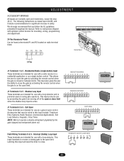
... use as a single button control. NOTE: Will not override a double entrapment (signalled by activating the remote control when the gate is closed or between limits. Latching this input include: Telephone Entry Systems, Radio Receiver (Commercial Applications), Exit Loop Detector, Keypads, 7-Day Timer. The following instructions are intended for significant increase in a residential application or as a general open or close limit when the shadow loop input is active. This allows the user to close the gate...
... use as a single button control. NOTE: Will not override a double entrapment (signalled by activating the remote control when the gate is closed or between limits. Latching this input include: Telephone Entry Systems, Radio Receiver (Commercial Applications), Exit Loop Detector, Keypads, 7-Day Timer. The following instructions are intended for significant increase in a residential application or as a general open or close limit when the shadow loop input is active. This allows the user to close the gate...
SW490 GL BOARD Manual
Page 22
... a loop detector or photo eye. 22 Hard Close Control Input These terminals are intended for use only with a single stop/reset button or the stop and alarm. Photo Eye Input: See Programming Section This input will be disabled until a stop and alarm. A momentary activation of the gate. NOTE: If upon reversal a second separate obstruction is detected (gate edge or RPM sensor), gate will allow the user, in emergencies, to the open control of HARD OPEN CONTROL INPUT a three-button...
... a loop detector or photo eye. 22 Hard Close Control Input These terminals are intended for use only with a single stop/reset button or the stop and alarm. Photo Eye Input: See Programming Section This input will be disabled until a stop and alarm. A momentary activation of the gate. NOTE: If upon reversal a second separate obstruction is detected (gate edge or RPM sensor), gate will allow the user, in emergencies, to the open control of HARD OPEN CONTROL INPUT a three-button...
SW490 GL BOARD Manual
Page 24
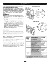
... mode. 1. ADJUSTMENT CONTROL BOARD PROGRAMMING AND FEATURES MOTOR LEARN FUNCTION (FORCE PROFILE) This function is replaced, the controller will need to be programmed to "LEARN" the specific motor RPM profile of your operator. If either the hard open and close limits. FORCE CONTROL Set the force control pot such that the jumper is in learn or some other error occurs, the LED will run mode On No Flash Motor not learned Completion of between the different diagnostic codes. LED Code Flashed OFF Diagnostic Meaning Normal operation Cleared By N/A 1 Single...
... mode. 1. ADJUSTMENT CONTROL BOARD PROGRAMMING AND FEATURES MOTOR LEARN FUNCTION (FORCE PROFILE) This function is replaced, the controller will need to be programmed to "LEARN" the specific motor RPM profile of your operator. If either the hard open and close limits. FORCE CONTROL Set the force control pot such that the jumper is in learn or some other error occurs, the LED will run mode On No Flash Motor not learned Completion of between the different diagnostic codes. LED Code Flashed OFF Diagnostic Meaning Normal operation Cleared By N/A 1 Single...
SW490 GL BOARD Manual
Page 27
... to reverse the gate to the open limit when activated during travel . In this mode no further communications will reset if enabled. The Second unit will be enabled by activating the interrupt loop, soft open or hard open . After Master/Second wiring has been completed and the S4 switch programmed, both units must have their power cycled to query the second unit during the close cycle. Open Photo Eye (Pause): When the controller...
... to reverse the gate to the open limit when activated during travel . In this mode no further communications will reset if enabled. The Second unit will be enabled by activating the interrupt loop, soft open or hard open . After Master/Second wiring has been completed and the S4 switch programmed, both units must have their power cycled to query the second unit during the close cycle. Open Photo Eye (Pause): When the controller...
SW490 GL BOARD Manual
Page 29
... any subsequent programming changes will Radio terminals R1-4 are on the control board. Review program settings pages 26-27 and check both the master and second for dual gate operation. This pot must be wired incorrectly or malfunctioning. Make sure that the gate will result in stand-alone mode. Open obstruction input is adjusted correctly but then stops and reverses direction. close after setup. The Hall Effect Sensor is not programmed correctly...
... any subsequent programming changes will Radio terminals R1-4 are on the control board. Review program settings pages 26-27 and check both the master and second for dual gate operation. This pot must be wired incorrectly or malfunctioning. Make sure that the gate will result in stand-alone mode. Open obstruction input is adjusted correctly but then stops and reverses direction. close after setup. The Hall Effect Sensor is not programmed correctly...
SW490 GL BOARD Manual
Page 35
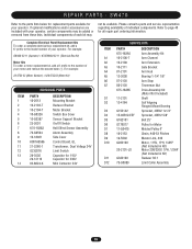
... DESCRIPTION Arm Assembly Kit Arm Channel Arm Extension Gate Bracket Arm Hub Bearing 1-1/4" 1/8" Arm Stop Tinnerman Nut Drive Assembly Kit (Motor Not Included) Shaft Self Aligning Flanged Mount Bearing Sprocket, 40B42 1x1/4" Sprocket, 40B12 5/8" Belt 25" Pulley for all repair part ordering information. Individual components of your operator. SW470 Refer to the model number of each kit may be available. Refer to the number of individual components. For example: SW420-33-11 (Operator) = K73SW420-33-11 (Electrical Box Kit) Motor Kits To order a motor replacement kit, add...
... DESCRIPTION Arm Assembly Kit Arm Channel Arm Extension Gate Bracket Arm Hub Bearing 1-1/4" 1/8" Arm Stop Tinnerman Nut Drive Assembly Kit (Motor Not Included) Shaft Self Aligning Flanged Mount Bearing Sprocket, 40B42 1x1/4" Sprocket, 40B12 5/8" Belt 25" Pulley for all repair part ordering information. Individual components of your operator. SW470 Refer to the model number of each kit may be available. Refer to the number of individual components. For example: SW420-33-11 (Operator) = K73SW420-33-11 (Electrical Box Kit) Motor Kits To order a motor replacement kit, add...
SW490 GL BOARD Manual
Page 40
... send this product. HOW TO ORDER REPAIR PARTS OUR LARGE SERVICE ORGANIZATION SPANS AMERICA FOR INSTALLATION AND SERVICE INFORMATION, CALL OUR TOLL FREE NUMBER 1-800-528-2806 www.liftmaster.com WHEN ORDERING REPAIR PARTS PLEASE SUPPLY THE FOLLOWING INFORMATION: PART NUMBER DESCRIPTION MODEL NUMBER ADDRESS ORDER TO: THE CHAMBERLAIN GROUP, INC. All Rights Reserved WARRANTY POLICY AND SERVICE LIFTMASTER® TWO YEAR LIMITED WARRANTY The Chamberlain Group, Inc. If, during the...
... send this product. HOW TO ORDER REPAIR PARTS OUR LARGE SERVICE ORGANIZATION SPANS AMERICA FOR INSTALLATION AND SERVICE INFORMATION, CALL OUR TOLL FREE NUMBER 1-800-528-2806 www.liftmaster.com WHEN ORDERING REPAIR PARTS PLEASE SUPPLY THE FOLLOWING INFORMATION: PART NUMBER DESCRIPTION MODEL NUMBER ADDRESS ORDER TO: THE CHAMBERLAIN GROUP, INC. All Rights Reserved WARRANTY POLICY AND SERVICE LIFTMASTER® TWO YEAR LIMITED WARRANTY The Chamberlain Group, Inc. If, during the...
SW490 S3 BOARD Manual
Page 7
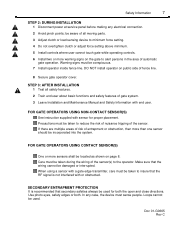
... or adjust force setting above minimum. 5 Install controls where user cannot touch gate while operating controls. 6 Install two or more than one sensor should be conspicuous. 7 Install operator inside fence line. be used for proper placement. Loops cannot be aware of all safety features. 2 Train end user about basic functions and safety features of fence line. 8 Secure gate operator cover. Safety Information 7 STEP 2: DURING INSTALLATION 1 Disconnect power at service panel before making any case, the device must be located...
... or adjust force setting above minimum. 5 Install controls where user cannot touch gate while operating controls. 6 Install two or more than one sensor should be conspicuous. 7 Install operator inside fence line. be used for proper placement. Loops cannot be aware of all safety features. 2 Train end user about basic functions and safety features of fence line. 8 Secure gate operator cover. Safety Information 7 STEP 2: DURING INSTALLATION 1 Disconnect power at service panel before making any case, the device must be located...

SW490 S3 BOARD Manual
Page 9
... the National Electrical Code and allows for wiring specifications. Supply voltage must be level. ! this application. ! H. I. Do not run control wires in the same conduit with power wires. VOLT 24 CONTROL WIRING MAX. DISTANCE 1000 WIRE GUAGE 18 Table 4: Control Wiring Chart NOTE: Calculated using NEC guidelines. Master/Slave units must be reviewed for suitability of the operator's rating under load conditions. If wiring has already been installed, check to...
... the National Electrical Code and allows for wiring specifications. Supply voltage must be level. ! this application. ! H. I. Do not run control wires in the same conduit with power wires. VOLT 24 CONTROL WIRING MAX. DISTANCE 1000 WIRE GUAGE 18 Table 4: Control Wiring Chart NOTE: Calculated using NEC guidelines. Master/Slave units must be reviewed for suitability of the operator's rating under load conditions. If wiring has already been installed, check to...

SW490 S3 BOARD Manual
Page 19
... using master/slave, only set time per the chart on a limit Blinking 1 flash per second = Normal operation (gate travel or mid-stop) Blinking 2 flashes per second = Entrapment level 1 (operator reverse to ON. POLE #4 - SINGLE/CLOSE BUTTON ON = Close button only OFF = Open/Close Button POLE #2 - OFF = Warning device disabled. 0 1-0 66 5 F1 2 Figure 17 Timer to close is on page 20. SINGLE UNIT ON = Master or single Unit OFF = Slave unit RED LED INFORMATION Continuous ON = Unit is locked out at the factory, to activate the timer to close program...
... using master/slave, only set time per the chart on a limit Blinking 1 flash per second = Normal operation (gate travel or mid-stop) Blinking 2 flashes per second = Entrapment level 1 (operator reverse to ON. POLE #4 - SINGLE/CLOSE BUTTON ON = Close button only OFF = Open/Close Button POLE #2 - OFF = Warning device disabled. 0 1-0 66 5 F1 2 Figure 17 Timer to close is on page 20. SINGLE UNIT ON = Master or single Unit OFF = Slave unit RED LED INFORMATION Continuous ON = Unit is locked out at the factory, to activate the timer to close program...
SW490 S3 BOARD Manual
Page 21
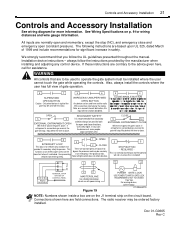
... 12 MASTER/SLAVE Use shielded twisted pair. This functions as an wireless open ) the gate if active. Note left/right switch does not effect direction. 3 5 STOP BUTTON - Loops cannot be ordered factory installed. Figure 19 13 14 POWER GATE LOCK USE POWER TO MATCH GATE LOCK REQUIREMENTS, NOT TO EXCEED 115V 10A. Controls and Accessory Installation 21 Controls and Accessory Installation See wiring diagram for wiring distances and wire gauge information. Installation device instructions - CLOSE 5 10 EXTERNAL ENTRAPMENT CLOSE Will reverse (open...
... 12 MASTER/SLAVE Use shielded twisted pair. This functions as an wireless open ) the gate if active. Note left/right switch does not effect direction. 3 5 STOP BUTTON - Loops cannot be ordered factory installed. Figure 19 13 14 POWER GATE LOCK USE POWER TO MATCH GATE LOCK REQUIREMENTS, NOT TO EXCEED 115V 10A. Controls and Accessory Installation 21 Controls and Accessory Installation See wiring diagram for wiring distances and wire gauge information. Installation device instructions - CLOSE 5 10 EXTERNAL ENTRAPMENT CLOSE Will reverse (open...
SW490 S3 BOARD Manual
Page 24
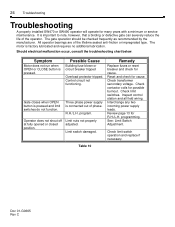
... at fully opened or closed position. Check limit switches. Inspect control station and all field wiring. See: Limit Switch Adjustment. The motor is pressed and limit switches do not function. Gate closes when OPEN button is factory lubricated and requires no additional lubrication. Check limit switch operation and replace if necessary. program. Limit switch damaged. Review page 13 for possible burnout. 24 Troubleshooting Troubleshooting A properly installed SW470 or SW490 operator will operate for many years with a minimum or service maintenance. R.H./L.H. Three phase...
... at fully opened or closed position. Check limit switches. Inspect control station and all field wiring. See: Limit Switch Adjustment. The motor is pressed and limit switches do not function. Gate closes when OPEN button is factory lubricated and requires no additional lubrication. Check limit switch operation and replace if necessary. program. Limit switch damaged. Review page 13 for possible burnout. 24 Troubleshooting Troubleshooting A properly installed SW470 or SW490 operator will operate for many years with a minimum or service maintenance. R.H./L.H. Three phase...

SW490 S3 BOARD Manual
Page 31
... of LiftMaster. FOR TECHNICAL SUPPORT TO ORDER REPAIR PARTS Call our toll free numbers: Call our toll free numbers: (800) 323-2276 (800) 998-9197 (800) 528-2806 (800) 998-9197 Installation and service information is protected by copyright and contain information proprietary to LiftMaster and such information may not be distributed without the prior written consent of LiftMaster. The software and firmware included in the LiftMaster product...
... of LiftMaster. FOR TECHNICAL SUPPORT TO ORDER REPAIR PARTS Call our toll free numbers: Call our toll free numbers: (800) 323-2276 (800) 998-9197 (800) 528-2806 (800) 998-9197 Installation and service information is protected by copyright and contain information proprietary to LiftMaster and such information may not be distributed without the prior written consent of LiftMaster. The software and firmware included in the LiftMaster product...


