
Owners Manual
Page 1
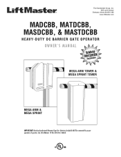
Use (2) LiftMaster 12 Vdc 7AH (Part # MBAT). The Chamberlain Group, Inc. 845 Larch Avenue Elmhurst, Illinois 60126-1196 www.liftmaster.com MADCBB, MATDCBB, MASDCBB, & MASTDCBB HEAVY-DUTY DC BARRIER GATE OPERATOR OWNER'S MANUAL RREINCACELDUIIVDOEEDR MEGA ARM TOWER & MEGA SPRINT TOWER MEGA ARM & MEGA SPRINT IMPORTANT: Read and understand Warranty Page first. Batteries (included) MUST be connected for proper operation of operator.
Use (2) LiftMaster 12 Vdc 7AH (Part # MBAT). The Chamberlain Group, Inc. 845 Larch Avenue Elmhurst, Illinois 60126-1196 www.liftmaster.com MADCBB, MATDCBB, MASDCBB, & MASTDCBB HEAVY-DUTY DC BARRIER GATE OPERATOR OWNER'S MANUAL RREINCACELDUIIVDOEEDR MEGA ARM TOWER & MEGA SPRINT TOWER MEGA ARM & MEGA SPRINT IMPORTANT: Read and understand Warranty Page first. Batteries (included) MUST be connected for proper operation of operator.
Owners Manual
Page 2
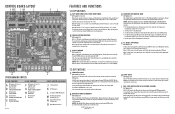
... 19 20 21 21 21 21 22 22 22 22 22 23 24 SAFETY » SAFETY SYMBOL AND SIGNAL WORD REVIEW When you see this manual and follow all safety instructions. • DO NOT attempt repair or service of California to cause cancer or birth defects or other reproductive harm. Read...
... 19 20 21 21 21 21 22 22 22 22 22 23 24 SAFETY » SAFETY SYMBOL AND SIGNAL WORD REVIEW When you see this manual and follow all safety instructions. • DO NOT attempt repair or service of California to cause cancer or birth defects or other reproductive harm. Read...
Owners Manual
Page 4
... not obstructed or impeded by a moving . The Stop and/or Reset (if provided separately) must be supplied with each type of a gate system. Reference owner's manual regarding placement of non-contact sensor for entrapment protection functions shall be located in its function as the one on the bottom edge. c. A wireless contact...
... not obstructed or impeded by a moving . The Stop and/or Reset (if provided separately) must be supplied with each type of a gate system. Reference owner's manual regarding placement of non-contact sensor for entrapment protection functions shall be located in its function as the one on the bottom edge. c. A wireless contact...
Owners Manual
Page 9
... make gate reverse and go back to avoid chafing. When released gate will close gate after input is on the control board C18 U18 C15 F MANUAL 1 2 3 4 5 6 7 8 9 1Ø 11 12 OPEN Q2 J5 S3 T2 T4 T6 T8 T1 T3 T5 T7 CLOSE OPEN 1 OPEN 2 OPEN 3 R21 AUX 4 SAFETY 5 CLOSE 6 BACK 7 SHADOW...
... make gate reverse and go back to avoid chafing. When released gate will close gate after input is on the control board C18 U18 C15 F MANUAL 1 2 3 4 5 6 7 8 9 1Ø 11 12 OPEN Q2 J5 S3 T2 T4 T6 T8 T1 T3 T5 T7 CLOSE OPEN 1 OPEN 2 OPEN 3 R21 AUX 4 SAFETY 5 CLOSE 6 BACK 7 SHADOW...
Owners Manual
Page 12
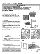
... receiver case with up to 31 of any type remote in sight until the indicator light turns off (about 6 seconds). JJ55 FIGURE 1 C18 U18 C15 1 MANUAL 1 2 3 4 5 6 7 8 9 1Ø 11 12 UX LIMITS M/S J3 R14 Q2 OPEN J5 23 D1 456 R1Ø R9 R8 R7 R6 R5 R4 R3 D9 R2 C18... U18 C15 DJ121Ø 1 AUX LIMITS M/S J3 R14 S3 MANUAL R18 Q2 OPEN 1 2 3 4 5 6 7 8 9 1Ø 11 12 J5 T2 T1 T4 T3 T6 T5 T8 T7 78 D8 D1Ø S2S1 1 2345678 S2 1 2345678 R1 1 2R12...
... receiver case with up to 31 of any type remote in sight until the indicator light turns off (about 6 seconds). JJ55 FIGURE 1 C18 U18 C15 1 MANUAL 1 2 3 4 5 6 7 8 9 1Ø 11 12 UX LIMITS M/S J3 R14 Q2 OPEN J5 23 D1 456 R1Ø R9 R8 R7 R6 R5 R4 R3 D9 R2 C18... U18 C15 DJ121Ø 1 AUX LIMITS M/S J3 R14 S3 MANUAL R18 Q2 OPEN 1 2 3 4 5 6 7 8 9 1Ø 11 12 J5 T2 T1 T4 T3 T6 T5 T8 T7 78 D8 D1Ø S2S1 1 2345678 S2 1 2345678 R1 1 2R12...
Owners Manual
Page 13
... sure the Fast Run Timer settings DO NOT overrun the slow down time. D HANDING THE BARRIER ARM DIP Switch S1-7 The J4 Motor Wiring is manually forced UP (OPEN), the barrier arm will automatically CLOSE. D12 D14 F3 R13 U19 J4 BAT- BAT+ 24VAC XFMR MOTOR Blue Orange 3. Connect power to...
... sure the Fast Run Timer settings DO NOT overrun the slow down time. D HANDING THE BARRIER ARM DIP Switch S1-7 The J4 Motor Wiring is manually forced UP (OPEN), the barrier arm will automatically CLOSE. D12 D14 F3 R13 U19 J4 BAT- BAT+ 24VAC XFMR MOTOR Blue Orange 3. Connect power to...
Owners Manual
Page 15
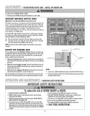
...adjustments (IF ARM DOES NOT REVERSE, DO NOT CONTINUE TO FORCE). 1 Place an obstruction in the HORIZONTAL POSITION. Read the owner's manual. Have a qualified service person make repairs to ensure proper operation. After adjusting the force or the limit of limit sensor Control Board Screws...to gate hardware. 3. Keep the remote control away from the gate. Test the gate operator monthly. ALL maintenance MUST be done by a LiftMaster professional. 10. INSTANT REVERSE DEVICE (IRD) Adjustments to travel between each sensor. • If the arm is TOO sensitive. WARNING After ...
...adjustments (IF ARM DOES NOT REVERSE, DO NOT CONTINUE TO FORCE). 1 Place an obstruction in the HORIZONTAL POSITION. Read the owner's manual. Have a qualified service person make repairs to ensure proper operation. After adjusting the force or the limit of limit sensor Control Board Screws...to gate hardware. 3. Keep the remote control away from the gate. Test the gate operator monthly. ALL maintenance MUST be done by a LiftMaster professional. 10. INSTANT REVERSE DEVICE (IRD) Adjustments to travel between each sensor. • If the arm is TOO sensitive. WARNING After ...
Owners Manual
Page 16
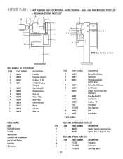
... (Operator) Gate Arm Bracket Barrier Arm BATTERY BATTERY DISPOSAL Replaced batteries must be treated as required Bearings and Shafts Check for manually initiating the battery test. Replace in the field. See the Battery Test Description section for wear and lubricate ● Battery ...Maintenance Replace batteries. ◆ Repeat ALL procedures. BATTERY HANDLING / STORAGE Refer to put gate into collar. 7. LiftMaster does not recommend storage of in accordance with hammer and punch (Solid sharp blows are available for battery replacement. Replacement must be ...
... (Operator) Gate Arm Bracket Barrier Arm BATTERY BATTERY DISPOSAL Replaced batteries must be treated as required Bearings and Shafts Check for manually initiating the battery test. Replace in the field. See the Battery Test Description section for wear and lubricate ● Battery ...Maintenance Replace batteries. ◆ Repeat ALL procedures. BATTERY HANDLING / STORAGE Refer to put gate into collar. 7. LiftMaster does not recommend storage of in accordance with hammer and punch (Solid sharp blows are available for battery replacement. Replacement must be ...
Owners Manual
Page 20
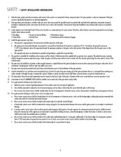
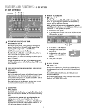
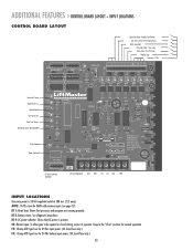
... Sense (IRD and MRT) Relay Indicator Relay (Optional) 1 1 J2 AUX LIMITS M/S J3 R14 D8 D1Ø R18 S1 S2 1 2345678 1 2345678 R1 R12 R17 R16 MANUAL Q2 OPEN 1 2 3 4 5 6 7 8 9 1Ø 11 12 J5 S3 T2 T4 T6 T8 T1 T3 T5 T7 OPEN 1 OPEN 2 OPEN 3 AUX 4 SAFETY 5CLOSE 6 BACK 7SHADOW 8 ... F4: 15 amp ATO type fuse for normal operation. NOTE: J5 #8 is 24 Vdc regulated rated at 500 ma. [1/2 amp]. See diagnostic procedures. S3: Manual open. To allow gate to be opened or closed during service of operator. Reader, Push Button Aux Open / Reset (Pulse Open/Close) Safety Loop Input...
... Sense (IRD and MRT) Relay Indicator Relay (Optional) 1 1 J2 AUX LIMITS M/S J3 R14 D8 D1Ø R18 S1 S2 1 2345678 1 2345678 R1 R12 R17 R16 MANUAL Q2 OPEN 1 2 3 4 5 6 7 8 9 1Ø 11 12 J5 S3 T2 T4 T6 T8 T1 T3 T5 T7 OPEN 1 OPEN 2 OPEN 3 AUX 4 SAFETY 5CLOSE 6 BACK 7SHADOW 8 ... F4: 15 amp ATO type fuse for normal operation. NOTE: J5 #8 is 24 Vdc regulated rated at 500 ma. [1/2 amp]. See diagnostic procedures. S3: Manual open. To allow gate to be opened or closed during service of operator. Reader, Push Button Aux Open / Reset (Pulse Open/Close) Safety Loop Input...
Owners Manual
Page 22
... Arm Bracket 11 MA011 Magnet 12 MA012 Cam Arm 13 MA013 Shear Pin PARTS SHIPPED ITEM MEGA ARM Operator Controller Operator Cover Installation and Service Manual Arm Bolts with Washers Nylon Nuts 7AH Batteries ITEM PART NUMBER 14 MA014 15 MA015 16 MA016 17 MA017 19 MA019 * MA020 * MA021 * MA022 * MA023...
... Arm Bracket 11 MA011 Magnet 12 MA012 Cam Arm 13 MA013 Shear Pin PARTS SHIPPED ITEM MEGA ARM Operator Controller Operator Cover Installation and Service Manual Arm Bolts with Washers Nylon Nuts 7AH Batteries ITEM PART NUMBER 14 MA014 15 MA015 16 MA016 17 MA017 19 MA019 * MA020 * MA021 * MA022 * MA023...
Quick Start Guide
Page 1
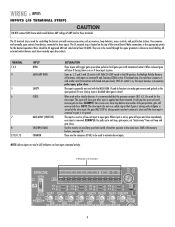
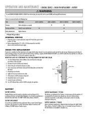
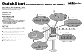
...ACC+ ACC- D The J4 Motor Wiring is determined by changing various DIP switches, and wiring auxiliary devices to the installation manual for complete information regarding installation and programming. Refer to the control board on AC Power Failure). INTRODUCTION The operator functions can be...to open and close the barrier arm from the control board. A DIP Switches ON ON S1 S2 1 2345678 1 2345678 OFF OFF B Manual Switch MANUAL OPEN S3 CLOSE J5 C J5 Terminal Strip (Wiring Inputs) 123456789 J5 F Limit Cam Position CAM POSITION E K1 Relay (optional) and Terminal...
...ACC+ ACC- D The J4 Motor Wiring is determined by changing various DIP switches, and wiring auxiliary devices to the installation manual for complete information regarding installation and programming. Refer to the control board on AC Power Failure). INTRODUCTION The operator functions can be...to open and close the barrier arm from the control board. A DIP Switches ON ON S1 S2 1 2345678 1 2345678 OFF OFF B Manual Switch MANUAL OPEN S3 CLOSE J5 C J5 Terminal Strip (Wiring Inputs) 123456789 J5 F Limit Cam Position CAM POSITION E K1 Relay (optional) and Terminal...
Quick Start Guide
Page 2
.... Turning multiple switches ON will remain OPEN before CLOSING. Any of the closing barrier arm. I DIP Switch S2-8 FAIL SAFE O INPUT/OUTPUT LOCATIONS J S3 Manual Switch K J5 Wiring Inputs L J5 Common (COM) Wiring Inputs M K1 Relay (optional) and Terminal Strip (J1) N Accessory Output Power (300 mA) ... radio wire from right-hand to S1-4 DIP switches. CONTROL BOARD LAYOUT A BCDE F GH I J K L 1 1 J2 AUX LIMITS M/S D8 S1 12 R1 R12 J3 R14 R16 MANUAL 1 2 3 4 5 6 7 8 9 1Ø 11 12 OPEN Q2 J5 S3 T2 T1 OPEN 1 OPEN 2 CLOSE R21 T4 T3 OPEN 3 AUX 4 T6 T8 T5 T7 SAFETY 5...
.... Turning multiple switches ON will remain OPEN before CLOSING. Any of the closing barrier arm. I DIP Switch S2-8 FAIL SAFE O INPUT/OUTPUT LOCATIONS J S3 Manual Switch K J5 Wiring Inputs L J5 Common (COM) Wiring Inputs M K1 Relay (optional) and Terminal Strip (J1) N Accessory Output Power (300 mA) ... radio wire from right-hand to S1-4 DIP switches. CONTROL BOARD LAYOUT A BCDE F GH I J K L 1 1 J2 AUX LIMITS M/S D8 S1 12 R1 R12 J3 R14 R16 MANUAL 1 2 3 4 5 6 7 8 9 1Ø 11 12 OPEN Q2 J5 S3 T2 T1 OPEN 1 OPEN 2 CLOSE R21 T4 T3 OPEN 3 AUX 4 T6 T8 T5 T7 SAFETY 5...


