
MA/MAT Product Data Sheet
Page 1
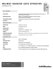
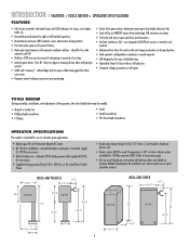
... of a power loss REMOTE CONTROL ACCESS Security+ 2.0® 3-channel receiver will handle up to 90 remote controls (unlimited remotes with yellow padding COVER MA - MA/MAT BARRIER GATE OPERATOR SECTION 32 31 00 KEY FEATURES BATTERY BACKUP Up to 900 cycles seamless operation between barrier gate and all DC control and sensing devices in the event of AC power or battery depletion LIMIT SETTING Magnetic SPECIFICATIONS OPERATOR SPEED Opening time: 2.5 seconds POWER 120V/230VAC single phase ACCESSORY POWER 24VDC, 500mA OPERATOR WEIGHT...
... of a power loss REMOTE CONTROL ACCESS Security+ 2.0® 3-channel receiver will handle up to 90 remote controls (unlimited remotes with yellow padding COVER MA - MA/MAT BARRIER GATE OPERATOR SECTION 32 31 00 KEY FEATURES BATTERY BACKUP Up to 900 cycles seamless operation between barrier gate and all DC control and sensing devices in the event of AC power or battery depletion LIMIT SETTING Magnetic SPECIFICATIONS OPERATOR SPEED Opening time: 2.5 seconds POWER 120V/230VAC single phase ACCESSORY POWER 24VDC, 500mA OPERATOR WEIGHT...
Owners Manual
Page 2
... Operator Specifications INSTALLATION Install the Concrete Pad and Conduit Attach the Operator to the Concrete Pad Install the Barrier Arm WIRING Power Wiring Input Commands Connections Accessory and Relay Connections Battery Installation Primary/Second Wiring INSTALL THE RECEIVER FEATURES AND FUNCTIONS S1 DIP Switches S2 DIP Switches ADJUSTMENTS Instant Reverse Device (IRD) Adjust the Barrier Arm 2-4 2 3 4 5 5 5 5 6-7 6 7 7 8-11 8 9 10 10 11 12 13-14 13 14 OPERATION AND MAINTENANCE Important Safety Instructions General Service Shear Pin Replacement Battery ADDITIONAL FEATURES Suggested Loop...
... Operator Specifications INSTALLATION Install the Concrete Pad and Conduit Attach the Operator to the Concrete Pad Install the Barrier Arm WIRING Power Wiring Input Commands Connections Accessory and Relay Connections Battery Installation Primary/Second Wiring INSTALL THE RECEIVER FEATURES AND FUNCTIONS S1 DIP Switches S2 DIP Switches ADJUSTMENTS Instant Reverse Device (IRD) Adjust the Barrier Arm 2-4 2 3 4 5 5 5 5 6-7 6 7 7 8-11 8 9 10 10 11 12 13-14 13 14 OPERATION AND MAINTENANCE Important Safety Instructions General Service Shear Pin Replacement Battery ADDITIONAL FEATURES Suggested Loop...
Owners Manual
Page 3
... provide Type A inherent (built into the operator) entrapment sensing and at any time without prior warning. Contact sensors such as a multi-family housing unit (five or more single family units) hotel, garage, retail store or other building servicing the general public. Constant pressure control. 3 COMMERCIAL/GENERAL ACCESS VEHICULAR GATE OPERATOR II A vehicular gate operator (or system) intended for use in audio alarm. ENTRAPMENT PROTECTION TYPES Type...
... provide Type A inherent (built into the operator) entrapment sensing and at any time without prior warning. Contact sensors such as a multi-family housing unit (five or more single family units) hotel, garage, retail store or other building servicing the general public. Constant pressure control. 3 COMMERCIAL/GENERAL ACCESS VEHICULAR GATE OPERATOR II A vehicular gate operator (or system) intended for use in audio alarm. ENTRAPMENT PROTECTION TYPES Type...
Owners Manual
Page 4
... of application. Outdoor or easily accessible controls shall have a security feature to start. 10. Reference owner's manual regarding placement of a vehicular vertical lift gate. A wireless contact sensor such as the bystander. One or more contact sensors shall be located where the transmission of entrapment. The gate operator is intended for installation only on the bottom edge. Specific safety features include: • Gate Edges • Screen Mesh •...
... of application. Outdoor or easily accessible controls shall have a security feature to start. 10. Reference owner's manual regarding placement of a vehicular vertical lift gate. A wireless contact sensor such as the bystander. One or more contact sensors shall be located where the transmission of entrapment. The gate operator is intended for installation only on the bottom edge. Specific safety features include: • Gate Edges • Screen Mesh •...
Owners Manual
Page 5
... tail-gating is sensed at close travel if tail-gating is sensed. • SAMS with eight inputs and LED indicators for loops, card reader, radio, etc. • Reversible arm direction for accessories • Capable of the operator, the tools listed below . uses magnetic (Hall Effect) sensors to fail - INTRODUCTION » FEATURES + TOOLS NEEDED + OPERATOR SPECIFICATIONS FEATURES • Full service controller with "memory" - Molded Polyethylene UV stabilized cover never...
... tail-gating is sensed at close travel if tail-gating is sensed. • SAMS with eight inputs and LED indicators for loops, card reader, radio, etc. • Reversible arm direction for accessories • Capable of the operator, the tools listed below . uses magnetic (Hall Effect) sensors to fail - INTRODUCTION » FEATURES + TOOLS NEEDED + OPERATOR SPECIFICATIONS FEATURES • Full service controller with "memory" - Molded Polyethylene UV stabilized cover never...
Owners Manual
Page 6
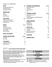
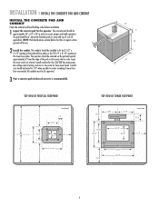
... of curb (if applicable). The operator should be UL approved. 3 Pour a concrete pad (reinforced concrete is recommended). 24" 6" 18" 24" TOP VIEW OF PEDESTAL FOOTPRINT (concrete pad) 8" 2" 12" 5-1/2" 8" 5-1/2" 6" 3-1/2" 12" 9" 8" TOP VIEW OF TOWER FOOTPRINT 5-1/4" 7-1/8" (gate arm bracket) 7-1/8" (concrete pad) 3-1/2" 9-7/8" 13-1/2" 10-1/4" 8-1/4" 6" 5-1/4" (door) 12-1/4" 14-1/4" 6 Install conduits for the 120/230 Vac main power, low voltage control wiring, and one or two extra...
... of curb (if applicable). The operator should be UL approved. 3 Pour a concrete pad (reinforced concrete is recommended). 24" 6" 18" 24" TOP VIEW OF PEDESTAL FOOTPRINT (concrete pad) 8" 2" 12" 5-1/2" 8" 5-1/2" 6" 3-1/2" 12" 9" 8" TOP VIEW OF TOWER FOOTPRINT 5-1/4" 7-1/8" (gate arm bracket) 7-1/8" (concrete pad) 3-1/2" 9-7/8" 13-1/2" 10-1/4" 8-1/4" 6" 5-1/4" (door) 12-1/4" 14-1/4" 6 Install conduits for the 120/230 Vac main power, low voltage control wiring, and one or two extra...
Owners Manual
Page 8
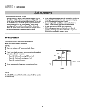
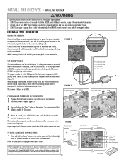
... and secured, at that you install an optional reversing edge BEFORE proceeding with local electrical codes. Connect AC power to the operator: • Connect the black wire to the incoming 120 Vac hot lead. • Connect the white wire to the incoming neutral lead. • Connect the green wire to the ground. 3 Do not connect any wiring or attempt to service. • Disconnect power at the fuse box BEFORE proceeding. Operator MUST...
... and secured, at that you install an optional reversing edge BEFORE proceeding with local electrical codes. Connect AC power to the operator: • Connect the black wire to the incoming 120 Vac hot lead. • Connect the white wire to the incoming neutral lead. • Connect the green wire to the ground. 3 Do not connect any wiring or attempt to service. • Disconnect power at the fuse box BEFORE proceeding. Operator MUST...
Owners Manual
Page 9
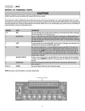
... exit loop and gate closes. EXAMPLE: Car crosses over close gate after input is re-opened. NOTE: The close input. SAMS with timed anti-pass back). NOTE: Above inputs are the commons (0 Vdc) to be routed through the upper grommet in the same lane. Wires should be used as receivers, loop detectors, access controls, and push button stations. Input is disabled when gate is generally not used with the MEGA ARM. WIRING...
... exit loop and gate closes. EXAMPLE: Car crosses over close gate after input is re-opened. NOTE: The close input. SAMS with timed anti-pass back). NOTE: Above inputs are the commons (0 Vdc) to be routed through the upper grommet in the same lane. Wires should be used as receivers, loop detectors, access controls, and push button stations. Input is disabled when gate is generally not used with the MEGA ARM. WIRING...
Owners Manual
Page 10
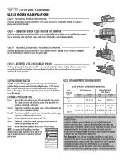
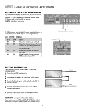
... 12 BATTERY INSTALLATION CONNECTING THE BATTERY LEADS - Replace batteries in place. Failure to install batteries correctly will cause damage and will not be covered by the close loop ANTI TAIL-GATE ALARM. EXAMPLE: Vehicle detector, radio receiver. K1 D11 U19 Aux Relay J1 C NC NO DC 1 PWR D12 R13 J4 D14 BAT- 1 F3 MOV ACC+ ACC- BAT- Relay will fire when arm is pushed up off of limit switch (use with slip...
... 12 BATTERY INSTALLATION CONNECTING THE BATTERY LEADS - Replace batteries in place. Failure to install batteries correctly will cause damage and will not be covered by the close loop ANTI TAIL-GATE ALARM. EXAMPLE: Vehicle detector, radio receiver. K1 D11 U19 Aux Relay J1 C NC NO DC 1 PWR D12 R13 J4 D14 BAT- 1 F3 MOV ACC+ ACC- BAT- Relay will fire when arm is pushed up off of limit switch (use with slip...
Owners Manual
Page 12
... to opener (Figure 3). 2 Press and release the "learn " button on either the receiver or the remote control is factory set at HIGH. TO ERASE ALL REMOTE CONTROL CODES 1 Press and hold the button on the receiver terminal strip are for each remote control that will now operate when the push button on the receiver panel until completely closed. Follow the steps above to 15 rolling code remotes or passwords in use. THERE ARE NO OTHER USER SERVICEABLE PARTS.
... to opener (Figure 3). 2 Press and release the "learn " button on either the receiver or the remote control is factory set at HIGH. TO ERASE ALL REMOTE CONTROL CODES 1 Press and hold the button on the receiver terminal strip are for each remote control that will now operate when the push button on the receiver panel until completely closed. Follow the steps above to 15 rolling code remotes or passwords in use. THERE ARE NO OTHER USER SERVICEABLE PARTS.
Owners Manual
Page 13
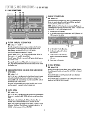
... arm and just behind the limit sensor. 6. B SINGLE BUTTON FUNCTION (INCLUDING PULSE RADIO RECEIVER OPEN/CLOSE) DIP Switch S1-5 With S1-5 DIP switch in the CLOSED position. The Handing of the S1-1 to S1-4 DIP switches. MO MOTOR 1 ACC+ ACC- Set DIP switch S1-7 to the operator. 2. Turn the Limit Cam so the Limit Cam is wired into the K1 Relay and terminal strip (J1). When S1-8 DIP switch is reached. If the Close Loop...
... arm and just behind the limit sensor. 6. B SINGLE BUTTON FUNCTION (INCLUDING PULSE RADIO RECEIVER OPEN/CLOSE) DIP Switch S1-5 With S1-5 DIP switch in the CLOSED position. The Handing of the S1-1 to S1-4 DIP switches. MO MOTOR 1 ACC+ ACC- Set DIP switch S1-7 to the operator. 2. Turn the Limit Cam so the Limit Cam is wired into the K1 Relay and terminal strip (J1). When S1-8 DIP switch is reached. If the Close Loop...
Owners Manual
Page 15
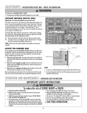
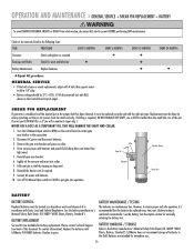
... SAFETY INSTRUCTIONS WARNING To reduce the risk of SERIOUS INJURY or DEATH: • Disconnect power BEFORE performing ANY adjustments near drive shaft. NEVER let children operate or play with a rigid object or stop , time out (using the time delay set at S-2 switches 1-5) and then close limit. • If the arm is closing too far: Loosen the control board screws and slide the Location of INJURY or DEATH. 7. Read the owner's manual. Test the gate operator...
... SAFETY INSTRUCTIONS WARNING To reduce the risk of SERIOUS INJURY or DEATH: • Disconnect power BEFORE performing ANY adjustments near drive shaft. NEVER let children operate or play with a rigid object or stop , time out (using the time delay set at S-2 switches 1-5) and then close limit. • If the arm is closing too far: Loosen the control board screws and slide the Location of INJURY or DEATH. 7. Read the owner's manual. Test the gate operator...
Owners Manual
Page 16
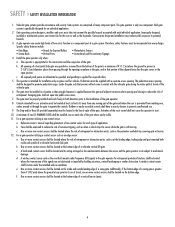
... support motor to ensure proper and safe operation, it must be treated as required Bearings and Shafts Check for immediate use a drill bit smaller than light ones). 5. Lightly oil the new pin and insert into operation. Connect AC power and batteries. 10. Collar Shear Pin (Operator) Gate Arm Bracket Barrier Arm BATTERY BATTERY DISPOSAL Replaced batteries must be done by tapping on the Control Board Layout page). Replace in collar. 4. See the Battery Test Description section for contact information). LiftMaster...
... support motor to ensure proper and safe operation, it must be treated as required Bearings and Shafts Check for immediate use a drill bit smaller than light ones). 5. Lightly oil the new pin and insert into operation. Connect AC power and batteries. 10. Collar Shear Pin (Operator) Gate Arm Bracket Barrier Arm BATTERY BATTERY DISPOSAL Replaced batteries must be done by tapping on the Control Board Layout page). Replace in collar. 4. See the Battery Test Description section for contact information). LiftMaster...
Owners Manual
Page 18
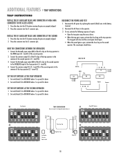
... 12345678 TRAP CONFIGURATION Must use trap kit. See Mega Arm Options Parts List Close Loop Trap Close Loop Trap Close Loop Close Loop Card Reader Tele-entry Radio Control Mega Arm Trap Mega Arm SS11 Mega ARM Operator ON ON ON ON ON ON ON ON OFF 12345678 SS22 ON ON ON ON ON ON ON OFF OFF 12345678 18 term#12). RECONNECT THE POWER AND TEST 1. Set switch bank S1 to the...
... 12345678 TRAP CONFIGURATION Must use trap kit. See Mega Arm Options Parts List Close Loop Trap Close Loop Trap Close Loop Close Loop Card Reader Tele-entry Radio Control Mega Arm Trap Mega Arm SS11 Mega ARM Operator ON ON ON ON ON ON ON ON OFF 12345678 SS22 ON ON ON ON ON ON ON OFF OFF 12345678 18 term#12). RECONNECT THE POWER AND TEST 1. Set switch bank S1 to the...
Owners Manual
Page 19
... to work with the other operator's safety loops, safety edges and reverse sensors WILL NOT cause the arm to their open limit switch. As long as cause the arm to the other operators common and open or teeth locked down until the arm closes completely). • In this will keep the K1 relay latched down until the arm reaches the down ) the other operator is 4 wires between the MEGA ARM barrier gate and...
... to work with the other operator's safety loops, safety edges and reverse sensors WILL NOT cause the arm to their open limit switch. As long as cause the arm to the other operators common and open or teeth locked down until the arm closes completely). • In this will keep the K1 relay latched down until the arm reaches the down ) the other operator is 4 wires between the MEGA ARM barrier gate and...
Owners Manual
Page 21
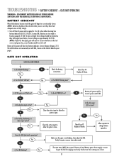
... in a real power loss, even if mode switch 8 on ? The max timer (MRT) has expired. Inspect the belt for 5 to charge before operation. TROUBLESHOOTING » BATTERY CHECKOUT + GATE NOT OPERATING WARNING - Yes Is the "BAT LO" LED on the Control Board Layout page). No No Yes Is the AC PWR LED on now? Does the IRD light while operating? Verify the gate reverses when obstructed. If LED 12 comes...
... in a real power loss, even if mode switch 8 on ? The max timer (MRT) has expired. Inspect the belt for 5 to charge before operation. TROUBLESHOOTING » BATTERY CHECKOUT + GATE NOT OPERATING WARNING - Yes Is the "BAT LO" LED on the Control Board Layout page). No No Yes Is the AC PWR LED on now? Does the IRD light while operating? Verify the gate reverses when obstructed. If LED 12 comes...
Owners Manual
Page 22
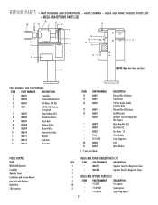
... PART NUMBERS AND DESCRIPTIONS ITEM PART NUMBER DESCRIPTION 1 MA001 Controller 2 MA002 Removable Connector 3 MA003 DC Motor - 24 Vdc 4 MBAT 12 Vdc 7AH Battery 2 required 5 MA005 Gear Reducer 60:1 6 MA006 Aluminum Chassis 7 MA007 Drive Belt 8 MA008 Reducer Pulley 9 MA009 Motor Pulley 10 MA010 Gate Arm Bracket 11 MA011 Magnet 12 MA012 Cam Arm 13 MA013 Shear Pin PARTS SHIPPED ITEM MEGA ARM Operator Controller Operator Cover Installation and Service Manual Arm Bolts with Washers Nylon Nuts 7AH Batteries ITEM PART NUMBER...
... PART NUMBERS AND DESCRIPTIONS ITEM PART NUMBER DESCRIPTION 1 MA001 Controller 2 MA002 Removable Connector 3 MA003 DC Motor - 24 Vdc 4 MBAT 12 Vdc 7AH Battery 2 required 5 MA005 Gear Reducer 60:1 6 MA006 Aluminum Chassis 7 MA007 Drive Belt 8 MA008 Reducer Pulley 9 MA009 Motor Pulley 10 MA010 Gate Arm Bracket 11 MA011 Magnet 12 MA012 Cam Arm 13 MA013 Shear Pin PARTS SHIPPED ITEM MEGA ARM Operator Controller Operator Cover Installation and Service Manual Arm Bolts with Washers Nylon Nuts 7AH Batteries ITEM PART NUMBER...
Owners Manual
Page 24
... battery installation, operation without notice. 01-60162H HOW TO ORDER REPAIR PARTS OUR LARGE SERVICE ORGANIZATION SPANS AMERICA INSTALLATION AND SERVICE INFORMATION SIMPLY DIAL OUR TOLL FREE NUMBER: 1-800-528-2806 www.liftmaster.com WHEN ORDERING REPAIR PARTS, ALWAYS GIVE THE FOLLOWING INFORMATION: • PART NUMBER • PART NAME • MODEL NUMBER ADDRESS ORDERS TO: THE CHAMBERLAIN GROUP, INC. be repaired or replaced free of God (lightning, floods, insect damage, etc.), power surges, units subjected to LiftMaster...
... battery installation, operation without notice. 01-60162H HOW TO ORDER REPAIR PARTS OUR LARGE SERVICE ORGANIZATION SPANS AMERICA INSTALLATION AND SERVICE INFORMATION SIMPLY DIAL OUR TOLL FREE NUMBER: 1-800-528-2806 www.liftmaster.com WHEN ORDERING REPAIR PARTS, ALWAYS GIVE THE FOLLOWING INFORMATION: • PART NUMBER • PART NAME • MODEL NUMBER ADDRESS ORDERS TO: THE CHAMBERLAIN GROUP, INC. be repaired or replaced free of God (lightning, floods, insect damage, etc.), power surges, units subjected to LiftMaster...
Quick Start Guide
Page 1
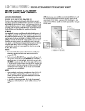
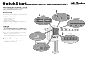
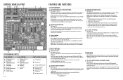
... is wired to the control board on AC Power Failure). DEFAULT SETTINGS ARE AS FOLLOWS: • Timer-to-Close is activated and set to four seconds. • Radio receiver is used for normal operation. The DIP switch settings can be customized by changing various DIP switches, and wiring auxiliary devices to open and close the barrier arm from the control board. NOTE: The S3 DIP switch should be set to -Close, Single Button Function, and Fail Safe (Auto Open on...
... is wired to the control board on AC Power Failure). DEFAULT SETTINGS ARE AS FOLLOWS: • Timer-to-Close is activated and set to four seconds. • Radio receiver is used for normal operation. The DIP switch settings can be customized by changing various DIP switches, and wiring auxiliary devices to open and close the barrier arm from the control board. NOTE: The S3 DIP switch should be set to -Close, Single Button Function, and Fail Safe (Auto Open on...
Quick Start Guide
Page 2
... arm is set to the left -hand operation reverse the motor wires on J4-7 (blue wire) and J4-8 (orange wire) (see backside of control board) until the pre-authorized number of the terminals 9-12 on reverse side). Any of vehicles pass over the Close Loop. ©2010 The Chamberlain Group, Inc. Turn the Limit Cam position 90 degrees to 2-3/8 seconds by DIP switch S1-7. The maximum hold OPEN time is controlled...
... arm is set to the left -hand operation reverse the motor wires on J4-7 (blue wire) and J4-8 (orange wire) (see backside of control board) until the pre-authorized number of the terminals 9-12 on reverse side). Any of vehicles pass over the Close Loop. ©2010 The Chamberlain Group, Inc. Turn the Limit Cam position 90 degrees to 2-3/8 seconds by DIP switch S1-7. The maximum hold OPEN time is controlled...


