

LA400 Manual
Page 2
... Control Box (XLM) WIRING Connect the Gate Operator (Gate 1) to the Control Box Set the Bipart Delay (Model LA400-S Only) Connect the Gate Operator (Gate 2) to the Control Box (Model LA400-S Only) Junction Box (Model LA400-S Only) Connect Transformer to Control Board Earth Ground Rod Installation (Optional) Connect Batteries 1-6 1 2 3 4 5-6 ...-21 22-28 22 23 24 25-26 27 28 28 ADJUSTMENT Set DIP Switch Limits Force Adjustment Timer-to-Close PROGRAMMING Remote Controls Keyless Entry Erase All Codes Test ADDITIONAL FEATURES DIP Switch Settings Control Inputs Loop Inputs Photo/Edge Inputs (P6-7-8 ...
... Control Box (XLM) WIRING Connect the Gate Operator (Gate 1) to the Control Box Set the Bipart Delay (Model LA400-S Only) Connect the Gate Operator (Gate 2) to the Control Box (Model LA400-S Only) Junction Box (Model LA400-S Only) Connect Transformer to Control Board Earth Ground Rod Installation (Optional) Connect Batteries 1-6 1 2 3 4 5-6 ...-21 22-28 22 23 24 25-26 27 28 28 ADJUSTMENT Set DIP Switch Limits Force Adjustment Timer-to-Close PROGRAMMING Remote Controls Keyless Entry Erase All Codes Test ADDITIONAL FEATURES DIP Switch Settings Control Inputs Loop Inputs Photo/Edge Inputs (P6-7-8 ...
LA400 Manual
Page 35
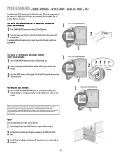
... (NOT PROVIDED) 1 Press LEARN XMITTER button and release (LED will light up ). PROGRAMMING » REMOTE CONTROLS + KEYLESS ENTRY + ERASE ALL CODES + TEST A combined total of 50 remote controls and keyless entry PIN can be programmed to Accessories. LEARN R1 XMITTER 2 To program additional remote controls, repeat steps until the learn indicator light goes out (approximately 6 seconds...
... (NOT PROVIDED) 1 Press LEARN XMITTER button and release (LED will light up ). PROGRAMMING » REMOTE CONTROLS + KEYLESS ENTRY + ERASE ALL CODES + TEST A combined total of 50 remote controls and keyless entry PIN can be programmed to Accessories. LEARN R1 XMITTER 2 To program additional remote controls, repeat steps until the learn indicator light goes out (approximately 6 seconds...
LA400 Manual
Page 40
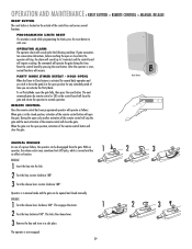
... the reset button to normal operation. After the operator is in a safe place. RESET RESET Reset Button REMOTE CONTROL Once the remote control has been programmed operator will sound under the following condition: If gate encounters two consecutive obstructions, before reaching the open the ... 1 Turn the release lever clockwise 180°. This engages the motor. 1 2 Turn the key clockwise 180°. PARTY MODE (TIMER DEFEAT - PROGRAMMING LIMITS RESET If a mistake is now engaged. 39 2 3 2 3 OPERATOR ALARM The operator alarm will operate as follows: When gate is reset...
... the reset button to normal operation. After the operator is in a safe place. RESET RESET Reset Button REMOTE CONTROL Once the remote control has been programmed operator will sound under the following condition: If gate encounters two consecutive obstructions, before reaching the open the ... 1 Turn the release lever clockwise 180°. This engages the motor. 1 2 Turn the key clockwise 180°. PARTY MODE (TIMER DEFEAT - PROGRAMMING LIMITS RESET If a mistake is now engaged. 39 2 3 2 3 OPERATOR ALARM The operator alarm will operate as follows: When gate is reset...

LA400 Manual
Page 42
Jog Learn Limit Single Button Force Bipart Delay Timer-to-Close Receiver Program Remote Gate 1 - P1 D6 O1 2 3 4 5 N TROUBLESHOOTING » BASIC CONTROL BOARD LAYOUT BASIC CONTROL BOARD LAYOUT 20 19 17 26 1 14 13 18 12 11* 10 21 ...
Jog Learn Limit Single Button Force Bipart Delay Timer-to-Close Receiver Program Remote Gate 1 - P1 D6 O1 2 3 4 5 N TROUBLESHOOTING » BASIC CONTROL BOARD LAYOUT BASIC CONTROL BOARD LAYOUT 20 19 17 26 1 14 13 18 12 11* 10 21 ...

LA400 Manual
Page 44
...Arm installation. 1) Obstructed Arm (bottoms out). 2) Bad RPM Sensor. 3) Too much mA pulled off board. Replace control board. See Programming Remote instructions. Check STOP connections. Move accessories to -Close not turned on. 2) Gate has opened on . 3) Loose/disconnected wires. 4) ... obstruction on next page to board. 2) Bad control board. 1) Low/disconnected battery. 2) Remote not programmed. 3) STOP connection loose/disconnected. 4) Constant Open Command (Check LED's). 5) Limits not programmed correctly. 6) Bad control board. 1) Low Battery. 2) Cable wiring between control box and...
...Arm installation. 1) Obstructed Arm (bottoms out). 2) Bad RPM Sensor. 3) Too much mA pulled off board. Replace control board. See Programming Remote instructions. Check STOP connections. Move accessories to -Close not turned on. 2) Gate has opened on . 3) Loose/disconnected wires. 4) ... obstruction on next page to board. 2) Bad control board. 1) Low/disconnected battery. 2) Remote not programmed. 3) STOP connection loose/disconnected. 4) Constant Open Command (Check LED's). 5) Limits not programmed correctly. 6) Bad control board. 1) Low Battery. 2) Cable wiring between control box and...


