
LA400 Manual
Page 1
The operator can be used in Class I, Class II and Class III applications. 2 YEAR WARRANTY Radio Receiver Built on Board 315 MHz LA400 & LA400-S MEDIUM DUTY SWING GATE OPERATOR OWNER'S MANUAL MeBtOoLaaxplrtC(giXooennLMatrl)ol Serial # Primary Arm Serial # Secondary Arm Serial # Control Box Installation Date The LA400 is intended for use with vehicular swing gates.
The operator can be used in Class I, Class II and Class III applications. 2 YEAR WARRANTY Radio Receiver Built on Board 315 MHz LA400 & LA400-S MEDIUM DUTY SWING GATE OPERATOR OWNER'S MANUAL MeBtOoLaaxplrtC(giXooennLMatrl)ol Serial # Primary Arm Serial # Secondary Arm Serial # Control Box Installation Date The LA400 is intended for use with vehicular swing gates.

LA400 Manual
Page 2
...the Gate Operator (Gate 1) to the Control Box Set the Bipart Delay (Model LA400-S Only) Connect the Gate Operator (Gate 2) to the Control Box (Model LA400-S Only) Junction Box (Model LA400-S Only) Connect Transformer to Control Board Earth Ground Rod Installation (Optional) Connect Batteries 1-6 1 2 3 4 5-6 ...Accessories for Secondary Entrapment Protection OPERATION AND MAINTENANCE Reset Button Remote Control Manual Release Maintenance TROUBLESHOOTING Basic Control Board Layout Wiring Diagram Diagnostic Codes Troubleshooting Chart REPAIR PARTS Control Box Gate Operator Arm How to Order Repair ...
...the Gate Operator (Gate 1) to the Control Box Set the Bipart Delay (Model LA400-S Only) Connect the Gate Operator (Gate 2) to the Control Box (Model LA400-S Only) Junction Box (Model LA400-S Only) Connect Transformer to Control Board Earth Ground Rod Installation (Optional) Connect Batteries 1-6 1 2 3 4 5-6 ...Accessories for Secondary Entrapment Protection OPERATION AND MAINTENANCE Reset Button Remote Control Manual Release Maintenance TROUBLESHOOTING Basic Control Board Layout Wiring Diagram Diagnostic Codes Troubleshooting Chart REPAIR PARTS Control Box Gate Operator Arm How to Order Repair ...

LA400 Manual
Page 19
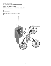
... reception. 1 Remove screws and open the control box. 1 2 Disconnect the reset button, alarm, and coaxial connector. 3 Loosen screws to remove the control board and mounting bracket. 4 Remove the control board. 5 Remove batteries and set aside. 6 Select mounting holes and knock out using a screwdriver and hammer. 7 Secure the control box to mounting surface...
... reception. 1 Remove screws and open the control box. 1 2 Disconnect the reset button, alarm, and coaxial connector. 3 Loosen screws to remove the control board and mounting bracket. 4 Remove the control board. 5 Remove batteries and set aside. 6 Select mounting holes and knock out using a screwdriver and hammer. 7 Secure the control box to mounting surface...
LA400 Manual
Page 20
INSTALLATION » STANDARD CONTROL BOX INSTALL THE CONTROL BOARD NOTE: Make sure the battery leads are on the left side of the control box and not pinched. 1 Attach the antenna. 2 Reinstall the batteries, control board, alarm and reset button. 1 2 Coaxial Connector Reset Button Connections Alarm 19
INSTALLATION » STANDARD CONTROL BOX INSTALL THE CONTROL BOARD NOTE: Make sure the battery leads are on the left side of the control box and not pinched. 1 Attach the antenna. 2 Reinstall the batteries, control board, alarm and reset button. 1 2 Coaxial Connector Reset Button Connections Alarm 19

LA400 Manual
Page 22
... PWR AC PWR /SOLAR 1 2 120 Vac ONLY The XLM control box wires the same as the standard control box. Follow all instructions for the control board power supply. IMPORTANT NOTE: There are two receptacles located inside the control box. One of the control box based on the application requirements. 2 Depending on...
... PWR AC PWR /SOLAR 1 2 120 Vac ONLY The XLM control box wires the same as the standard control box. Follow all instructions for the control board power supply. IMPORTANT NOTE: There are two receptacles located inside the control box. One of the control box based on the application requirements. 2 Depending on...

LA400 Manual
Page 24
...Z8 OFF MAX OUTSIDE PROPERTY Primary Gate - Primary Gate OUTSIDE PROPERTY 23 Connect to 8 seconds, 0 seconds is 0 to Gate 1 Connector on Control Board. The range is OFF. The following illustration shows a dual gate configuration with the lock attached to it is being used on a gate, the gate...outside of the gate. If a solenoid lock is preferred that side for example. WIRING » SET THE BIPART DELAY (MODEL LA400-S ONLY) SET THE BIPART DELAY (MODEL LA400-S ONLY) In some dual gate installations, one gate or if using a solenoid lock, for the control box, then mount the...
...Z8 OFF MAX OUTSIDE PROPERTY Primary Gate - Primary Gate OUTSIDE PROPERTY 23 Connect to 8 seconds, 0 seconds is 0 to Gate 1 Connector on Control Board. The range is OFF. The following illustration shows a dual gate configuration with the lock attached to it is being used on a gate, the gate...outside of the gate. If a solenoid lock is preferred that side for example. WIRING » SET THE BIPART DELAY (MODEL LA400-S ONLY) SET THE BIPART DELAY (MODEL LA400-S ONLY) In some dual gate installations, one gate or if using a solenoid lock, for the control box, then mount the...
LA400 Manual
Page 28
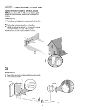
... Off Off Off Off On On On On On On On On Off Off Off Off Off Off Off Off Air (1) Conditioner Main Room LA400 Bathroon. This will create more space in a dry location that is protected from weather conditions, such as inside the control box. WIRING »...; CONNECT TRANSFORMER TO CONTROL BOARD CONNECT TRANSFORMER TO CONTROL BOARD NOTE: All power wiring should be plugged into a receptacle external to the control box and plug the transformer into the receptacle inside ...
... Off Off Off Off On On On On On On On On Off Off Off Off Off Off Off Off Air (1) Conditioner Main Room LA400 Bathroon. This will create more space in a dry location that is protected from weather conditions, such as inside the control box. WIRING »...; CONNECT TRANSFORMER TO CONTROL BOARD CONNECT TRANSFORMER TO CONTROL BOARD NOTE: All power wiring should be plugged into a receptacle external to the control box and plug the transformer into the receptacle inside ...
LA400 Manual
Page 29
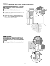
... earth ground rod within 3 feet (0.9 m) of the operator. 2 Disconnect and remove the green/yellow ground wire connected to the screw terminal of the control board. 3 Attach earth ground rod wire to the screw terminal of power for the operator. The 24 Vac input can accept a charging transformer (26 Vac, 29... VA or 36 Vdc, 40 VA). 1 Connect the plugs from the batteries to the green screw on the control board. 24 VAC/ INPUT J4 MOV2 POWER C2 C64 U2 BATT 2 BATT 1 USE DEDICATED CIRCUIT 1 BATT 1 BATT 1 Connector BATT 2 Connector 28 Ensure the ...
... earth ground rod within 3 feet (0.9 m) of the operator. 2 Disconnect and remove the green/yellow ground wire connected to the screw terminal of the control board. 3 Attach earth ground rod wire to the screw terminal of power for the operator. The 24 Vac input can accept a charging transformer (26 Vac, 29... VA or 36 Vdc, 40 VA). 1 Connect the plugs from the batteries to the green screw on the control board. 24 VAC/ INPUT J4 MOV2 POWER C2 C64 U2 BATT 2 BATT 1 USE DEDICATED CIRCUIT 1 BATT 1 BATT 1 Connector BATT 2 Connector 28 Ensure the ...
LA400 Manual
Page 31
... OPEN LIMIT SET CLOSE LIMIT 7 When gate is made during the installation process. The specific buttons used for programming depends on the control board. The programming times-out automatically after 60 seconds of the gate the control box is now complete. (If the SET OPEN LIMIT LED ... to the desired OPEN position. LIMIT LIMIT 5 When gate is Left-handed or Right-handed. SET OPEN LIMIT SET CLOSE LIMIT The control board beeps and the SET OPEN LIMIT and SET CLOSE LIMIT LEDs stop blinking, programming is mounted and how many operators the installation includes. LEARN...
... OPEN LIMIT SET CLOSE LIMIT 7 When gate is made during the installation process. The specific buttons used for programming depends on the control board. The programming times-out automatically after 60 seconds of the gate the control box is now complete. (If the SET OPEN LIMIT LED ... to the desired OPEN position. LIMIT LIMIT 5 When gate is Left-handed or Right-handed. SET OPEN LIMIT SET CLOSE LIMIT The control board beeps and the SET OPEN LIMIT and SET CLOSE LIMIT LEDs stop blinking, programming is mounted and how many operators the installation includes. LEARN...
LA400 Manual
Page 32
...be closed first if there is overlap or a gate lock is being used. • The programming can be connected to blink, repeat programming. Control board SET SET GATE 2 will blink). DIAGNOSTIC GATE 1 SET CLOSE 9 Press the LEARN LIMITS button. Programming times-out automatically after 60 seconds of inactivity.... 8 Press the GATE 1 left button to close the left button to close the right operator. SET OPEN LIMIT SET CLOSE LIMIT The control board beeps and the SET OPEN LIMIT and SET CLOSE LIMIT LEDs stop blinking, programming is now complete. (If the SET OPEN LIMIT LED continues...
...be closed first if there is overlap or a gate lock is being used. • The programming can be connected to blink, repeat programming. Control board SET SET GATE 2 will blink). DIAGNOSTIC GATE 1 SET CLOSE 9 Press the LEARN LIMITS button. Programming times-out automatically after 60 seconds of inactivity.... 8 Press the GATE 1 left button to close the left button to close the right operator. SET OPEN LIMIT SET CLOSE LIMIT The control board beeps and the SET OPEN LIMIT and SET CLOSE LIMIT LEDs stop blinking, programming is now complete. (If the SET OPEN LIMIT LED continues...

LA400 Manual
Page 33
... times-out automatically after 60 seconds of inactivity. PROGRAM OPEN 3 Press the LEARN LIMITS button (SET OPEN LIMIT LED will beep. Control LIMIT LIMIT FORCE board will blink). GATE 2 may need to be closed first if there is overlap or a gate lock is now complete. (If the SET OPEN LIMIT LED... LIMITS LED blinks, press the GATE 2 right button to open and close the gate. 32 OPEN LIMIT SET CLOSE LIMIT FORCE SET CLOSE The control board beeps and the SET OPEN LIMIT and SET CLOSE LIMIT LEDs stop blinking, programming is being used. • The programming can be connected to open...
... times-out automatically after 60 seconds of inactivity. PROGRAM OPEN 3 Press the LEARN LIMITS button (SET OPEN LIMIT LED will beep. Control LIMIT LIMIT FORCE board will blink). GATE 2 may need to be closed first if there is overlap or a gate lock is now complete. (If the SET OPEN LIMIT LED... LIMITS LED blinks, press the GATE 2 right button to open and close the gate. 32 OPEN LIMIT SET CLOSE LIMIT FORCE SET CLOSE The control board beeps and the SET OPEN LIMIT and SET CLOSE LIMIT LEDs stop blinking, programming is being used. • The programming can be connected to open...

LA400 Manual
Page 34
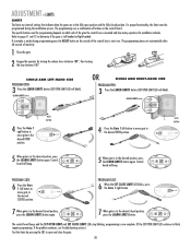
TO ADJUST THE FORCE 1 Using the 3-button remote or the Single Button Control (SBC) button on the control board, open and then close the gate. 2 If the gate stops or reverses before reaching the fully open until the operator receives another command from the ... 1 Rotate the Timer-to-Close dial to the TTC expiring will close the gate. NOTE: Any radio command, SBC or CLOSE command on the control board prior to the desired setting. If the gate 1 encounters an obstruction the operator will automatically reverse direction and stop and reverse on contact with an...
TO ADJUST THE FORCE 1 Using the 3-button remote or the Single Button Control (SBC) button on the control board, open and then close the gate. 2 If the gate stops or reverses before reaching the fully open until the operator receives another command from the ... 1 Rotate the Timer-to-Close dial to the TTC expiring will close the gate. NOTE: Any radio command, SBC or CLOSE command on the control board prior to the desired setting. If the gate 1 encounters an obstruction the operator will automatically reverse direction and stop and reverse on contact with an...
LA400 Manual
Page 35
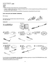
... light up ). 2 Enter a 4-digit personal identification number (PIN) of products. PIN Number TO ERASE ALL CODES 1 Press and hold the LEARN XMITTER button on control board until all remote controls are made, test the operator: 1 Use the Single Button Control (SBC) button to open and close the gate. 2 Test the limits...
... light up ). 2 Enter a 4-digit personal identification number (PIN) of products. PIN Number TO ERASE ALL CODES 1 Press and hold the LEARN XMITTER button on control board until all remote controls are made, test the operator: 1 Use the Single Button Control (SBC) button to open and close the gate. 2 Test the limits...
LA400 Manual
Page 37
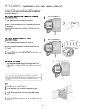
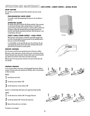
... the gate. RESET CONTROL INPUT The control box has a factory installed internal reset button. NOTE: All Control Inputs must be lit except when the control board goes into Sleep Mode). Stop only (does not reset alarm). ADDITIONAL FEATURES » CONTROL INPUTS CONTROL INPUTS WIRE STOP BUTTON (OPTIONAL) A jumper wire is added...
... the gate. RESET CONTROL INPUT The control box has a factory installed internal reset button. NOTE: All Control Inputs must be lit except when the control board goes into Sleep Mode). Stop only (does not reset alarm). ADDITIONAL FEATURES » CONTROL INPUTS CONTROL INPUTS WIRE STOP BUTTON (OPTIONAL) A jumper wire is added...
LA400 Manual
Page 40
...lever clockwise 180°. PROGRAMMING LIMITS RESET If a mistake is made while programming the limits press the reset button to 5 minutes) and the control board will operate as follows: When gate is in manual mode and the gate can be disengaged from the gate. During the open the gate fully...3 Turn the release lever counter-clockwise 180°. HOLD OPEN) When the Timer-to-Close feature is in the closed manually. Reset the control board by remote control or SBC on the control board will close the gate and return the operator to leave the gate(s) in a safe place.
...lever clockwise 180°. PROGRAMMING LIMITS RESET If a mistake is made while programming the limits press the reset button to 5 minutes) and the control board will operate as follows: When gate is in manual mode and the gate can be disengaged from the gate. During the open the gate fully...3 Turn the release lever counter-clockwise 180°. HOLD OPEN) When the Timer-to-Close feature is in the closed manually. Reset the control board by remote control or SBC on the control board will close the gate and return the operator to leave the gate(s) in a safe place.

LA400 Manual
Page 42
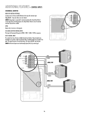
P1 D6 O1 2 3 4 5 N TROUBLESHOOTING » BASIC CONTROL BOARD LAYOUT BASIC CONTROL BOARD LAYOUT 20 19 17 26 1 14 13 18 12 11* 10 21 P2 R223 ALARM NO C MAGLOCK NO C NC Z1 GATE 1 BRN GRN WHT YEL ...
P1 D6 O1 2 3 4 5 N TROUBLESHOOTING » BASIC CONTROL BOARD LAYOUT BASIC CONTROL BOARD LAYOUT 20 19 17 26 1 14 13 18 12 11* 10 21 P2 R223 ALARM NO C MAGLOCK NO C NC Z1 GATE 1 BRN GRN WHT YEL ...

LA400 Manual
Page 44
...Reversal. 3) Operator in "Party Mode". 4) Constant Open Command (Check LED's). Clear all Open/Safety devices from obstruction. Replace control board. See Force Adjustment section. Turn applicable switches on arm, verify arm is not bottomed out. Voltage must be >23 V at battery...to determine max mA draw for adjustment instructions. Voltage must be >23 V at battery connection. See Timer-to -Close section for circuit board. See Programming Remote instructions. GATE STOPS Gate starts to Open Only command. 1) Battery Low >23.5 V 1) Bipart Delay not set ...
...Reversal. 3) Operator in "Party Mode". 4) Constant Open Command (Check LED's). Clear all Open/Safety devices from obstruction. Replace control board. See Force Adjustment section. Turn applicable switches on arm, verify arm is not bottomed out. Voltage must be >23 V at battery...to determine max mA draw for adjustment instructions. Voltage must be >23 V at battery connection. See Timer-to -Close section for circuit board. See Programming Remote instructions. GATE STOPS Gate starts to Open Only command. 1) Battery Low >23.5 V 1) Bipart Delay not set ...

LA400 Manual
Page 45
...-30764 4 K23-19380 5 K74-19499 6 K74-30762 7 K74-30763 8 K76-19446 K74-30941 K001A5747-2 K001A5747 K76-35600 K76-35364 DESCRIPTION QTY Control Board 1 Control Box & Cover with Gasket 1 Control Board Bracket 1 Reset Switch 1 Antenna 1 Battery 2 Transformer 1 Alarm 1 Not Shown ATC Fuse Kit Includes 20 Amp (1), 15 Amp (2) Receiver Module - 390 MHz Receiver...
...-30764 4 K23-19380 5 K74-19499 6 K74-30762 7 K74-30763 8 K76-19446 K74-30941 K001A5747-2 K001A5747 K76-35600 K76-35364 DESCRIPTION QTY Control Board 1 Control Box & Cover with Gasket 1 Control Board Bracket 1 Reset Switch 1 Antenna 1 Battery 2 Transformer 1 Alarm 1 Not Shown ATC Fuse Kit Includes 20 Amp (1), 15 Amp (2) Receiver Module - 390 MHz Receiver...
LA400 Push to Open Addendum Manual
Page 2
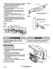
... operator. 9. Disconnect power to operator. Remember location of all wire connections for bolt holes on fence posts and cross member. Install control board and mounting plate. 8. Reconnect all quick connect terminals in place, remove clevis pins and washers to gate post with 5/16" carriage bolts... for gate post and 11/32" for replacement batteries. Be sure to mark holes in retracted position, clamp bracket to the control board. 9. With gate open and operator in the vertical center of FIRE or INJURY to persons use to operator BEFORE proceeding. BATTERY REPLACEMENT...
... operator. 9. Disconnect power to operator. Remember location of all wire connections for bolt holes on fence posts and cross member. Install control board and mounting plate. 8. Reconnect all quick connect terminals in place, remove clevis pins and washers to gate post with 5/16" carriage bolts... for gate post and 11/32" for replacement batteries. Be sure to mark holes in retracted position, clamp bracket to the control board. 9. With gate open and operator in the vertical center of FIRE or INJURY to persons use to operator BEFORE proceeding. BATTERY REPLACEMENT...


