3900PLD Manual
Page 2
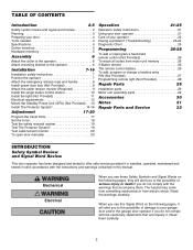
... 26 To add, program or change a keyless entry PIN (Not Provided 27 Programming remote light (Not Provided 28 Repair Parts 29 Installation parts 29 Motor unit assembly parts 29 Accessories 30 Notes 31 Repair Parts and Service 32 INTRODUCTION Safety Symbol Review and Signal Word Review This door operator has been designed and tested...
... 26 To add, program or change a keyless entry PIN (Not Provided 27 Programming remote light (Not Provided 28 Repair Parts 29 Installation parts 29 Motor unit assembly parts 29 Accessories 30 Notes 31 Repair Parts and Service 32 INTRODUCTION Safety Symbol Review and Signal Word Review This door operator has been designed and tested...

3900PLD Manual
Page 5
... (2) Drywall Anchor (2) Drywall Anchor (Screw-In) (2) Handle Rope Insulated Staples (30) 5 If anything is packaged in one carton which contains the motor unit and the parts illustrated below. Note that accessories will depend on the model purchased.
... (2) Drywall Anchor (2) Drywall Anchor (Screw-In) (2) Handle Rope Insulated Staples (30) 5 If anything is packaged in one carton which contains the motor unit and the parts illustrated below. Note that accessories will depend on the model purchased.
3900PLD Manual
Page 7
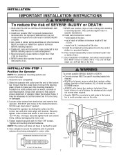
... operator. Door MUST reverse on inside of SEVERE INJURY or DEATH: 1. READ AND FOLLOW ALL INSTALLATION WARNINGS AND INSTRUCTIONS. 2. Loosen collar screws from ALL moving parts of operator. Snug collar screws to make sure the mounting bracket is too long or damaged. 3. WARNING INSTALLATION IMPORTANT INSTALLATION INSTRUCTIONS WARNING To reduce the...
... operator. Door MUST reverse on inside of SEVERE INJURY or DEATH: 1. READ AND FOLLOW ALL INSTALLATION WARNINGS AND INSTRUCTIONS. 2. Loosen collar screws from ALL moving parts of operator. Snug collar screws to make sure the mounting bracket is too long or damaged. 3. WARNING INSTALLATION IMPORTANT INSTALLATION INSTRUCTIONS WARNING To reduce the...

3900PLD Manual
Page 10
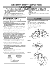
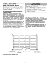
... placards to 24 VOLT low voltage wires. The installation surface must be smooth and flat. 3. To prevent possible SERIOUS INJURY or DEATH from ALL moving parts of children at least 5' (1.5 m) above the ground. INSTALLATION STEP 5 Install the Single Button Control Station 1. Remove the control station cover. 2. Fasten the control station to...
... placards to 24 VOLT low voltage wires. The installation surface must be smooth and flat. 3. To prevent possible SERIOUS INJURY or DEATH from ALL moving parts of children at least 5' (1.5 m) above the ground. INSTALLATION STEP 5 Install the Single Button Control Station 1. Remove the control station cover. 2. Fasten the control station to...
3900PLD Manual
Page 11
... outlet. 9. Wind any excess cord around cord retainer on each side of an electrical outlet so that the cord and light are away from moving parts. 3. Install the hinge and latch clips. IMPORTANT SAFETY INSTRUCTIONS WARNING To reduce the risk of electric shock. 2. This portable luminaire has a polarized plug (one way...
... outlet. 9. Wind any excess cord around cord retainer on each side of an electrical outlet so that the cord and light are away from moving parts. 3. Install the hinge and latch clips. IMPORTANT SAFETY INSTRUCTIONS WARNING To reduce the risk of electric shock. 2. This portable luminaire has a polarized plug (one way...

3900PLD Manual
Page 12
...) of electric shock, your local code, refer to the 7/8" hole. Be sure the operator is required by your operator has a grounding type plug with moving parts. • Reinstall the cover. To make it fit outlet. Reinstall operator to install the proper outlet. PERMANENT WIRING CONNECTION RIGHT WRONG If permanent wiring is...
...) of electric shock, your local code, refer to the 7/8" hole. Be sure the operator is required by your operator has a grounding type plug with moving parts. • Reinstall the cover. To make it fit outlet. Reinstall operator to install the proper outlet. PERMANENT WIRING CONNECTION RIGHT WRONG If permanent wiring is...

3900PLD Manual
Page 13
... Cord 475LM Standby Power System Connector 13 INSTALLATION STEP 8 Mount the Standby Power Unit (SPU) (Not Provided) If the optional 475LM Standby Power Unit is part of this installation it should be installed at this time. • The SPU can be mounted to either the ceiling or a wall within 3' (.9 m) of the...
... Cord 475LM Standby Power System Connector 13 INSTALLATION STEP 8 Mount the Standby Power Unit (SPU) (Not Provided) If the optional 475LM Standby Power Unit is part of this installation it should be installed at this time. • The SPU can be mounted to either the ceiling or a wall within 3' (.9 m) of the...
3900PLD Manual
Page 14
... path must be disabled. • Install the safety reversing sensor so beam is closing door: • Correctly connect and align the safety reversing sensor. No part of its electronic beam. Either can be securely fastened to mount the units on the wall, the brackets must be installed inside the garage 14...
... path must be disabled. • Install the safety reversing sensor so beam is closing door: • Correctly connect and align the safety reversing sensor. No part of its electronic beam. Either can be securely fastened to mount the units on the wall, the brackets must be installed inside the garage 14...
3900PLD Manual
Page 26
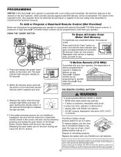
... with your operator. If this occurs, the door can be programmed to operate other Security✚® door operators. THERE ARE NO OTHER USER SERVICEABLE PARTS. PROGRAMMING NOTICE: If this Security✚® door operator is subject to the following two conditions: (1) this device may cause undesired operation. 26 Additional buttons...
... with your operator. If this occurs, the door can be programmed to operate other Security✚® door operators. THERE ARE NO OTHER USER SERVICEABLE PARTS. PROGRAMMING NOTICE: If this Security✚® door operator is subject to the following two conditions: (1) this device may cause undesired operation. 26 Additional buttons...
3900PLD Manual
Page 29
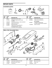
...monitor Mounting bracket Safety sensor kit (receiving and sending eyes) with 3' (.9 m) 2-conductor bell wire attached KEY NO. 7 8 PART NO. 41A6388 41A5266-1 41A6298 114A3593 DESCRIPTION Collar with set screws (2) Safety sensor brackets (2) NOT SHOWN Installation hardware bag (includes hardware ...listed on page 5) Owner's manual Motor Unit Assembly Parts 2 1 6 5 3 4 KEY NO. 1 2 3 PART NO. 41DJ001 41A6408 41C168 DESCRIPTION Logic board complete with plate Absolute Encoder System Transformer KEY NO. 4 5 6 PART NO. 41A6095 41B122 41A6348-3 DESCRIPTION Motor with bracket Power...
...monitor Mounting bracket Safety sensor kit (receiving and sending eyes) with 3' (.9 m) 2-conductor bell wire attached KEY NO. 7 8 PART NO. 41A6388 41A5266-1 41A6298 114A3593 DESCRIPTION Collar with set screws (2) Safety sensor brackets (2) NOT SHOWN Installation hardware bag (includes hardware ...listed on page 5) Owner's manual Motor Unit Assembly Parts 2 1 6 5 3 4 KEY NO. 1 2 3 PART NO. 41DJ001 41A6408 41C168 DESCRIPTION Logic board complete with plate Absolute Encoder System Transformer KEY NO. 4 5 6 PART NO. 41A6095 41B122 41A6348-3 DESCRIPTION Motor with bracket Power...

3900PLD Manual
Page 32
... and you will be billed accordingly. Technical Support Group 6050 S. SIMPLY DIAL OUR TOLL FREE NUMBER: 1-800-528-2806 www.liftmaster.com For professional installation, parts and service, contact your area. Look for him in the Yellow Pages, or call our Service number for a list of... dealers in your local LIFTMASTER/CHAMBERLAIN dealer. LIFTMASTER® SERVICE IS ON CALL OUR LARGE SERVICE ORGANIZATION SPANS AMERICA INSTALLATION AND SERVICE ...
... and you will be billed accordingly. Technical Support Group 6050 S. SIMPLY DIAL OUR TOLL FREE NUMBER: 1-800-528-2806 www.liftmaster.com For professional installation, parts and service, contact your area. Look for him in the Yellow Pages, or call our Service number for a list of... dealers in your local LIFTMASTER/CHAMBERLAIN dealer. LIFTMASTER® SERVICE IS ON CALL OUR LARGE SERVICE ORGANIZATION SPANS AMERICA INSTALLATION AND SERVICE ...


