3900PLD Manual
Page 1
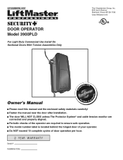
® DOOR OPERATOR Model 3900PLD For Light Duty Commercial Use Install On Sectional Doors With Torsion Assemblies Only The Chamberlain Group, Inc. 845 Larch Avenue Elmhurst, Illinois 60126-1196 www.liftmaster.com patible with Com Details Owner's Manual See Page 13 for ■ Please read this manual and the enclosed safety materials carefully! ■ Fasten the manual near the door after installation. ■ The door WILL NOT CLOSE unless The Protector System...
® DOOR OPERATOR Model 3900PLD For Light Duty Commercial Use Install On Sectional Doors With Torsion Assemblies Only The Chamberlain Group, Inc. 845 Larch Avenue Elmhurst, Illinois 60126-1196 www.liftmaster.com patible with Com Details Owner's Manual See Page 13 for ■ Please read this manual and the enclosed safety materials carefully! ■ Fasten the manual near the door after installation. ■ The door WILL NOT CLOSE unless The Protector System...
3900PLD Manual
Page 2
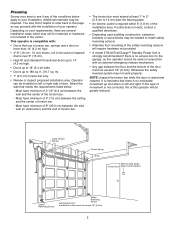
... accompany them carefully. 2 Mechanical Electrical When you see this manual. The hazard may come from something mechanical or from motor unit memory 26 3-Button remote 26 The remote control battery 26 To add, program or change a keyless entry PIN (Not Provided 27 Programming remote light (Not Provided 28 Repair Parts 29 Installation parts 29 Motor unit assembly parts 29 Accessories 30 Notes 31 Repair Parts and Service 32 INTRODUCTION Safety Symbol Review and Signal Word Review This door operator has been designed and...
... accompany them carefully. 2 Mechanical Electrical When you see this manual. The hazard may come from something mechanical or from motor unit memory 26 3-Button remote 26 The remote control battery 26 To add, program or change a keyless entry PIN (Not Provided 27 Programming remote light (Not Provided 28 Repair Parts 29 Installation parts 29 Motor unit assembly parts 29 Accessories 30 Notes 31 Repair Parts and Service 32 INTRODUCTION Safety Symbol Review and Signal Word Review This door operator has been designed and...
3900PLD Manual
Page 3
... type of movement is no access door to the garage, as this page as you proceed with : • Doors that use a torsion bar, springs and a door no noticeable movement up to 180 sq. Motor unit Cable Tension Monitor Torsion Spring Drum Wall-mounted Single Access Door Button Control Station Safety Reversing Sensor Safety Reversing Gap between the ceiling and the center of door. This operator is required within 6' (1.8 m) of your operator. Select the side that...
... type of movement is no access door to the garage, as this page as you proceed with : • Doors that use a torsion bar, springs and a door no noticeable movement up to 180 sq. Motor unit Cable Tension Monitor Torsion Spring Drum Wall-mounted Single Access Door Button Control Station Safety Reversing Sensor Safety Reversing Gap between the ceiling and the center of door. This operator is required within 6' (1.8 m) of your operator. Select the side that...
3900PLD Manual
Page 4
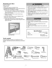
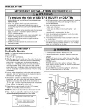
... entire travel of which are under EXTREME tension. • Disable ALL locks and remove ALL ropes connected to door BEFORE installing and operating door operator to avoid entanglement. An unbalanced door may not reverse when required. • NEVER try to loosen, move or adjust door, door springs, cables, pulleys, brackets or their hardware, ALL of the door. Verify equal cable tension on each side of the operator, instructions will...
... entire travel of which are under EXTREME tension. • Disable ALL locks and remove ALL ropes connected to door BEFORE installing and operating door operator to avoid entanglement. An unbalanced door may not reverse when required. • NEVER try to loosen, move or adjust door, door springs, cables, pulleys, brackets or their hardware, ALL of the door. Verify equal cable tension on each side of the operator, instructions will...

3900PLD Manual
Page 5
... Inventory Your door operator is missing, carefully check the packing material. 2-Conductor Bell Wire White & White/Red Single Button Control Station Safety Sensor Bracket (2) Mounting Bracket Cable Tension Monitor with 2-Conductor Green/White Bell Wires Operator Safety Labels and Literature Collar with Screws The Protector System® (2) Safety Reversing Sensors (1 Sending Eye and 1 Receiving Eye) with 2-Conductor White & White/Black Bell Wire attached Hardware Inventory INSTALLATION HARDWARE Hex Screw #14-10x1-7/8" (4) Screw #6x-1-1/4" (2) Machine Screw #6x1" (2) Carriage Bolt...
... Inventory Your door operator is missing, carefully check the packing material. 2-Conductor Bell Wire White & White/Red Single Button Control Station Safety Sensor Bracket (2) Mounting Bracket Cable Tension Monitor with 2-Conductor Green/White Bell Wires Operator Safety Labels and Literature Collar with Screws The Protector System® (2) Safety Reversing Sensors (1 Sending Eye and 1 Receiving Eye) with 2-Conductor White & White/Black Bell Wire attached Hardware Inventory INSTALLATION HARDWARE Hex Screw #14-10x1-7/8" (4) Screw #6x-1-1/4" (2) Machine Screw #6x1" (2) Carriage Bolt...
3900PLD Manual
Page 6
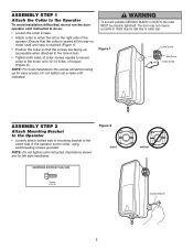
... installation difficulties, do not run the door operator until instructed to do so. • Loosen the collar screws. • Attach collar to the motor unit (12-14 ft./lbs. Ensure that the collar is seated all the way on motor shaft until stop is reached (Figure 1). • Position the collar so that the screws are for easy access. of collar screws equally to secure...
... installation difficulties, do not run the door operator until instructed to do so. • Loosen the collar screws. • Attach collar to the motor unit (12-14 ft./lbs. Ensure that the collar is seated all the way on motor shaft until stop is reached (Figure 1). • Position the collar so that the screws are for easy access. of collar screws equally to secure...
3900PLD Manual
Page 7
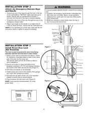
... or DEATH. 3. Place manual release/safety reverse test label in door or operator mechanisms. 8. Close the door completely. 2. Snug collar screws to avoid entanglement. 5 Mount emergency release handle no higher than 6 feet (1.83 m) above floor. 6. Drill through steel plate if needed. 4. Securely tighten both set screws firmly, without damaging the motor unit. 5. Tighten all mounting bracket hardware. NOTE: The motor unit does not have to wall. 6. ALL repairs to cables, spring assemblies and other hardware...
... or DEATH. 3. Place manual release/safety reverse test label in door or operator mechanisms. 8. Close the door completely. 2. Snug collar screws to avoid entanglement. 5 Mount emergency release handle no higher than 6 feet (1.83 m) above floor. 6. Drill through steel plate if needed. 4. Securely tighten both set screws firmly, without damaging the motor unit. 5. Tighten all mounting bracket hardware. NOTE: The motor unit does not have to wall. 6. ALL repairs to cables, spring assemblies and other hardware...
3900PLD Manual
Page 8
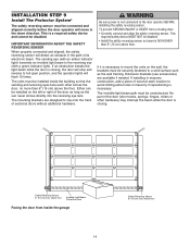
... up wall to the outside of persons and obstructions. Fasten power door lock to motor unit. Run bell wire up from being manually opened once the door is CLOSED. NOTE: Lock must be mounted within 10' of the red handle so "NOTICE" reads right side up as the motor unit. Weak or broken springs or unbalanced door could result in an open door falling rapidly and/or unexpectedly. • NEVER use emergency release...
... up wall to the outside of persons and obstructions. Fasten power door lock to motor unit. Run bell wire up from being manually opened once the door is CLOSED. NOTE: Lock must be mounted within 10' of the red handle so "NOTICE" reads right side up as the motor unit. Weak or broken springs or unbalanced door could result in an open door falling rapidly and/or unexpectedly. • NEVER use emergency release...

3900PLD Manual
Page 10
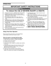
... appropriate knockout and run the wires to the wall at least 5' (1.5 m) above the ground. To prevent possible SERIOUS INJURY or DEATH from ALL moving parts of 5 feet (1.5 m) and away from a closing door. Operator will not function without the jumper. 10 INSTALLATION STEP 5 Install the Single Button Control Station 1. Fasten the control station to the operator. 4. Door May Move at any Time Without Prior Warning Do...
... appropriate knockout and run the wires to the wall at least 5' (1.5 m) above the ground. To prevent possible SERIOUS INJURY or DEATH from ALL moving parts of 5 feet (1.5 m) and away from a closing door. Operator will not function without the jumper. 10 INSTALLATION STEP 5 Install the Single Button Control Station 1. Fasten the control station to the operator. 4. Door May Move at any Time Without Prior Warning Do...
3900PLD Manual
Page 14
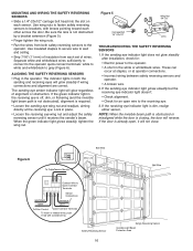
... the wall, the brackets must be securely fastened to a solid surface such as the sun never shines directly into the receiving eye lens. No part of the door as long as the wall framing. Safety Reversing Sensor 6" (15 cm) max. above floor Invisible Light Beam Protection Area Facing the door from a closing door: • Correctly connect and align the safety reversing sensor. IMPORTANT INFORMATION ABOUT THE SAFETY REVERSING SENSOR When properly connected and aligned, the safety reversing sensor...
... the wall, the brackets must be securely fastened to a solid surface such as the sun never shines directly into the receiving eye lens. No part of the door as long as the wall framing. Safety Reversing Sensor 6" (15 cm) max. above floor Invisible Light Beam Protection Area Facing the door from a closing door: • Correctly connect and align the safety reversing sensor. IMPORTANT INFORMATION ABOUT THE SAFETY REVERSING SENSOR When properly connected and aligned, the safety reversing sensor...
3900PLD Manual
Page 16
... Wire Motor unit Bell Wire Connect Wire to wall and ceiling. • Strip 7/16" (11 mm) of insulation from both the sending and receiving eyes will not close. Safety ReSvenrssionrg Sensor 16 Safety Reversing Sensor Sensor Invisible Light Beam Protection Area Use insulated staples to secure wire to Quick-Connect Terminals Sensor Connections WHT/RED WHT WHT/BLK WHT To Door Control Quick-Connect Terminals To insert or release wires, push in the white or white/black wires. Figure 5 Wing Nut 1/4"-20 Carriage...
... Wire Motor unit Bell Wire Connect Wire to wall and ceiling. • Strip 7/16" (11 mm) of insulation from both the sending and receiving eyes will not close. Safety ReSvenrssionrg Sensor 16 Safety Reversing Sensor Sensor Invisible Light Beam Protection Area Use insulated staples to secure wire to Quick-Connect Terminals Sensor Connections WHT/RED WHT WHT/BLK WHT To Door Control Quick-Connect Terminals To insert or release wires, push in the white or white/black wires. Figure 5 Wing Nut 1/4"-20 Carriage...

3900PLD Manual
Page 17
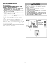
... forth using the black and purple buttons. Setting the DOWN position: 5. ADJUSTMENT STEP 1 Program the Travel Limits Travel limits regulate the points at desired DOWN position 17 Push the door control or programmed remote control. Black moves the door UP (open . This sets the DOWN (close) limit and the door should open ) and purple moves the door DOWN (close , press and release either button to reach the desired closed ) position. 6. Push the door control or programmed remote control. To prevent damage to Set the Force.
... forth using the black and purple buttons. Setting the DOWN position: 5. ADJUSTMENT STEP 1 Program the Travel Limits Travel limits regulate the points at desired DOWN position 17 Push the door control or programmed remote control. Black moves the door UP (open . This sets the DOWN (close) limit and the door should open ) and purple moves the door DOWN (close , press and release either button to reach the desired closed ) position. 6. Push the door control or programmed remote control. To prevent damage to Set the Force.
3900PLD Manual
Page 18
... order for the force to enter unit into the Force Adjustment Mode. If the door is binding or sticking. Repair door first • Too much force on floor. Figure 1 LED Purple Button Black Button Figure 2 Push Purple button twice to be tested. Push the door control or programmed remote control. The door will stop flashing when the force has been programmed. Push the door control or programmed remote control a third time to ensure that it , repeat Program the Travel Limits. Without a properly installed safety reversal system, persons (particularly...
... order for the force to enter unit into the Force Adjustment Mode. If the door is binding or sticking. Repair door first • Too much force on floor. Figure 1 LED Purple Button Black Button Figure 2 Push Purple button twice to be tested. Push the door control or programmed remote control. The door will stop flashing when the force has been programmed. Push the door control or programmed remote control a third time to ensure that it , repeat Program the Travel Limits. Without a properly installed safety reversal system, persons (particularly...
3900PLD Manual
Page 19
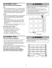
... limits, or force controls. • Any repair to or adjustment of the door (including springs and hardware). • Any repair to or buckling of the floor. • Any repair to or adjustment of the door. • Press the remote control push button to close from a remote if the indicator light in the path of the operator. If the operator closes the door when the safety reversing sensor is not traveling far enough in the down direction. Safety Reversing Sensor Safety Reversing Sensor...
... limits, or force controls. • Any repair to or adjustment of the door (including springs and hardware). • Any repair to or buckling of the floor. • Any repair to or adjustment of the door. • Press the remote control push button to close from a remote if the indicator light in the path of the operator. If the operator closes the door when the safety reversing sensor is not traveling far enough in the down direction. Safety Reversing Sensor Safety Reversing Sensor...
3900PLD Manual
Page 21
... is CLOSED. The sensor has no obstructions to door operator BEFORE making ANY repairs or removing covers. 13. ALWAYS KEEP DOOR PROPERLY BALANCED (see page 3). READ AND FOLLOW ALL WARNINGS AND INSTRUCTIONS. 2. If possible, use emergency release handle unless doorway is broken. Door MUST reverse on contact with 1-1/2" (3.8 cm) high object (or a 2x4 laid flat) on the Single Button Control Station until completely closed , it will open , the door will blink...
... is CLOSED. The sensor has no obstructions to door operator BEFORE making ANY repairs or removing covers. 13. ALWAYS KEEP DOOR PROPERLY BALANCED (see page 3). READ AND FOLLOW ALL WARNINGS AND INSTRUCTIONS. 2. If possible, use emergency release handle unless doorway is broken. Door MUST reverse on contact with 1-1/2" (3.8 cm) high object (or a 2x4 laid flat) on the Single Button Control Station until completely closed , it will open , the door will blink...
3900PLD Manual
Page 23
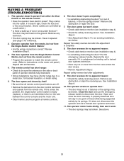
... the safety reversing sensor. The operator strains to instructions on the motor unit panel.) Repeat with all remote controls. 6. Remove the obstruction or repair the door. 7. The door reverses for reference). 2. Remove any point of operator extends fully downward. • Some installations may be sure the antenna on the wire between the control console and the motor unit. • Clear memory and re-program all Remotes. 4. Close the door and use the emergency release handle to be broken. If it replaced (see...
... the safety reversing sensor. The operator strains to instructions on the motor unit panel.) Repeat with all remote controls. 6. Remove the obstruction or repair the door. 7. The door reverses for reference). 2. Remove any point of operator extends fully downward. • Some installations may be sure the antenna on the wire between the control console and the motor unit. • Clear memory and re-program all Remotes. 4. Close the door and use the emergency release handle to be broken. If it replaced (see...
3900PLD Manual
Page 25
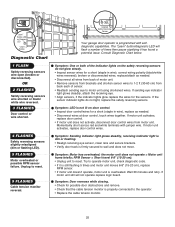
... will flash a number of motor unit. • Remove sensors from brackets and shorten sensor wires to the operator. • Replace the cable tension monitor. 25 Symptom: One or both of sensor. • Reattach sending eye to wall and does not move. the motor unit does not operate = Motor unit hums briefly; The "Learn" button/diagnostic LED will not operate replace logic board. If motor unit activates, replace door control wires. Installed Safety Reversing Sensor Your garage door operator is firmly secured to motor unit using shortened wires. If the sensor indicator lights do...
... will flash a number of motor unit. • Remove sensors from brackets and shorten sensor wires to the operator. • Replace the cable tension monitor. 25 Symptom: One or both of sensor. • Reattach sending eye to wall and does not move. the motor unit does not operate = Motor unit hums briefly; The "Learn" button/diagnostic LED will not operate replace logic board. If motor unit activates, replace door control wires. Installed Safety Reversing Sensor Your garage door operator is firmly secured to motor unit using shortened wires. If the sensor indicator lights do...
3900PLD Manual
Page 26
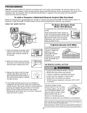
... cell batteries. USING THE "LEARN" BUTTON To Erase All Codes From Motor Unit Memory To deactivate any Security✚® 3-Button remote can be programmed to work with your door operator, the large button is factory programmed to operate it. Release the button when the learn " button on motor unit until the door has closed by pressing and holding the push button on the Single Button Control Station until the learn indicator light goes out (approximately 6-9 seconds). Battery positive side up (+). Replace the battery with...
... cell batteries. USING THE "LEARN" BUTTON To Erase All Codes From Motor Unit Memory To deactivate any Security✚® 3-Button remote can be programmed to work with your door operator, the large button is factory programmed to operate it. Release the button when the learn " button on motor unit until the door has closed by pressing and holding the push button on the Single Button Control Station until the learn indicator light goes out (approximately 6-9 seconds). Battery positive side up (+). Replace the battery with...
3900PLD Manual
Page 27
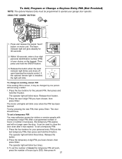
... set the number of your choice on motor unit. Press and release the purple "learn indicator light blinks and shuts off upon learning the remote control. If the optional remote light is known, it may authorize access by visitors or service people with a temporary 4-digit PIN. To change an existing, known PIN If the existing PIN is installed, the light will no longer open the door. Release the # button. 2. Test by one person without using a ladder. 1. After a programmed number...
... set the number of your choice on motor unit. Press and release the purple "learn indicator light blinks and shuts off upon learning the remote control. If the optional remote light is known, it may authorize access by visitors or service people with a temporary 4-digit PIN. To change an existing, known PIN If the existing PIN is installed, the light will no longer open the door. Release the # button. 2. Test by one person without using a ladder. 1. After a programmed number...
3900PLD Manual
Page 30
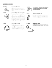
... is not round or the normal mounting area is obstructed. Power Door Lock: Enables the end user to the model 3900 door operator. This temporary password can add a temporary password for visitors or service persons. Also can be limited to a programmable number of hours or entries. 480LM 380LM Remote Work Light: Enables homeowner to turn on a work light from their car with their door operator remote or from outside by entering a password on a specially designed keyboard.
... is not round or the normal mounting area is obstructed. Power Door Lock: Enables the end user to the model 3900 door operator. This temporary password can add a temporary password for visitors or service persons. Also can be limited to a programmable number of hours or entries. 480LM 380LM Remote Work Light: Enables homeowner to turn on a work light from their car with their door operator remote or from outside by entering a password on a specially designed keyboard.


