Service Manual
Page 8
...cooling fan 3-76 LVPS card assembly 3-76 HVPS card assembly 3-76 System card assembly 3-77 Control 3-77 Printhead control 3-77 Rotation of printhead motor 3-77 Determination of printhead ready 3-77 Printhead reference value 3-77 Fuser control 3-77 Fuser control method 3-77 Fuser lamp on/off control 3-77 Fuser ...(media low 3-87 Sensor (pass-thru 3-87 Media transport path 3-89 Model T650 paper path, rolls, and sensors 3-89 Models T652 and T654 paper path, rolls, and sensors 3-90 Functions of main components 3-90 Media tray assembly 3-90 Rear media guide 3-90 Side guide 3-90...
...cooling fan 3-76 LVPS card assembly 3-76 HVPS card assembly 3-76 System card assembly 3-77 Control 3-77 Printhead control 3-77 Rotation of printhead motor 3-77 Determination of printhead ready 3-77 Printhead reference value 3-77 Fuser control 3-77 Fuser control method 3-77 Fuser lamp on/off control 3-77 Fuser ...(media low 3-87 Sensor (pass-thru 3-87 Media transport path 3-89 Model T650 paper path, rolls, and sensors 3-89 Models T652 and T654 paper path, rolls, and sensors 3-90 Functions of main components 3-90 Media tray assembly 3-90 Rear media guide 3-90 Side guide 3-90...
Service Manual
Page 9
...sensitive parts 4-1 Adjustments 4-2 Polygon and Oscillating printhead mechanical registration adjustment 4-2 Oscillating printhead assembly electronic adjustment 4-3 Alignment assembly adjustment 4-4... Fuser solenoid adjustment 4-6 Gap adjustment 4-6 Removals 4-7 Replacement note: To replace a removed part, reverse the order of removal unless noted otherwise 4-7 Access door removal (T650, T652, T654 4-8 Alignment assembly removal (T650, T652, T654 4-8 Connection access cover, rear removal (T650, T652, T654...
...sensitive parts 4-1 Adjustments 4-2 Polygon and Oscillating printhead mechanical registration adjustment 4-2 Oscillating printhead assembly electronic adjustment 4-3 Alignment assembly adjustment 4-4... Fuser solenoid adjustment 4-6 Gap adjustment 4-6 Removals 4-7 Replacement note: To replace a removed part, reverse the order of removal unless noted otherwise 4-7 Access door removal (T650, T652, T654 4-8 Alignment assembly removal (T650, T652, T654 4-8 Connection access cover, rear removal (T650, T652, T654...
Service Manual
Page 10
... Print cartridge cooling fan removal (T650, T652, T654 4-57 Print cartridge clamp assembly removal (T650, T652, T654 4-58 Print cartridge ID connector assembly removal (T650, T652, T654 4-59 Printhead assembly removal (T650 4-60 Printhead assembly removal (T652, T654 4-61 Redrive assembly removal (T650, T652, T654 4-62 Redrive motor assembly removal (T652, T654 4-63 Side cover, left removal (T650...
... Print cartridge cooling fan removal (T650, T652, T654 4-57 Print cartridge clamp assembly removal (T650, T652, T654 4-58 Print cartridge ID connector assembly removal (T650, T652, T654 4-59 Printhead assembly removal (T650 4-60 Printhead assembly removal (T652, T654 4-61 Redrive assembly removal (T650, T652, T654 4-62 Redrive motor assembly removal (T652, T654 4-63 Side cover, left removal (T650...

Service Manual
Page 13
... catalog 7-1 How to use this parts catalog 7-1 Assembly 1: Covers 7-2 Assembly 2: T650, T652, and T654 Operator panel 7-4 Assembly 3: T656dne Operator panel, MPF and smart card 7-6 Assembly 4: Drive motor assemblies and duplex 7-8 Assembly 5: Media path and ducts 7-10 Assembly 6: Printhead, charge, and transfer 7-12 Assembly 7: Pick arm assembly, trays, and MPF 7-14 Assembly 8: LVPS...
... catalog 7-1 How to use this parts catalog 7-1 Assembly 1: Covers 7-2 Assembly 2: T650, T652, and T654 Operator panel 7-4 Assembly 3: T656dne Operator panel, MPF and smart card 7-6 Assembly 4: Drive motor assemblies and duplex 7-8 Assembly 5: Media path and ducts 7-10 Assembly 6: Printhead, charge, and transfer 7-12 Assembly 7: Pick arm assembly, trays, and MPF 7-14 Assembly 8: LVPS...
Service Manual
Page 49
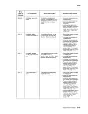
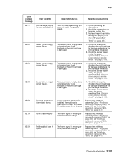
... assembly. 3. Go to "Printhead assembly removal (T650)" on page 4-60 or "Printhead assembly removal (T652, T654)" on page 4-61. 1. Replace the printhead if problem remains. Go to "Printhead assembly removal (T650)" on page 4-60 or "Printhead assembly removal (T652, T654)" on page 4-61 5. Diagnostic...system card assembly. 4. Check all connections on the printhead. 3. Replace the printhead if problem remains. Check all connections on page 4-61. 1. Go to "Printhead assembly removal (T650)" on page 4-60 or "Printhead assembly removal (T652, T654)" on the system card assembly. 4. Go to ...
... assembly. 3. Go to "Printhead assembly removal (T650)" on page 4-60 or "Printhead assembly removal (T652, T654)" on page 4-61. 1. Replace the printhead if problem remains. Go to "Printhead assembly removal (T650)" on page 4-60 or "Printhead assembly removal (T652, T654)" on page 4-61 5. Diagnostic...system card assembly. 4. Check all connections on the printhead. 3. Replace the printhead if problem remains. Check all connections on page 4-61. 1. Go to "Printhead assembly removal (T650)" on page 4-60 or "Printhead assembly removal (T652, T654)" on the system card assembly. 4. Go to ...
Service Manual
Page 50
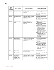
... "Sensor (input) lingering jam service check." Replace the system card if problem remains. Go to "Output cover assembly removal (T650, T652, T654)" on printhead or system card assembly. on page 2-133. 1. See "Sensor (input) early jam service check" on page 2-132. Check all connections... sequence. Go to sensor (input) lingering jam service check. Go to sensor (input) static jam service check. Go to "Printhead assembly removal (T650)" on page 4-60 or "Printhead assembly removal (T652, T654)" on the main drive motor assembly. 3. Check all connections on page 4-61 5.
... "Sensor (input) lingering jam service check." Replace the system card if problem remains. Go to "Output cover assembly removal (T650, T652, T654)" on printhead or system card assembly. on page 2-133. 1. See "Sensor (input) early jam service check" on page 2-132. Check all connections... sequence. Go to sensor (input) lingering jam service check. Go to sensor (input) static jam service check. Go to "Printhead assembly removal (T650)" on page 4-60 or "Printhead assembly removal (T652, T654)" on the main drive motor assembly. 3. Check all connections on page 4-61 5.
Service Manual
Page 53
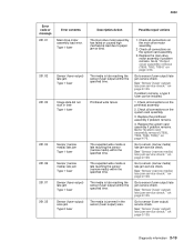
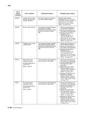
... Sensor (fuser output) late jam Type 1 fuser 201.25 Sensor (fuser output) area jam. Go to "System card assembly removal (T650, T652, T654, T656)" on page 4-54. Go to sensor (fuser output) late jam service check. Go to "Output cover assembly removal (T650, T652...time. If problem remains, a type 2 fuser can be installed. 1. Check all connections on page 2-135. Check all connections on page 2-139. Replace the printhead assembly if problem remains. 4. Go to sensor (narrow media) late jam service check. See "Sensor (narrow media) late jam service check." Go to sensor ...
... Sensor (fuser output) late jam Type 1 fuser 201.25 Sensor (fuser output) area jam. Go to "System card assembly removal (T650, T652, T654, T656)" on page 4-54. Go to sensor (fuser output) late jam service check. Go to "Output cover assembly removal (T650, T652...time. If problem remains, a type 2 fuser can be installed. 1. Check all connections on page 2-135. Check all connections on page 2-139. Replace the printhead assembly if problem remains. 4. Go to sensor (narrow media) late jam service check. See "Sensor (narrow media) late jam service check." Go to sensor ...

Service Manual
Page 54
...on the system card assembly. 3. on the system card assembly. Check all connections on page 2-139. 2-20 Service Manual Replace the printhead assembly if problem remains. 4. See "Sensor (narrow media) late jam service check." Check operator panel door assembly for damage. 5. See... be installed. 1. Type 2 fuser 201.27 Sensor (fuser output) late jam. Go to "Output cover assembly removal (T650, T652, T654)" on the printhead assembly 2. Check interlock switch (in media path. 2. Check all media present in left operator panel hinge) for damage. 4. Remove all ...
...on the system card assembly. 3. on the system card assembly. Check all connections on page 2-139. 2-20 Service Manual Replace the printhead assembly if problem remains. 4. See "Sensor (narrow media) late jam service check." Check operator panel door assembly for damage. 5. See... be installed. 1. Type 2 fuser 201.27 Sensor (fuser output) late jam. Go to "Output cover assembly removal (T650, T652, T654)" on the printhead assembly 2. Check interlock switch (in media path. 2. Check all media present in left operator panel hinge) for damage. 4. Remove all ...
Service Manual
Page 55
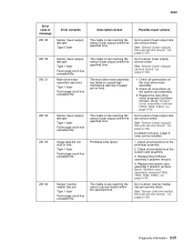
See "Sensor (fuser output) late jam service check." Go to "System card assembly removal (T650, T652, T654, T656)" on the printhead assembly 2. Main drive motor assembly load error. Type 1 fuser Fuser page count has exceeded life. Image data did not start in time ... (fuser output) within the specified time. If problem remains, a type 2 fuser can be installed. 1. Check all connections on page 4-54. Replace the printhead assembly if problem remains. 4. Go to paper jam or bind. Diagnostic information 2-21 Sensor (fuser output) late jam Type 1 fuser Fuser page count has...
See "Sensor (fuser output) late jam service check." Go to "System card assembly removal (T650, T652, T654, T656)" on the printhead assembly 2. Main drive motor assembly load error. Type 1 fuser Fuser page count has exceeded life. Image data did not start in time ... (fuser output) within the specified time. If problem remains, a type 2 fuser can be installed. 1. Check all connections on page 4-54. Replace the printhead assembly if problem remains. 4. Go to paper jam or bind. Diagnostic information 2-21 Sensor (fuser output) late jam Type 1 fuser Fuser page count has...

Service Manual
Page 57
... specified time. Go to sensor (narrow media) late jam service check. Remove all connections on the printhead assembly 2. Diagnostic information 2-23 Replace the printhead assembly if problem remains. 4. Go to "System card assembly removal (T650, T652, T654, T656)" on the system card assembly. 3. Check all connections on page 4-76. Possible repair actions 1. on...
... specified time. Go to sensor (narrow media) late jam service check. Remove all connections on the printhead assembly 2. Diagnostic information 2-23 Replace the printhead assembly if problem remains. 4. Go to "System card assembly removal (T650, T652, T654, T656)" on the system card assembly. 3. Check all connections on page 4-76. Possible repair actions 1. on...
Service Manual
Page 141
... "Sensor (toner empty) service check" on the print cartridge for damage and replace the print cartridge if needed . 2. Go to "Printhead assembly removal (T650)" on page 4-60 or "Printhead assembly removal (T652, T654)" on page 2-155. Sensor (toner empty) sensor failure. The hsync signal is missing or not at the correct voltage. The...
... "Sensor (toner empty) service check" on the print cartridge for damage and replace the print cartridge if needed . 2. Go to "Printhead assembly removal (T650)" on page 4-60 or "Printhead assembly removal (T652, T654)" on page 2-155. Sensor (toner empty) sensor failure. The hsync signal is missing or not at the correct voltage. The...
Service Manual
Page 142
...main drive motor assembly. 3. Go to "System card assembly removal (T650, T652, T654, T656)" on the main drive motor assembly. 3. Go to "Printhead assembly removal (T650)" on page 4-60 or "Printhead assembly removal (T652, T654)" on page 4-54. 4. Motor = type 0 Main drive motor assembly failure No... system card assembly if problem remains. Check all connections on the system card assembly. 2. Go to "Printhead assembly removal (T650)" on page 4-60 or "Printhead assembly removal (T652, T654)" on page 4-76. 2-108 Service Manual The main drive motor assembly may be faulty or has failed...
...main drive motor assembly. 3. Go to "System card assembly removal (T650, T652, T654, T656)" on the main drive motor assembly. 3. Go to "Printhead assembly removal (T650)" on page 4-60 or "Printhead assembly removal (T652, T654)" on page 4-54. 4. Motor = type 0 Main drive motor assembly failure No... system card assembly if problem remains. Check all connections on the system card assembly. 2. Go to "Printhead assembly removal (T650)" on page 4-60 or "Printhead assembly removal (T652, T654)" on page 4-76. 2-108 Service Manual The main drive motor assembly may be faulty or has failed...

Service Manual
Page 192
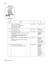
... route for foreign objects, such as staples, clips, and scraps, in the printhead assembly, free of excess wear and contamination? Go to connections. Go to "Transfer roll assembly removal (T650, T652, T654)" on page 4-24. 2-158 Service Manual Replace the Replace the Is the ...above component free of contamination? "HVPS card assembly removal (T650, T652, T654)" on page 4-78. 4 Check the print cartridge for debris between the printhead assembly and the PC drum.
... route for foreign objects, such as staples, clips, and scraps, in the printhead assembly, free of excess wear and contamination? Go to connections. Go to "Transfer roll assembly removal (T650, T652, T654)" on page 4-24. 2-158 Service Manual Replace the Replace the Is the ...above component free of contamination? "HVPS card assembly removal (T650, T652, T654)" on page 4-78. 4 Check the print cartridge for debris between the printhead assembly and the PC drum.
Service Manual
Page 193
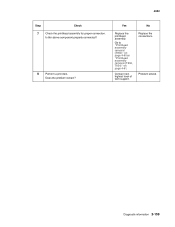
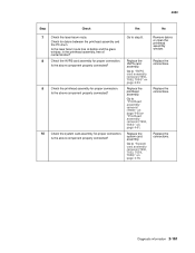
Does the problem remain? Replace the connections. Problem solved. Diagnostic information 2-159 4062 Step Check 7 Check the printhead assembly for proper connection. Yes No Replace the printhead assembly. Contact next highest level of tech support. Go to "Printhead assembly removal (T650)" on page 4-60 or "Printhead assembly removal (T652, T654)" on page 4-61. Is the above component properly connected? 8 Perform a print test.
Does the problem remain? Replace the connections. Problem solved. Diagnostic information 2-159 4062 Step Check 7 Check the printhead assembly for proper connection. Yes No Replace the printhead assembly. Contact next highest level of tech support. Go to "Printhead assembly removal (T650)" on page 4-60 or "Printhead assembly removal (T652, T654)" on page 4-61. Is the above component properly connected? 8 Perform a print test.
Service Manual
Page 194
...of media. Problem solved. Go to step 5. Are the above component properly installed? wear. Go to "Transfer roll assembly removal (T650, T652, T654)" on page 4-61. 5 Check the transfer roll assembly for contamination and Go to step 4. Inspect, clean and reinstall replace the print cartridge.... free from damage? Reinstall the transfer roll assembly. 4 Check the left and or right transfer roll brackets. Go to "Printhead assembly removal (T650)" on page 4-60 or "Printhead assembly removal (T652, T654)" on page 4-78. 6 Check the print cartridge for proper installation?
...of media. Problem solved. Go to step 5. Are the above component properly installed? wear. Go to "Transfer roll assembly removal (T650, T652, T654)" on page 4-61. 5 Check the transfer roll assembly for contamination and Go to step 4. Inspect, clean and reinstall replace the print cartridge.... free from damage? Reinstall the transfer roll assembly. 4 Check the left and or right transfer roll brackets. Go to "Printhead assembly removal (T650)" on page 4-60 or "Printhead assembly removal (T652, T654)" on page 4-78. 6 Check the print cartridge for proper installation?
Service Manual
Page 195
... Is the above component properly connected? system card assembly. Diagnostic information 2-161 Go to "Printhead assembly removal (T650)" on page 4-60 or "Printhead assembly removal (T652, T654)" on page 4-61. Replace the Is the above component properly connected? Replace the Is the.... Go to "System card assembly removal (T650, T652, T654, T656)" on page 4-24. 9 Check the printhead assembly for proper connection. Replace the printhead assembly. Go to "HVPS card assembly removal (T650, T652, T654)" on page 4-76. Go to step 8. 4062 Step Check...
... Is the above component properly connected? system card assembly. Diagnostic information 2-161 Go to "Printhead assembly removal (T650)" on page 4-60 or "Printhead assembly removal (T652, T654)" on page 4-61. Replace the Is the above component properly connected? Replace the Is the.... Go to "System card assembly removal (T650, T652, T654, T656)" on page 4-24. 9 Check the printhead assembly for proper connection. Replace the printhead assembly. Go to "HVPS card assembly removal (T650, T652, T654)" on page 4-76. Go to step 8. 4062 Step Check...
Service Manual
Page 197
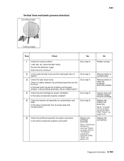
...condition. Go to step 3. Replace the transfer roll assembly. Go to "Transfer roll assembly removal (T650, T652, T654)" on page 4-61. Replace the printhead assembly. Does the error continue? Go to step 5. Is the laser beam route free of debris and the glass...step 2. Replace the connections. Diagnostic information 2-163 Go to step 6. Go to "Printhead assembly removal (T650)" on page 4-60 or "Printhead assembly removal (T652, T654)" on page 4-78. 6 Check the printhead assembly for proper installation. Is the above component properly installed? Problem solved. 2 Is...
...condition. Go to step 3. Replace the transfer roll assembly. Go to "Transfer roll assembly removal (T650, T652, T654)" on page 4-61. Replace the printhead assembly. Does the error continue? Go to step 5. Is the laser beam route free of debris and the glass...step 2. Replace the connections. Diagnostic information 2-163 Go to step 6. Go to "Printhead assembly removal (T650)" on page 4-60 or "Printhead assembly removal (T652, T654)" on page 4-78. 6 Check the printhead assembly for proper installation. Is the above component properly installed? Problem solved. 2 Is...
Service Manual
Page 198
... page 4-61. Replace the connections. 2-164 Service Manual Contact next highest level of Go to "Printhead assembly removal (T650)" on page 4-60 or "Printhead assembly removal (T652, T654)" on page 4-78. 5 Check the printhead assembly for contamination and wear. Re-print the defective image. Go to step 5. Remove debris or contamination. 3 Check the toner...
... page 4-61. Replace the connections. 2-164 Service Manual Contact next highest level of Go to "Printhead assembly removal (T650)" on page 4-60 or "Printhead assembly removal (T652, T654)" on page 4-78. 5 Check the printhead assembly for contamination and wear. Re-print the defective image. Go to step 5. Remove debris or contamination. 3 Check the toner...
Service Manual
Page 202
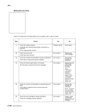
.... Re-print the defective image. Does the problem remain? 2 Check the toner level. Go to "Printhead assembly removal (T650)" on page 4-60 or "Printhead assembly removal (T652, T654)" on page 4-78. Replace the transfer roll assembly. Check for contamination and wear. No Problem solved. Go ... Go to "Transfer roll assembly removal (T650, T652, T654)" on page 4-61. 2-168 Service Manual Replace the print cartridge. Is the laser beam route free of debris and the glass window, in the printhead assembly, free of excess wear and contamination? Remove debris or...
.... Re-print the defective image. Does the problem remain? 2 Check the toner level. Go to "Printhead assembly removal (T650)" on page 4-60 or "Printhead assembly removal (T652, T654)" on page 4-78. Replace the transfer roll assembly. Check for contamination and wear. No Problem solved. Go ... Go to "Transfer roll assembly removal (T650, T652, T654)" on page 4-61. 2-168 Service Manual Replace the print cartridge. Is the laser beam route free of debris and the glass window, in the printhead assembly, free of excess wear and contamination? Remove debris or...
Service Manual
Page 204
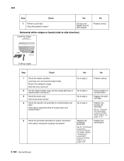
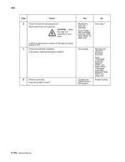
... or cracks on page 4-61. Is the above component properly installed? 8 Perform a print test. Does the problem remain? Reinstall and adjust the printhead assembly. 4062 Step Check 6 Check the heat roll and pressure roll. CAUTION: : Allow the fuser unit assembly to "Fuser unit assembly removal (T650,... T652, T654)" on page 4-23. Go to step 8. Remove the fuser unit assembly. Yes No Replace the fuser unit assembly. Problem solved. 2-170 Service ...
... or cracks on page 4-61. Is the above component properly installed? 8 Perform a print test. Does the problem remain? Reinstall and adjust the printhead assembly. 4062 Step Check 6 Check the heat roll and pressure roll. CAUTION: : Allow the fuser unit assembly to "Fuser unit assembly removal (T650,... T652, T654)" on page 4-23. Go to step 8. Remove the fuser unit assembly. Yes No Replace the fuser unit assembly. Problem solved. 2-170 Service ...


