Service Manual
Page 6
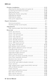
... 3-90 Hole punch adjustment 3-94 Repair information 4-1 Service precautions 4-1 Handling printed circuit boards 4-1 Adjustments 4-3 High-capacity paper feed timing belt adjustment 4-3 Removals 4-4 Cover, top removal 4-4 Cover, front removal 4-5 Cover, front left removal 4-5 Cover, rear removal 4-6 Cover,... side removal 4-7 Cover, right side removal 4-8 Cover, RIP board removal 4-9 Tray, paper exit removal 4-10 Belt up/down clutch removal 4-10 Belt up/down detection sensor removal 4-11 Cassette guide removal 4-12 Connector, duplex unit removal 4-13 Separation fingers removal ...
... 3-90 Hole punch adjustment 3-94 Repair information 4-1 Service precautions 4-1 Handling printed circuit boards 4-1 Adjustments 4-3 High-capacity paper feed timing belt adjustment 4-3 Removals 4-4 Cover, top removal 4-4 Cover, front removal 4-5 Cover, front left removal 4-5 Cover, rear removal 4-6 Cover,... side removal 4-7 Cover, right side removal 4-8 Cover, RIP board removal 4-9 Tray, paper exit removal 4-10 Belt up/down clutch removal 4-10 Belt up/down detection sensor removal 4-11 Cassette guide removal 4-12 Connector, duplex unit removal 4-13 Separation fingers removal ...

Service Manual
Page 8
... Path select gate removal 4-96 Patting roller removal 4-97 Power supply removal 4-99 Registration roller removal 4-100 Registration roller clutch removal 4-101 Stack area discharge brush removal 4-102 Staple unit removal 4-102 Straight paper exit discharge brush removal 4-103 ...Straight paper exit roller removal 4-103 Timing belts 1 and 2 removal 4-105 Tractor belt removal 4-106 Tractor drive motor assembly removal 4-108 Locations 5-1 Covers diagram 5-1 Major parts diagram 5-2 Sensor and switch...
... Path select gate removal 4-96 Patting roller removal 4-97 Power supply removal 4-99 Registration roller removal 4-100 Registration roller clutch removal 4-101 Stack area discharge brush removal 4-102 Staple unit removal 4-102 Straight paper exit discharge brush removal 4-103 ...Straight paper exit roller removal 4-103 Timing belts 1 and 2 removal 4-105 Tractor belt removal 4-106 Tractor drive motor assembly removal 4-108 Locations 5-1 Covers diagram 5-1 Major parts diagram 5-2 Sensor and switch...
Service Manual
Page 73
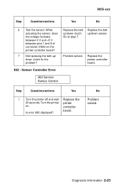
controller Is error 982 displayed? Diagnostic information 2-23 5055-xxx Step Questions/actions Yes No 6 Test the sensor. up/down clutch fix the problem? No Problem solved. between 0 V and +5 V between pins 7 and 8 of connector CN29 on . board. ...Replace the 30 seconds. Turn the printer printer on the printer controller board? 7 Did replacing the belt up /down clutch. the voltage fluctuate Go to step 7. While Replace the belt Replace the belt actuating the sensor, does up / down sensor. Problem solved. Replace the printer controller board. 982 ...
controller Is error 982 displayed? Diagnostic information 2-23 5055-xxx Step Questions/actions Yes No 6 Test the sensor. up/down clutch fix the problem? No Problem solved. between 0 V and +5 V between pins 7 and 8 of connector CN29 on . board. ...Replace the 30 seconds. Turn the printer printer on the printer controller board? 7 Did replacing the belt up /down clutch. the voltage fluctuate Go to step 7. While Replace the belt Replace the belt actuating the sensor, does up / down sensor. Problem solved. Replace the printer controller board. 982 ...

Service Manual
Page 119
...motor turns but the drive gears do not, replace the gears as necessary. Diagnostic information 2-69 Check the feeder solenoid and paper feed clutch for proper operation, and replace as necessary. If this does not correct the problem, replace the expansion feeder control board. FRU 1 ...Feeder drive motor 2 • Gears • Feeder solenoid • Paper feed clutch • Expansion feeder control board Action If the feeder drive motor works, go to the feed roller belts. Replace as necessary. 2 • Duplex stepper motor Be sure the stepper motor turns freely ...
...motor turns but the drive gears do not, replace the gears as necessary. Diagnostic information 2-69 Check the feeder solenoid and paper feed clutch for proper operation, and replace as necessary. If this does not correct the problem, replace the expansion feeder control board. FRU 1 ...Feeder drive motor 2 • Gears • Feeder solenoid • Paper feed clutch • Expansion feeder control board Action If the feeder drive motor works, go to the feed roller belts. Replace as necessary. 2 • Duplex stepper motor Be sure the stepper motor turns freely ...
Service Manual
Page 120
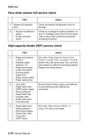
... motor • Paper feed motor • HCPF power supply • Pickup solenoid • Paper feed roller • Transfer roller • Paper feed clutch • Tray drive belt 3 • Paper feed clutch • Pickup solenoid • HCF power supply • Paper feed motor • Tray motor • HCPF board Action Go to the "Maintenance... fluctuation between 0 V and +5 V between pins 2 and 3 of connector CN9 on the printer controller board while actuating the sensor. Be sure that all rollers, gears, and belts are in good working properly.
... motor • Paper feed motor • HCPF power supply • Pickup solenoid • Paper feed roller • Transfer roller • Paper feed clutch • Tray drive belt 3 • Paper feed clutch • Pickup solenoid • HCF power supply • Paper feed motor • Tray motor • HCPF board Action Go to the "Maintenance... fluctuation between 0 V and +5 V between pins 2 and 3 of connector CN9 on the printer controller board while actuating the sensor. Be sure that all rollers, gears, and belts are in good working properly.
Service Manual
Page 122
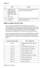
5055-xxx FRU 3 • Registration roller • Paper exit rollers • Registration sensor • Registration clutch • Punch clutch punch unit • Timing belt 4 • Elevator motor • Tray wires Action Run the hole punch test in diagnostic mode to verify the problem has been ...corrected. Marks on paper service check If you remove the transfer belt, do not turn it upside down. Distance between...
5055-xxx FRU 3 • Registration roller • Paper exit rollers • Registration sensor • Registration clutch • Punch clutch punch unit • Timing belt 4 • Elevator motor • Tray wires Action Run the hole punch test in diagnostic mode to verify the problem has been ...corrected. Marks on paper service check If you remove the transfer belt, do not turn it upside down. Distance between...

Service Manual
Page 126
...the sensor. Replace the fuser if necessary. Be sure all guide surfaces in the paper path are free of toner. Check the registration roller clutch for a fluctuation of between 0 V and +5 V between pins 1 and 2 of connector CN11 on the printer controller board while actuating the... at the registration roller or has not reached the fuser (areas C, E, 240, 24x). FRU 1 • Registration roller clutch • Registration roller • Transfer belt unit • Rear paper feed guide 2 • Registration sensor • Printer controller board Action Check these parts for damage.
...the sensor. Replace the fuser if necessary. Be sure all guide surfaces in the paper path are free of toner. Check the registration roller clutch for a fluctuation of between 0 V and +5 V between pins 1 and 2 of connector CN11 on the printer controller board while actuating the... at the registration roller or has not reached the fuser (areas C, E, 240, 24x). FRU 1 • Registration roller clutch • Registration roller • Transfer belt unit • Rear paper feed guide 2 • Registration sensor • Printer controller board Action Check these parts for damage.
Service Manual
Page 129
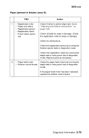
.... Check the registration sensor by running the • Finisher control board staple test or hole punch test in diagnostic mode. Check all belts for wear or damage. Check for obstructions. If the paper feed motor has been replaced, replace the finisher control board. Replace parts ...by running the staple test or hole punch test in diagnostic mode. Paper jammed in diagnostic mode. Go to printer alignment. Check the registration clutch by running the finisher sensor tests in finisher (area G). 5055-xxx FRU Action 1 • Registration roller • Paper exit rollers &#...
.... Check the registration sensor by running the • Finisher control board staple test or hole punch test in diagnostic mode. Check all belts for wear or damage. Check for obstructions. If the paper feed motor has been replaced, replace the finisher control board. Replace parts ...by running the staple test or hole punch test in diagnostic mode. Paper jammed in diagnostic mode. Go to printer alignment. Check the registration clutch by running the finisher sensor tests in finisher (area G). 5055-xxx FRU Action 1 • Registration roller • Paper exit rollers &#...
Service Manual
Page 137
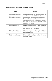
... CN29 is a problem, replace the printer controller board. Replace the belt up /down sensor. Transfer belt up/down service check 5055-xxx FRU 1 Belt up/down sensors Belt up/down actuator 2 Belt up/down clutch 3 Belt up/down lift cams 4 Printer controller board Action Check the transfer belt up /down lift cam shaft if necessary. Replace the sensor...
... CN29 is a problem, replace the printer controller board. Replace the belt up /down sensor. Transfer belt up/down service check 5055-xxx FRU 1 Belt up/down sensors Belt up/down actuator 2 Belt up/down clutch 3 Belt up/down lift cams 4 Printer controller board Action Check the transfer belt up /down lift cam shaft if necessary. Replace the sensor...
Service Manual
Page 193
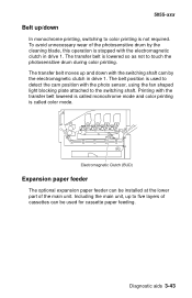
... is not required. Including the main unit, up to color printing is used for cassette paper feeding. The transfer belt is called monochrome mode and color printing is lowered so as not to the switching shaft. Expansion paper feeder The optional expansion paper ...cassettes can be used to detect the cam position with the transfer belt lowered is called color mode. The transfer belt moves up /down with the switching shaft cam by the cleaning blade, this operation is stopped with the electromagnetic clutch in drive 1. Printing with the photo sensor, using the fan shaped...
... is not required. Including the main unit, up to color printing is used for cassette paper feeding. The transfer belt is called monochrome mode and color printing is lowered so as not to the switching shaft. Expansion paper feeder The optional expansion paper ...cassettes can be used to detect the cam position with the transfer belt lowered is called color mode. The transfer belt moves up /down with the switching shaft cam by the cleaning blade, this operation is stopped with the electromagnetic clutch in drive 1. Printing with the photo sensor, using the fan shaped...
Service Manual
Page 256
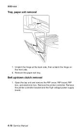
Belt up/down clutch removal 1. Remove the printer controller. 5055-xxx Tray, paper exit removal 1. Open the top unit and remove the RIP cover, RIP board, RIP box, and electronic box. Remove the printer controller bracket and the high voltage power supply board. 4-10 Service Manual Remove the paper exit tray. Unlatch the hinge at the back side, then unlatch the hinge on the front side. 2.
Belt up/down clutch removal 1. Remove the printer controller. 5055-xxx Tray, paper exit removal 1. Open the top unit and remove the RIP cover, RIP board, RIP box, and electronic box. Remove the printer controller bracket and the high voltage power supply board. 4-10 Service Manual Remove the paper exit tray. Unlatch the hinge at the back side, then unlatch the hinge on the front side. 2.
Service Manual
Page 257
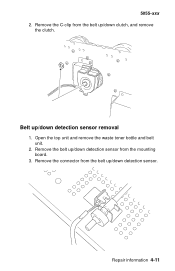
Belt up /down clutch, and remove the clutch. Remove the C-clip from the belt up /down detection sensor from the mounting board. 3. Open the top unit and remove the waste toner bottle and belt unit. 2. Remove the connector from the belt up /down detection sensor removal 1. Repair information 4-11 5055-xxx 2. Remove the belt up /down detection sensor.
Belt up /down clutch, and remove the clutch. Remove the C-clip from the belt up /down detection sensor from the mounting board. 3. Open the top unit and remove the waste toner bottle and belt unit. 2. Remove the connector from the belt up /down detection sensor removal 1. Repair information 4-11 5055-xxx 2. Remove the belt up /down detection sensor.
Service Manual
Page 275
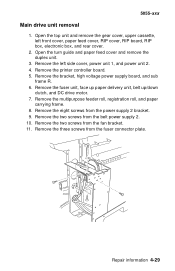
... cover, paper feed cover, RIP cover, RIP board, RIP box, electronic box, and rear cover. 2. Remove the fuser unit, face up paper delivery unit, belt up/down clutch, and DC drive motor. 7. Remove the multipurpose feeder roll, registration roll, and paper carrying frame. 8. Remove the two screws from the fuser connector plate... screws from the power supply 2 bracket. 9. Open the turn guide and paper feed cover and remove the duplex unit. 3. Remove the eight screws from the belt power supply 2. 10.
... cover, paper feed cover, RIP cover, RIP board, RIP box, electronic box, and rear cover. 2. Remove the fuser unit, face up paper delivery unit, belt up/down clutch, and DC drive motor. 7. Remove the multipurpose feeder roll, registration roll, and paper carrying frame. 8. Remove the two screws from the fuser connector plate... screws from the power supply 2 bracket. 9. Open the turn guide and paper feed cover and remove the duplex unit. 3. Remove the eight screws from the belt power supply 2. 10.

Service Manual
Page 278
Remove the left side cover, the solenoid cover, and the rear cover. 2. Remove the screw from the belt up/down clutch box and remove the belt up/down clutch. 19. Main unit fan removal 1. 5055-xxx 18. Remove the three screws from the drum gear sensor and remove the sensor. Remove the two screws from the main unit fan bracket. 3. Remove the fan. 4-32 Service Manual
Remove the left side cover, the solenoid cover, and the rear cover. 2. Remove the screw from the belt up/down clutch box and remove the belt up/down clutch. 19. Main unit fan removal 1. 5055-xxx 18. Remove the three screws from the drum gear sensor and remove the sensor. Remove the two screws from the main unit fan bracket. 3. Remove the fan. 4-32 Service Manual
Service Manual
Page 381
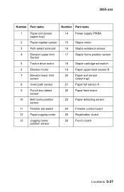
... sensor 3 Path select solenoid 4 Elevator upper limit Sensor 5 Tractor drive motor 6 Elevator motor 7 Elevator lower limit sensor 8 Invert path sensor 9 Punch box detect sensor 10 Belt home position sensor 11 Finisher set switch 12 Paper jogging motor 13 Jogging home position sensor 14 Power supply PWBA 15 Staple motor 16 Staple... sensor B 20 Paper exit sensor (lower tray) 21 Paper full sensor A 22 Paper feed motor 23 Paper detecting sensor 24 Finisher control board 25 Registration clutch 26 Punch clutch Locations 5-27
... sensor 3 Path select solenoid 4 Elevator upper limit Sensor 5 Tractor drive motor 6 Elevator motor 7 Elevator lower limit sensor 8 Invert path sensor 9 Punch box detect sensor 10 Belt home position sensor 11 Finisher set switch 12 Paper jogging motor 13 Jogging home position sensor 14 Power supply PWBA 15 Staple motor 16 Staple... sensor B 20 Paper exit sensor (lower tray) 21 Paper full sensor A 22 Paper feed motor 23 Paper detecting sensor 24 Finisher control board 25 Registration clutch 26 Punch clutch Locations 5-27
Service Manual
Page 401
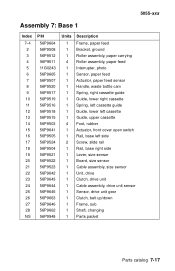
... open switch Rail, base left side Screw, slide rail Rail, base right side Lever, size sensor Board, size sensor Cable assembly, size sensor Unit, drive Clutch, drive unit Cable assembly, drive unit sensor Sensor, drive unit gear Clutch, belt up/down Frame, sub Shaft, changing Parts packet Parts catalog 7-17
... open switch Rail, base left side Screw, slide rail Rail, base right side Lever, size sensor Board, size sensor Cable assembly, size sensor Unit, drive Clutch, drive unit Cable assembly, drive unit sensor Sensor, drive unit gear Clutch, belt up/down Frame, sub Shaft, changing Parts packet Parts catalog 7-17
Service Manual
Page 443
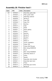
..., guide holder Assembly, solenoid Spring, H Gear, Z20 Gear, Z19 Bushing Gate Roller Roller, patting Roller, I Bushing Spring, A Spring, F Roller, F Roller, G Clutch, registration Pulley, T56 Pulley, Z24/T42 gear Belt, timing 60S2M184 Knob Belt, timing 60S2M334 Assembly, tension D Pulley Spacer Assembly, motor bracket Assembly, feed motor Pulley Assembly, punch drive Spring, B 5055-xxx Parts...
..., guide holder Assembly, solenoid Spring, H Gear, Z20 Gear, Z19 Bushing Gate Roller Roller, patting Roller, I Bushing Spring, A Spring, F Roller, F Roller, G Clutch, registration Pulley, T56 Pulley, Z24/T42 gear Belt, timing 60S2M184 Knob Belt, timing 60S2M334 Assembly, tension D Pulley Spacer Assembly, motor bracket Assembly, feed motor Pulley Assembly, punch drive Spring, B 5055-xxx Parts...
Service Manual
Page 468
...96 power supply 4-99 registration roller 4-100 registration roller clutch 4-101 stack area discharge brush 4-102 staple unit 4-102 straight paper exit discharge brush 4-103 straight paper exit roller 4-103 timing belts 1 and 2 4-105 tractor belt 4-106 tractor drive motor assembly 4-108 stand 3-75...information 1-1 H hardware tests 3-12 high-capacity feeder call roller removal 4-82 covers removal 4-81 diagram 5-18 high-capacity paper feed timing belt adjustment 4-3 paper end sensor removal 4-84 paper feed configuration 5-18 paper feed roller removal 4-82 paper level sensor removal 4-87 paper size ...
...96 power supply 4-99 registration roller 4-100 registration roller clutch 4-101 stack area discharge brush 4-102 staple unit 4-102 straight paper exit discharge brush 4-103 straight paper exit roller 4-103 timing belts 1 and 2 4-105 tractor belt 4-106 tractor drive motor assembly 4-108 stand 3-75...information 1-1 H hardware tests 3-12 high-capacity feeder call roller removal 4-82 covers removal 4-81 diagram 5-18 high-capacity paper feed timing belt adjustment 4-3 paper end sensor removal 4-84 paper feed configuration 5-18 paper feed roller removal 4-82 paper level sensor removal 4-87 paper size ...
Service Manual
Page 470
... printhead LED printhead removal 4-24 parts catalog 7-15 printhead controller board 7-13 printhead controller board removal 4-44 printing menu settings 3-4 R relocation kit 7-73 removals belt up/down clutch 4-10 belt up/down detection sensor 4-11 cassette guide 4-12 connector, duplex unit 4-13 covers front 4-5 front left 4-5 left side 4-7 operator panel 4-34 rear 4-6 right... 4-75 feed roller and solenoid 4-78 paper carrying motor 4-80 pressure roller and solenoid 4-77 side fence motor assembly 4-79 side fence removal 4-79 timing belt 4-76 duplex unit connector 4-13 I-4 Service Manual
... printhead LED printhead removal 4-24 parts catalog 7-15 printhead controller board 7-13 printhead controller board removal 4-44 printing menu settings 3-4 R relocation kit 7-73 removals belt up/down clutch 4-10 belt up/down detection sensor 4-11 cassette guide 4-12 connector, duplex unit 4-13 covers front 4-5 front left 4-5 left side 4-7 operator panel 4-34 rear 4-6 right... 4-75 feed roller and solenoid 4-78 paper carrying motor 4-80 pressure roller and solenoid 4-77 side fence motor assembly 4-79 side fence removal 4-79 timing belt 4-76 duplex unit connector 4-13 I-4 Service Manual
Service Manual
Page 471
...96 power supply 4-99 registration roller 4-100 registration roller clutch 4-101 stack area discharge brush 4-102 staple unit 4-102 straight paper exit discharge brush 4-103 straight paper exit roller 4-103 timing belts 1 and 2 4-105 tractor belt removal 4-106 tractor drive motor assembly 4-108 front cover...board assembly 4-39 power supply 1 4-40 power supply 2 4-41 power switch 4-42 printer controller 4-43 printhead controller board 4-44 registration clutch 4-47 registration frame 4-47 registration sensor 4-48 right slide rail 4-49 RIP box 4-49 sensor board 4-50 sensor cleaner 4-14 separation ...
...96 power supply 4-99 registration roller 4-100 registration roller clutch 4-101 stack area discharge brush 4-102 staple unit 4-102 straight paper exit discharge brush 4-103 straight paper exit roller 4-103 timing belts 1 and 2 4-105 tractor belt removal 4-106 tractor drive motor assembly 4-108 front cover...board assembly 4-39 power supply 1 4-40 power supply 2 4-41 power switch 4-42 printer controller 4-43 printhead controller board 4-44 registration clutch 4-47 registration frame 4-47 registration sensor 4-48 right slide rail 4-49 RIP box 4-49 sensor board 4-50 sensor cleaner 4-14 separation ...


