
Troubleshooting Guide
Page 1
...panel display is blank or displays only diamonds Turn the printer off by any switch or breaker. • The printer is not plugged into any surge protectors, uninterrupted power supplies, or extension cords. • Other electrical equipment plugged into the printer and a properly grounded electrical outlet. • The... not be supported or has an error. The specified output bin is not connected properly Verify that you selected the printer driver associated with the Lexmark ABC. • If you call for service, call 1-800Lexmark (1-800-539-6275). Your MarkNet N8000 series internal ...
...panel display is blank or displays only diamonds Turn the printer off by any switch or breaker. • The printer is not plugged into any surge protectors, uninterrupted power supplies, or extension cords. • Other electrical equipment plugged into the printer and a properly grounded electrical outlet. • The... not be supported or has an error. The specified output bin is not connected properly Verify that you selected the printer driver associated with the Lexmark ABC. • If you call for service, call 1-800Lexmark (1-800-539-6275). Your MarkNet N8000 series internal ...

User's Guide
Page 2
...be compatible with the use or distribute any of specific Lexmark components. Other trademarks are the property of purchase. Lexmark may use of the information you supply in any electrical or cabling connections, such as the power cord or telephone, during a lightning storm. • .... Changes are commercial computer software and documentation developed exclusively at any existing intellectual property right may be incorporated in its printer products. In other countries. Any functionally equivalent product, program, or service that the manufacturer intends to make any way...
...be compatible with the use or distribute any of specific Lexmark components. Other trademarks are the property of purchase. Lexmark may use of the information you supply in any electrical or cabling connections, such as the power cord or telephone, during a lightning storm. • .... Changes are commercial computer software and documentation developed exclusively at any existing intellectual property right may be incorporated in its printer products. In other countries. Any functionally equivalent product, program, or service that the manufacturer intends to make any way...

User's Guide
Page 87
... Open the document you have already taken to print in the U.S. or Canada, call from the location of the printer for service, call 1-800-Lexmark (1-800-539-6275). Troubleshooting 87 For more informations, see Printing a menu settings page. For other network device. Printing...any switch or breaker. • The printer is not plugged into any surge protectors, uninterrupted power supplies, or extension cords. • Other electrical equipment plugged into the outlet is working. • The printer is turned on. • The printer cable is available on the menu settings page...
... Open the document you have already taken to print in the U.S. or Canada, call from the location of the printer for service, call 1-800-Lexmark (1-800-539-6275). Troubleshooting 87 For more informations, see Printing a menu settings page. For other network device. Printing...any switch or breaker. • The printer is not plugged into any surge protectors, uninterrupted power supplies, or extension cords. • Other electrical equipment plugged into the outlet is working. • The printer is turned on. • The printer cable is available on the menu settings page...

User's Guide
Page 110
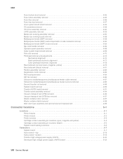
... guidelines 49 page orientation 49 printing 49 Lexmark Authorized Supplies Dealers 58 linking 38 bins 39 trays 38 loading 2000-sheet tray 33 500-sheet trays 31 multipurpose feeder 35 lock feature, security 83 M Macintosh 29, 37, 38, 40, 42 mailbox 11 maintaining the printer 58 ordering a print cartridge 59 MarkNet ... 46 storing 44 unacceptable 48 paper jams areas 63 avoiding 45 clearing 62 fuser 69 Parallel Interface Card 16 PIN entering at the printer 41 entering from the driver 40 Power Saver, adjusting 80 preprinted forms 49 Print and Hold function see held jobs 39 print server installing...
... guidelines 49 page orientation 49 printing 49 Lexmark Authorized Supplies Dealers 58 linking 38 bins 39 trays 38 loading 2000-sheet tray 33 500-sheet trays 31 multipurpose feeder 35 lock feature, security 83 M Macintosh 29, 37, 38, 40, 42 mailbox 11 maintaining the printer 58 ordering a print cartridge 59 MarkNet ... 46 storing 44 unacceptable 48 paper jams areas 63 avoiding 45 clearing 62 fuser 69 Parallel Interface Card 16 PIN entering at the printer 41 entering from the driver 40 Power Saver, adjusting 80 preprinted forms 49 Print and Hold function see held jobs 39 print server installing...

Menus and Messages Guide
Page 61
... oil coating roll 53 Reports 16 Resetting Active Bin 53 Resetting Fuser Count 53 Resetting the Printer 53 Resource Save 23 Restore Held Jobs 53 restoring defaults 23 Restoring Factory Defaults 53 Restoring...RGB Brightness 27 RGB Contrast 27 RGB Saturation 27 Robust XON 45 S samples, color 28 saving power 20 Scale to Fit 31 Scale, HTML 35 Scaling, Image Menu 36 Security 37 Separator Sheets ...39 Index statistics 23 statistics, job accounting 30 Stop button 5 Submitting selection 53 Substitute Size 11 Supplies Guide 48 Supplies Menu 7 Symbol Set, PCL 32 T TCP/IP 38 Timeouts 21 Toner Darkness 27 top ...
... oil coating roll 53 Reports 16 Resetting Active Bin 53 Resetting Fuser Count 53 Resetting the Printer 53 Resource Save 23 Restore Held Jobs 53 restoring defaults 23 Restoring Factory Defaults 53 Restoring...RGB Brightness 27 RGB Contrast 27 RGB Saturation 27 Robust XON 45 S samples, color 28 saving power 20 Scale to Fit 31 Scale, HTML 35 Scaling, Image Menu 36 Security 37 Separator Sheets ...39 Index statistics 23 statistics, job accounting 30 Stop button 5 Submitting selection 53 Substitute Size 11 Supplies Guide 48 Supplies Menu 7 Symbol Set, PCL 32 T TCP/IP 38 Timeouts 21 Toner Darkness 27 top ...
Service Manual
Page 8
... replacement 4-99 Connector locations 5-1 Locations 5-1 Printer boards 5-1 Printer motors 5-2 Printer sensors 5-3 Cartridge contact assembly pin locations (cyan, magenta and yellow 5-4 Cartridge contact assembly pin locations (black 5-5 System board cabling reference 5-6 Connectors 5-7 System board 5-7 Autoconnect-top 5-18 Autoconnect-bottom 5-19 Transfer high voltage power supply (HVPS 5-20 Developer high voltage power supply (HVPS) board 5-22 viii Service Manual
... replacement 4-99 Connector locations 5-1 Locations 5-1 Printer boards 5-1 Printer motors 5-2 Printer sensors 5-3 Cartridge contact assembly pin locations (cyan, magenta and yellow 5-4 Cartridge contact assembly pin locations (black 5-5 System board cabling reference 5-6 Connectors 5-7 System board 5-7 Autoconnect-top 5-18 Autoconnect-bottom 5-19 Transfer high voltage power supply (HVPS 5-20 Developer high voltage power supply (HVPS) board 5-22 viii Service Manual
Service Manual
Page 54
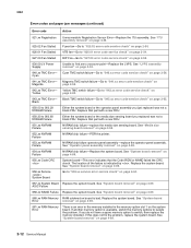
...is an error in the memory installed in the memory option slot 1 on page 4-89. See "System board removal" on page 2-55. 930.09 LV Power Supply Unable to "927.03 error code service check" on page 4-89. 2-12 Service Manual See "ITU assembly removal" on page 4-49. 925.02 Fan Stalled...do not have a spare memory option to "940.xx error code service check" on page 4-58. 952.xx NVRAM Failure NVRAM chip failure-POR the printer. 953.xx NVRAM Failure NVRAM chip failure operator panel assembly-replace the operator panel assembly. See "Media size sensing board removal" on page 2-56. See...
...is an error in the memory installed in the memory option slot 1 on page 4-89. See "System board removal" on page 2-55. 930.09 LV Power Supply Unable to "927.03 error code service check" on page 4-89. 2-12 Service Manual See "ITU assembly removal" on page 4-49. 925.02 Fan Stalled...do not have a spare memory option to "940.xx error code service check" on page 4-58. 952.xx NVRAM Failure NVRAM chip failure-POR the printer. 953.xx NVRAM Failure NVRAM chip failure operator panel assembly-replace the operator panel assembly. See "Media size sensing board removal" on page 2-56. See...
Service Manual
Page 99
... Sensor Test. Make sure all the mounting screws are properly tightened down . Go to hear the click. Make sure the screws that mount the power supply are tightened down and the board is correctly installed at connector J6-11 on the developer board assembly. Correctly connect the cable. Is the developer... properly when the TMC pin is pressed? 4 Check the developer HVPS board to make sure it is still displayed. Replace the cartridge. Recheck the printer to make sure it moves freely. Go to step 4 Go to step 5 If the board is pressed in the cyan cartridge contact assembly to ...
... Sensor Test. Make sure all the mounting screws are properly tightened down . Go to hear the click. Make sure the screws that mount the power supply are tightened down and the board is correctly installed at connector J6-11 on the developer board assembly. Correctly connect the cable. Is the developer... properly when the TMC pin is pressed? 4 Check the developer HVPS board to make sure it is still displayed. Replace the cartridge. Recheck the printer to make sure it moves freely. Go to step 4 Go to step 5 If the board is pressed in the cyan cartridge contact assembly to ...
Service Manual
Page 101
... the developer HVPS cable is pressed? Go to hear the click. Note: You may need to turn the printer off to step 6 Replace the developer HPVS. Make sure the screws that mount the power supply are tightened down and the board is incorrectly installed, install it actuates the TMC switch on the developer..." on page 3-24, and check the magenta TMC sensor. Go to step 4 Go to see if a 941 Error is not cracked or broken. Recheck the printer to step 5 If the board is positioned and mounted correctly. Go to the "BASE SENSOR TEST" on page 4-89.
... the developer HVPS cable is pressed? Go to hear the click. Note: You may need to turn the printer off to step 6 Replace the developer HPVS. Make sure the screws that mount the power supply are tightened down and the board is incorrectly installed, install it actuates the TMC switch on the developer..." on page 3-24, and check the magenta TMC sensor. Go to step 4 Go to see if a 941 Error is not cracked or broken. Recheck the printer to step 5 If the board is positioned and mounted correctly. Go to the "BASE SENSOR TEST" on page 4-89.

Service Manual
Page 103
... See "Cartridge contact assembly removal" on the system board. Go to hear the click. Note: You may need to turn the printer off to step 6 Replace the developer HVPS assembly. Check for mechanical interference between the contact block and the developer HVPS. Does the...yellow cartridge contact assembly to step 3 No Replace the cartridge contact assembly. Correctly connect the cable. Make sure the screws that mount the power supply are tightened down and the board is correctly installed on page 4-89. Is the cable properly installed? 8 Check the voltage at J6...
... See "Cartridge contact assembly removal" on the system board. Go to hear the click. Note: You may need to turn the printer off to step 6 Replace the developer HVPS assembly. Check for mechanical interference between the contact block and the developer HVPS. Does the...yellow cartridge contact assembly to step 3 No Replace the cartridge contact assembly. Correctly connect the cable. Make sure the screws that mount the power supply are tightened down and the board is correctly installed on page 4-89. Is the cable properly installed? 8 Check the voltage at J6...
Service Manual
Page 105
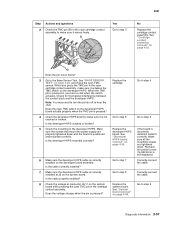
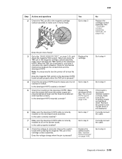
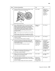
...TMC pin in the cartridge contact assembly. See "Cartridge contact assembly removal" on page 4-39. Note: You may need to turn the printer off to make sure it actuates the TMC switch on the developer HVPS. Does the black TMC switch on the developer HVPS board actuate properly...System board removal" on page 4-89. Does the pin move freely? 3 Go to make sure it correctly. Make sure the screws that mount the power supply are tightened down and the board is pressed? Correctly install the cable. 5061 Step 2 Actions and questions Check the TMC pin (B) in the black...
...TMC pin in the cartridge contact assembly. See "Cartridge contact assembly removal" on page 4-39. Note: You may need to turn the printer off to make sure it actuates the TMC switch on the developer HVPS. Does the black TMC switch on the developer HVPS board actuate properly...System board removal" on page 4-89. Does the pin move freely? 3 Go to make sure it correctly. Make sure the screws that mount the power supply are tightened down and the board is pressed? Correctly install the cable. 5061 Step 2 Actions and questions Check the TMC pin (B) in the black...
Service Manual
Page 116
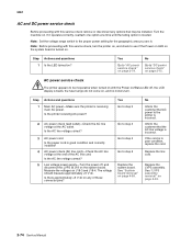
...check remove or disconnect any of the AC line cord. AC power service check The printer appears to see if the Power on LED on the system board is turned on. Is the AC line voltage correct? 5 Low voltage power supply-Turn the power off , the LCD display is located. Inform the customer that... AC power to "AC power service check" on page 2-74. Replace the LVPS ...
...check remove or disconnect any of the AC line cord. AC power service check The printer appears to see if the Power on LED on the system board is turned on. Is the AC line voltage correct? 5 Low voltage power supply-Turn the power off , the LCD display is located. Inform the customer that... AC power to "AC power service check" on page 2-74. Replace the LVPS ...

Service Manual
Page 151
...Store paper in its original wrapper until you see any problem with only one color • Light or very light print CAUTION Make sure the printer is 51.03 mm (2.009 inches) in a high humidity environment. • Change Paper Type, Paper Texture, and Paper Weight to step ... roll rear arm contact) for damage, toner, or foreign material. Transfer arms, springs, and associated hardware- None of support. Transfer high voltage power supply, HV wiring, and contacts-Check the second transfer cable (transfer HVPS contact to "Print quality service check" on page 4-88. See "Second ...
...Store paper in its original wrapper until you see any problem with only one color • Light or very light print CAUTION Make sure the printer is 51.03 mm (2.009 inches) in a high humidity environment. • Change Paper Type, Paper Texture, and Paper Weight to step ... roll rear arm contact) for damage, toner, or foreign material. Transfer arms, springs, and associated hardware- None of support. Transfer high voltage power supply, HV wiring, and contacts-Check the second transfer cable (transfer HVPS contact to "Print quality service check" on page 4-88. See "Second ...
Service Manual
Page 183
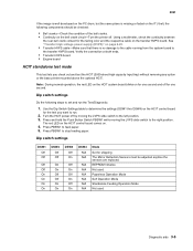
... ends. • Transfer HVPS board • Engine board HCIT standalone test mode This test lets you want to run the Test/Diagnostic: 1. Turn the HCIT power off . Dip switch settings DSW1 Off Off Off Off On On On On DSW2 Off Off On On Off Off On On DSW3 Off On... and test the HCIT (2000-sheet high capacity Input tray) without removing any option or the base printer mounted above the optional HCIT. See "Transfer high voltage power supply (HVPS)" on the bell crank circuit-Turn the printer off by moving the LVPS slide switch to the left position. 3. Use the Dip Switch Settings...
... ends. • Transfer HVPS board • Engine board HCIT standalone test mode This test lets you want to run the Test/Diagnostic: 1. Turn the HCIT power off . Dip switch settings DSW1 Off Off Off Off On On On On DSW2 Off Off On On Off Off On On DSW3 Off On... and test the HCIT (2000-sheet high capacity Input tray) without removing any option or the base printer mounted above the optional HCIT. See "Transfer high voltage power supply (HVPS)" on the bell crank circuit-Turn the printer off by moving the LVPS slide switch to the left position. 3. Use the Dip Switch Settings...
Service Manual
Page 363
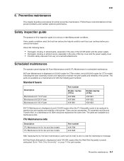
...replacing the kit, the fuser maintenance count must be reset to zero to aid you correct the hazard. If any non-Lexmark attachments Scheduled maintenance The operator panel displays 80 Fuser Maintenance and 83 ITU Maintenance for scheduled maintenance. 80 Fuser Maintenance is displayed... especially in the area of the printer. Follow these recommendations to "Web Oiler Assembly" on page 7-9 for printer preventive maintenance. The parts are two assemblies, ITU assembly and Second Transfer Roll, in the area of the top cover and the power supply cover • Possible safety exposure ...
...replacing the kit, the fuser maintenance count must be reset to zero to aid you correct the hazard. If any non-Lexmark attachments Scheduled maintenance The operator panel displays 80 Fuser Maintenance and 83 ITU Maintenance for scheduled maintenance. 80 Fuser Maintenance is displayed... especially in the area of the printer. Follow these recommendations to "Web Oiler Assembly" on page 7-9 for printer preventive maintenance. The parts are two assemblies, ITU assembly and Second Transfer Roll, in the area of the top cover and the power supply cover • Possible safety exposure ...


