
Hardware Maintenance Manual
Page 4
... emission notices 86 Trademarks 86 ii Hardware Maintenance Manual 1060 PCI Express Mini Card for wireless WAN or mSATA solid-state drive 61 1070 Keyboard 64 1080 Keyboard bezel assembly 67 1090 Microphone 69 1100 Speaker assembly 70 1110 I/O board 71 1120 CRT board assembly (with cable) . . . . . 72 1130 System board assembly...
... emission notices 86 Trademarks 86 ii Hardware Maintenance Manual 1060 PCI Express Mini Card for wireless WAN or mSATA solid-state drive 61 1070 Keyboard 64 1080 Keyboard bezel assembly 67 1090 Microphone 69 1100 Speaker assembly 70 1110 I/O board 71 1120 CRT board assembly (with cable) . . . . . 72 1130 System board assembly...
Hardware Maintenance Manual
Page 30
...the spindle of a hard disk drive becomes noisy, it might be downloaded from the Lenovo Support Web site. • The two programs are intended to computers installed with the ThinkPad notebook computer. For additional information about this program, see the help information system. Checkout...• Forgotten computer password (making the computer unusable) • Sticky keys caused by spilling a liquid onto the keyboard • Use of errors and invalid system responses. 1. Verify the symptoms. Try to http://www.lenovo.com/diags, and follow the instructions on the screen.
...the spindle of a hard disk drive becomes noisy, it might be downloaded from the Lenovo Support Web site. • The two programs are intended to computers installed with the ThinkPad notebook computer. For additional information about this program, see the help information system. Checkout...• Forgotten computer password (making the computer unusable) • Sticky keys caused by spilling a liquid onto the keyboard • Use of errors and invalid system responses. 1. Verify the symptoms. Try to http://www.lenovo.com/diags, and follow the instructions on the screen.
Hardware Maintenance Manual
Page 38
..." has been set on the timer, and the user does not do any input immediately after it enters sleep mode. Press F10 to enter the ThinkPad Setup program. 3. Screen blank mode If the time set on the "Turn off monitor" timer in screen blank mode: • The LCD is powered ... a serial device or a PC Card device. • The time set on the resume timer elapses. Note: The computer does not accept any operation with the keyboard, the TrackPoint®, the hard disk drive, or the parallel connector within that time. • If the battery indicator blinks orange, indicating that the battery...
..." has been set on the timer, and the user does not do any input immediately after it enters sleep mode. Press F10 to enter the ThinkPad Setup program. 3. Screen blank mode If the time set on the "Turn off monitor" timer in screen blank mode: • The LCD is powered ... a serial device or a PC Card device. • The time set on the resume timer elapses. Note: The computer does not accept any operation with the keyboard, the TrackPoint®, the hard disk drive, or the parallel connector within that time. • If the battery indicator blinks orange, indicating that the battery...

Hardware Maintenance Manual
Page 39
...is restored from hibernation mode and resumes operation. Do not replace a nondefective FRU. Note: For a device not supported by diagnostic codes in the ThinkPad notebook computers, see the manual for each error detected in the boot record on , the computer returns from the hard disk drive. When the...." In the displays, n can also help you determine, during regular servicing, what FRUs are likely to need to be any operation with the keyboard, the TrackPoint, the hard disk drive, or the parallel connector within that causes the system to go to "Intermittent problems" on page 36 The...
...is restored from hibernation mode and resumes operation. Do not replace a nondefective FRU. Note: For a device not supported by diagnostic codes in the ThinkPad notebook computers, see the manual for each error detected in the boot record on , the computer returns from the hard disk drive. When the...." In the displays, n can also help you determine, during regular servicing, what FRUs are likely to need to be any operation with the keyboard, the TrackPoint, the hard disk drive, or the parallel connector within that causes the system to go to "Intermittent problems" on page 36 The...

Hardware Maintenance Manual
Page 47
...+F6 to open the Communications settings window. The computer display becomes brighter. Fn key combinations The following device drivers must have the ThinkPad Power Management driver installed on the list. Fn+F5 Notes: • To use Fn+F5 to use the Fn+F4 key combination...the camera and audio settings, and launch the Communications Utility program. Has the same function as the Pause key on a conventional keyboard. © Copyright Lenovo 2012 41 Table 7. The computer display becomes dimmer. You can use the combination to switch between the computer display and an ...
...+F6 to open the Communications settings window. The computer display becomes brighter. Fn key combinations The following device drivers must have the ThinkPad Power Management driver installed on the list. Fn+F5 Notes: • To use Fn+F5 to use the Fn+F4 key combination...the camera and audio settings, and launch the Communications Utility program. Has the same function as the Pause key on a conventional keyboard. © Copyright Lenovo 2012 41 Table 7. The computer display becomes dimmer. You can use the combination to switch between the computer display and an ...

Hardware Maintenance Manual
Page 51
...is visible. Click User Guides & Manuals and then follow the on-screen instructions to you might include the memory module, wireless card, keyboard, and palm rest with a replacement part you can find the manual for your receipt of CRUs include the ac power adapter, power ...are shipped with the replacement CRU; Installation of CRUs: - Other self-service CRUs depending on installing the CRU, Lenovo will be found at any time upon request. ThinkPad computers contain the following types of self-service CRUs is your product and are designated as optional-service CRUs.
...is visible. Click User Guides & Manuals and then follow the on-screen instructions to you might include the memory module, wireless card, keyboard, and palm rest with a replacement part you can find the manual for your receipt of CRUs include the ac power adapter, power ...are shipped with the replacement CRU; Installation of CRUs: - Other self-service CRUs depending on installing the CRU, Lenovo will be found at any time upon request. ThinkPad computers contain the following types of self-service CRUs is your product and are designated as optional-service CRUs.

Hardware Maintenance Manual
Page 52
Major FRUs and CRUs 1 19 18 17 16 15 14 13 12 11 10 Table 8. Major FRUs and CRUs No. FRU description 1 LCD unit (See "LCD FRUs and CRUs" on page 48.) 2 Keyboard bezel assembly 3 Backup battery 46 Hardware Maintenance Manual 2 3 4 5 6 7 8 9 Self-service CRU No No Yes Optional-service CRU No No No
Major FRUs and CRUs 1 19 18 17 16 15 14 13 12 11 10 Table 8. Major FRUs and CRUs No. FRU description 1 LCD unit (See "LCD FRUs and CRUs" on page 48.) 2 Keyboard bezel assembly 3 Backup battery 46 Hardware Maintenance Manual 2 3 4 5 6 7 8 9 Self-service CRU No No Yes Optional-service CRU No No No

Hardware Maintenance Manual
Page 53
... 11 mSATA solid-state drive 12 Memory module 13 Speaker assembly 14 CRT board assembly 15 System board 16 Thermal fan assembly 17 Microphone 18 Keyboard 19 TrackPoint cap Self-service CRU No Yes No No Yes Yes Yes Yes No Yes No No No No No Yes Yes Optional-service...
... 11 mSATA solid-state drive 12 Memory module 13 Speaker assembly 14 CRT board assembly 15 System board 16 Thermal fan assembly 17 Microphone 18 Keyboard 19 TrackPoint cap Self-service CRU No Yes No No Yes Yes Yes Yes No Yes No No No No No Yes Yes Optional-service...

Hardware Maintenance Manual
Page 70
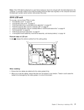
• After installation of a new drive, go to http://www.lenovo.com/support for instructions on configuring the drive. 1 Step 1 Screw (quantity) M2 × 3 mm, wafer-head, nylon-coated (1) 2 Color Black Torque 0.181 Nm (1.85 kgfcm) 1070 Keyboard For access, remove these FRUs in order: • "1010 Battery pack" on page 56 • "1020 Bottom slot cover" on page 57 64 Hardware Maintenance Manual
• After installation of a new drive, go to http://www.lenovo.com/support for instructions on configuring the drive. 1 Step 1 Screw (quantity) M2 × 3 mm, wafer-head, nylon-coated (1) 2 Color Black Torque 0.181 Nm (1.85 kgfcm) 1070 Keyboard For access, remove these FRUs in order: • "1010 Battery pack" on page 56 • "1020 Bottom slot cover" on page 57 64 Hardware Maintenance Manual

Hardware Maintenance Manual
Page 71
Removing or replacing a FRU 65 Removal steps of keyboard 1 1 When installing: Ensure that the screws have been fastened to secure the keyboard. Step 1 Screw (quantity) M2 × 8 mm, wafer-head, nylon-coated (2) Color Black Torque 0.181 Nm (1.85 kgfcm) 2 2 Chapter 9.
Removing or replacing a FRU 65 Removal steps of keyboard 1 1 When installing: Ensure that the screws have been fastened to secure the keyboard. Step 1 Screw (quantity) M2 × 8 mm, wafer-head, nylon-coated (2) Color Black Torque 0.181 Nm (1.85 kgfcm) 2 2 Chapter 9.

Hardware Maintenance Manual
Page 72
Attach the keyboard and ensure that the hooks on the front edge of keyboard To install the keyboard, do the following: 1. Attach the connectors. 2. 4 4 4 4 3 8 6 9 7 5 Installation steps of the keyboard are under the frame. 66 Hardware Maintenance Manual
Attach the keyboard and ensure that the hooks on the front edge of keyboard To install the keyboard, do the following: 1. Attach the connectors. 2. 4 4 4 4 3 8 6 9 7 5 Installation steps of the keyboard are under the frame. 66 Hardware Maintenance Manual

Hardware Maintenance Manual
Page 73
Secure the keyboard by tightening the screws from the bottom side of the keyboard is housed firmly, gently press the keys with your fingers and slide the keyboard toward you until the keyboard is in order: • "1010 Battery pack" on page 56 • "1020 Bottom slot cover" on page 57 • "1040 Hard disk drive or solid-state drive assembly" on page 59 • "1070 Keyboard" on page 64 Chapter 9. Removing or replacing a FRU 67 When the front edge of the computer. 1080 Keyboard bezel assembly For access, remove these FRUs in place. 4. 3.
Secure the keyboard by tightening the screws from the bottom side of the keyboard is housed firmly, gently press the keys with your fingers and slide the keyboard toward you until the keyboard is in order: • "1010 Battery pack" on page 56 • "1020 Bottom slot cover" on page 57 • "1040 Hard disk drive or solid-state drive assembly" on page 59 • "1070 Keyboard" on page 64 Chapter 9. Removing or replacing a FRU 67 When the front edge of the computer. 1080 Keyboard bezel assembly For access, remove these FRUs in place. 4. 3.

Hardware Maintenance Manual
Page 74
Removal steps of keyboard bezel assembly 1 2 1 2 Step 1 2 Screw (quantity) M2.5 × 6 mm, wafer-head, nylon-coated (2) M2 × 8 mm, wafer-head, nylon-coated (2) Color Black Black Torque 0.392 Nm (4 kgfcm) 0.181 Nm (1.85 kgfcm) 3 3 3 6 4 5 When installing: Ensure that the connectors are attached firmly. 68 Hardware Maintenance Manual
Removal steps of keyboard bezel assembly 1 2 1 2 Step 1 2 Screw (quantity) M2.5 × 6 mm, wafer-head, nylon-coated (2) M2 × 8 mm, wafer-head, nylon-coated (2) Color Black Black Torque 0.392 Nm (4 kgfcm) 0.181 Nm (1.85 kgfcm) 3 3 3 6 4 5 When installing: Ensure that the connectors are attached firmly. 68 Hardware Maintenance Manual

Hardware Maintenance Manual
Page 75
... wafer-head, nylon-coated (3) Color Black Torque 0.181 Nm (1.85 kgfcm) In step 7 , release the keyboard bezel assembly from the frame as shown in the following illustration using a plastic pry tool, and remove the keyboard bezel assembly in the direction shown by the arrow 8 . 7 7 7 7 8 7 7 7 7 When... installing: Ensure that all the projections of the keyboard bezel assembly are attached firmly to the guide holes of the base...
... wafer-head, nylon-coated (3) Color Black Torque 0.181 Nm (1.85 kgfcm) In step 7 , release the keyboard bezel assembly from the frame as shown in the following illustration using a plastic pry tool, and remove the keyboard bezel assembly in the direction shown by the arrow 8 . 7 7 7 7 8 7 7 7 7 When... installing: Ensure that all the projections of the keyboard bezel assembly are attached firmly to the guide holes of the base...

Hardware Maintenance Manual
Page 76
2 1100 Speaker assembly For access, remove these FRUs in order: • "1010 Battery pack" on page 56 • "1020 Bottom slot cover" on page 57 • "1070 Keyboard" on page 64 • "1080 Keyboard bezel assembly" on page 67 Removal steps of speaker assembly 2 32 2 3 2 1 70 Hardware Maintenance Manual
2 1100 Speaker assembly For access, remove these FRUs in order: • "1010 Battery pack" on page 56 • "1020 Bottom slot cover" on page 57 • "1070 Keyboard" on page 64 • "1080 Keyboard bezel assembly" on page 67 Removal steps of speaker assembly 2 32 2 3 2 1 70 Hardware Maintenance Manual

Hardware Maintenance Manual
Page 77
... access, remove these FRUs in order: • "1010 Battery pack" on page 56 • "1020 Bottom slot cover" on page 57 • "1070 Keyboard" on page 64 • "1080 Keyboard bezel assembly" on page 67 Removal steps of I/O board 3 4 1 2 Step 3 Screw (quantity) M2 × 3 mm, wafer-head, nylon-coated (1) Color Black Torque...
... access, remove these FRUs in order: • "1010 Battery pack" on page 56 • "1020 Bottom slot cover" on page 57 • "1070 Keyboard" on page 64 • "1080 Keyboard bezel assembly" on page 67 Removal steps of I/O board 3 4 1 2 Step 3 Screw (quantity) M2 × 3 mm, wafer-head, nylon-coated (1) Color Black Torque...

Hardware Maintenance Manual
Page 78
..., remove these FRUs in order: • "1010 Battery pack" on page 56 • "1020 Bottom slot cover" on page 57 • "1070 Keyboard" on page 64 • "1080 Keyboard bezel assembly" on a bench top that the connector is dropped, be sure to document the drop in any reject report, and replace the...
..., remove these FRUs in order: • "1010 Battery pack" on page 56 • "1020 Bottom slot cover" on page 57 • "1070 Keyboard" on page 64 • "1080 Keyboard bezel assembly" on a bench top that the connector is dropped, be sure to document the drop in any reject report, and replace the...

Hardware Maintenance Manual
Page 79
... LAN" on page 60 • "1060 PCI Express Mini Card for wireless WAN or mSATA solid-state drive" on page 61 • "1070 Keyboard" on page 64 • "1080 Keyboard bezel assembly" on page 67 Removal steps of system board 2 1 3 4 7 5 6 When installing: Ensure that the connectors are attached firmly to put it...
... LAN" on page 60 • "1060 PCI Express Mini Card for wireless WAN or mSATA solid-state drive" on page 61 • "1070 Keyboard" on page 64 • "1080 Keyboard bezel assembly" on page 67 Removal steps of system board 2 1 3 4 7 5 6 When installing: Ensure that the connectors are attached firmly to put it...

Hardware Maintenance Manual
Page 81
... LAN" on page 60 • "1060 PCI Express Mini Card for wireless WAN or mSATA solid-state drive" on page 61 • "1070 Keyboard" on page 64 • "1080 Keyboard bezel assembly" on page 67 • "1130 System board assembly, thermal fan assembly, and backup battery" on page 72 • "2010 LCD...
... LAN" on page 60 • "1060 PCI Express Mini Card for wireless WAN or mSATA solid-state drive" on page 61 • "1070 Keyboard" on page 64 • "1080 Keyboard bezel assembly" on page 67 • "1130 System board assembly, thermal fan assembly, and backup battery" on page 72 • "2010 LCD...
Hardware Maintenance Manual
Page 83
..." on page 60 • "1060 PCI Express Mini Card for wireless WAN or mSATA solid-state drive" on page 61 • "1070 Keyboard" on page 64 • "1080 Keyboard bezel assembly" on page 67 • "1130 System board assembly, thermal fan assembly, and backup battery" on page 72 Removal steps of LCD...
..." on page 60 • "1060 PCI Express Mini Card for wireless WAN or mSATA solid-state drive" on page 61 • "1070 Keyboard" on page 64 • "1080 Keyboard bezel assembly" on page 67 • "1130 System board assembly, thermal fan assembly, and backup battery" on page 72 Removal steps of LCD...


