

Hardware Maintenance Manual
Page 3
...21 Chapter 3. General checkout . . . . . 23 What to electrostatic discharge 3 Grounding requirements 4 Safety notices - Removing and replacing a FRU 53 Before servicing ThinkPad X100e and ThinkPad X120e 53 1010 Battery pack 54 1020 Bottom door 55 1030 Hard disk drive (HDD 58 1040 DIMM 60 1050 PCI Express Mini... that are sensitive to do first 23 Checkout guide 24 System supporting the Lenovo ThinkVantage Toolbox program and the PC-Doctor for ThinkPad X120e 73 1130 System board, fan assembly, and backup battery 74 1140 LCD unit 80 1150 DC-in cable and base cover assembly . . . ...
...21 Chapter 3. General checkout . . . . . 23 What to electrostatic discharge 3 Grounding requirements 4 Safety notices - Removing and replacing a FRU 53 Before servicing ThinkPad X100e and ThinkPad X120e 53 1010 Battery pack 54 1020 Bottom door 55 1030 Hard disk drive (HDD 58 1040 DIMM 60 1050 PCI Express Mini... that are sensitive to do first 23 Checkout guide 24 System supporting the Lenovo ThinkVantage Toolbox program and the PC-Doctor for ThinkPad X120e 73 1130 System board, fan assembly, and backup battery 74 1140 LCD unit 80 1150 DC-in cable and base cover assembly . . . ...

Hardware Maintenance Manual
Page 45
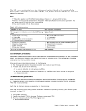
...: • "Numeric error codes" on page 40 • "Error messages" on page 42 • "No-beep symptoms" on page 42 • "LCD-related symptoms" on page 42 • "Intermittent problems" on page 43 • "Undetermined problems" on the hard disk. • The system is restored ...from hibernation mode and resumes operation. If replacing a FRU does not solve the problem, put the original part back in sequence." Wait a few seconds before resuming normal operation. To cause the computer...
...: • "Numeric error codes" on page 40 • "Error messages" on page 42 • "No-beep symptoms" on page 42 • "LCD-related symptoms" on page 42 • "Intermittent problems" on page 43 • "Undetermined problems" on the hard disk. • The system is restored ...from hibernation mode and resumes operation. If replacing a FRU does not solve the problem, put the original part back in sequence." Wait a few seconds before resuming normal operation. To cause the computer...
Hardware Maintenance Manual
Page 49
... 1 January, 2008 or later. • Lenovo will not provide replacement if the LCD is detected, replace the FRU shown by the computer. Reseat all ThinkPad Notebooks purchased on , and a blank LCD during POST. • LCD backlight not working. • LCD too dark. • LCD brightness cannot be adjusted. • LCD contrast cannot be adjusted. • LCD screen unreadable. • Characters missing...
... 1 January, 2008 or later. • Lenovo will not provide replacement if the LCD is detected, replace the FRU shown by the computer. Reseat all ThinkPad Notebooks purchased on , and a blank LCD during POST. • LCD backlight not working. • LCD too dark. • LCD brightness cannot be adjusted. • LCD contrast cannot be adjusted. • LCD screen unreadable. • Characters missing...

Hardware Maintenance Manual
Page 50
... you find the failing FRU. 7. b. Hard disk drive f. DIMM h. Devices attached to the docking station or the port replicator c. Battery pack e. If the problem remains, replace the following FRUs one at a time (do not replace a nondefective FRU): a. LCD assembly 44 Hardware Maintenance Manual System board b. External diskette drive or optical drive g.
... you find the failing FRU. 7. b. Hard disk drive f. DIMM h. Devices attached to the docking station or the port replicator c. Battery pack e. If the problem remains, replace the following FRUs one at a time (do not replace a nondefective FRU): a. LCD assembly 44 Hardware Maintenance Manual System board b. External diskette drive or optical drive g.

Hardware Maintenance Manual
Page 91
Removal steps of LCD bezel assembly 1 1 Step 1 Screw (quantity) M2 × 4 mm, wafer-head, nylon-coated (2) 2 1 Color Silver Torque 0.181 Nm (1.85 kgfcm) 2020 Integrated camera For access, remove these FRUs, in order: • "1010 Battery pack" on page 54 • "2010 LCD bezel assembly" on page 84 Chapter 8. Removing and replacing a FRU 85
Removal steps of LCD bezel assembly 1 1 Step 1 Screw (quantity) M2 × 4 mm, wafer-head, nylon-coated (2) 2 1 Color Silver Torque 0.181 Nm (1.85 kgfcm) 2020 Integrated camera For access, remove these FRUs, in order: • "1010 Battery pack" on page 54 • "2010 LCD bezel assembly" on page 84 Chapter 8. Removing and replacing a FRU 85

Hardware Maintenance Manual
Page 93
DO NOT press the surface of the panel or apply any excessive force to the cover, press the left and right edges covered with metal gently with your fingers. Chapter 8. Removing and replacing a FRU 87 2 1 1 3 3 3 3 Step 3 Screw (quantity) M2 × 4 mm, wafer-head, nylon-coated (6) Color Silver Torque 0.181 Nm (1.85 kgfcm) When installing: When attaching the LCD panel to the panel.
DO NOT press the surface of the panel or apply any excessive force to the cover, press the left and right edges covered with metal gently with your fingers. Chapter 8. Removing and replacing a FRU 87 2 1 1 3 3 3 3 Step 3 Screw (quantity) M2 × 4 mm, wafer-head, nylon-coated (6) Color Silver Torque 0.181 Nm (1.85 kgfcm) When installing: When attaching the LCD panel to the panel.

Hardware Maintenance Manual
Page 95
a : Wireless LAN AUX antenna (black) and wireless WAN AUX antenna (blue) b : Wireless LAN MAIN antenna (gray) and wireless WAN MAIN antenna (red) a b Chapter 8. Removing and replacing a FRU 89 Removal steps of antenna kit and LCD rear cover assembly 1 4 3 1 3 2 2 4 When installing: When you route the cables, make sure that they are not subjected to be broken. As you install the antenna kit, route the cables as shown in the figures below. Tension could cause the cables to be damaged by the cable guides, or a wire to any tension.
a : Wireless LAN AUX antenna (black) and wireless WAN AUX antenna (blue) b : Wireless LAN MAIN antenna (gray) and wireless WAN MAIN antenna (red) a b Chapter 8. Removing and replacing a FRU 89 Removal steps of antenna kit and LCD rear cover assembly 1 4 3 1 3 2 2 4 When installing: When you route the cables, make sure that they are not subjected to be broken. As you install the antenna kit, route the cables as shown in the figures below. Tension could cause the cables to be damaged by the cable guides, or a wire to any tension.

Hardware Maintenance Manual
Page 99
... as Self-service CRUs and others are available from Lenovo at http://www.lenovo.com/CRUs. CRU information and replacement instructions are shipped with the replacement CRU; Chapter 10. Installation of the service parts. • "Overall" on page 94 • "LCD FRUs" on page 108 • "Keyboard" on...available for all types or models, unless specific types or models are specified. • FRU with finger print reader and touchpad. - ThinkPad computers contain the following lists of Self-service CRUs is a Self-service CRU; Once the access panel is removed, the specific CRU ...
... as Self-service CRUs and others are available from Lenovo at http://www.lenovo.com/CRUs. CRU information and replacement instructions are shipped with the replacement CRU; Chapter 10. Installation of the service parts. • "Overall" on page 94 • "LCD FRUs" on page 108 • "Keyboard" on...available for all types or models, unless specific types or models are specified. • FRU with finger print reader and touchpad. - ThinkPad computers contain the following lists of Self-service CRUs is a Self-service CRU; Once the access panel is removed, the specific CRU ...


