User Manual
Page 5
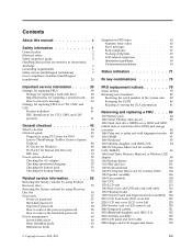
.... 58 How to remove the hard-disk password . . . . 59 Power management 60 Screen blank mode 60 Sleep (Standby) mode 60 Hibernation mode 61 © Copyright Lenovo 2008, 2009 Symptom-to-FRU index 62 Numeric error codes 62 Error messages 66 Beep symptoms 67 No-beep symptoms 67 LCD-related symptoms 68... the serial number of the system unit 80 Retaining the UUID 80 Reading or writing the ECA information . . . 81 Removing and replacing a FRU . . . . 83 1010 Battery pack 84 1020 Serial Ultrabay Slim device 85 1030 Hard disk drive (HDD) cover, HDD and HDD rubber rails or solid state drive...
.... 58 How to remove the hard-disk password . . . . 59 Power management 60 Screen blank mode 60 Sleep (Standby) mode 60 Hibernation mode 61 © Copyright Lenovo 2008, 2009 Symptom-to-FRU index 62 Numeric error codes 62 Error messages 66 Beep symptoms 67 No-beep symptoms 67 LCD-related symptoms 68... the serial number of the system unit 80 Retaining the UUID 80 Reading or writing the ECA information . . . 81 Removing and replacing a FRU . . . . 83 1010 Battery pack 84 1020 Serial Ultrabay Slim device 85 1030 Hard disk drive (HDD) cover, HDD and HDD rubber rails or solid state drive...
User Manual
Page 16
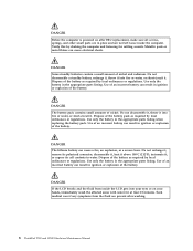
...Use of an incorrect battery can result in ignition or explosion of the battery. Dispose of the battery. Use only the battery in place and are in the appropriate parts listing. DANGER If the LCD breaks and the fluid from the fluid are present after FRU replacement, make sure all ...screws, springs, and other small parts are not left loose inside the LCD gets into your eyes or on after washing. 8 ThinkPad T500...
...Use of an incorrect battery can result in ignition or explosion of the battery. Dispose of the battery. Use only the battery in place and are in the appropriate parts listing. DANGER If the LCD breaks and the fluid from the fluid are present after FRU replacement, make sure all ...screws, springs, and other small parts are not left loose inside the LCD gets into your eyes or on after washing. 8 ThinkPad T500...
User Manual
Page 17
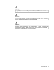
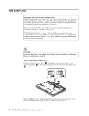
DANGER Unless hot swap is allowed for the FRU being replaced, do not remove the plastic cover that protects the lower part of the inverter card. DANGER Though the main batteries have low voltage, a shorted or grounded battery can produce enough current to burn personnel or combustible materials. DANGER To avoid shock, do as follows before removing it: power off the computer, unplug all power cords from electrical outlets, remove the battery pack, and disconnect any interconnecting cables. Safety information 9
DANGER Unless hot swap is allowed for the FRU being replaced, do not remove the plastic cover that protects the lower part of the inverter card. DANGER Though the main batteries have low voltage, a shorted or grounded battery can produce enough current to burn personnel or combustible materials. DANGER To avoid shock, do as follows before removing it: power off the computer, unplug all power cords from electrical outlets, remove the battery pack, and disconnect any interconnecting cables. Safety information 9

User Manual
Page 58
...program. Diagnostics --> CPU/Coprocessor 2. Interactive Tests --> Video Modem daughter card (MDC-3.0) 1. Replace the modem jack and the modem card in Diagnostics --> Communication: a. Then, run the... hard disk drive or Ultrabay hard disk drive. 6. Power Diagnostics --> ThinkPad Devices --> AC Adapter, Battery 1 (Battery2) LCD unit 1. PC Card slot ExpressCard slot Diagnostics ...system. Interactive Tests --> Diskette 50 ThinkPad T500 and W500 Hardware Maintenance Manual Conexant Smart Modem Interrupt b. Run Diagnostics --> ThinkPad Devices --> ExpressCard slot. While the ...
...program. Diagnostics --> CPU/Coprocessor 2. Interactive Tests --> Video Modem daughter card (MDC-3.0) 1. Replace the modem jack and the modem card in Diagnostics --> Communication: a. Then, run the... hard disk drive or Ultrabay hard disk drive. 6. Power Diagnostics --> ThinkPad Devices --> AC Adapter, Battery 1 (Battery2) LCD unit 1. PC Card slot ExpressCard slot Diagnostics ...system. Interactive Tests --> Diskette 50 ThinkPad T500 and W500 Hardware Maintenance Manual Conexant Smart Modem Interrupt b. Run Diagnostics --> ThinkPad Devices --> ExpressCard slot. While the ...
User Manual
Page 60
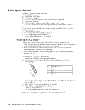
... turn on the computer. Disconnect the ac adapter and install the charged battery pack. 7. Note: Noise from the computer. 2. Remove the battery pack. 3. v If the power problem occurs only when the docking station or the port replicator is not correct, replace the AC adapter. 4. v If the power-on indicator does not turn... of the AC adapter cable. Connect the ac adapter. 4. Unplug the AC adapter cable from the AC adapter does not always indicate a defect. 52 ThinkPad T500 and W500 Hardware Maintenance Manual Measure the output voltage at the plug of the following : 1.
... turn on the computer. Disconnect the ac adapter and install the charged battery pack. 7. Note: Noise from the computer. 2. Remove the battery pack. 3. v If the power problem occurs only when the docking station or the port replicator is not correct, replace the AC adapter. 4. v If the power-on indicator does not turn... of the AC adapter cable. Connect the ac adapter. 4. Unplug the AC adapter cable from the AC adapter does not always indicate a defect. 52 ThinkPad T500 and W500 Hardware Maintenance Manual Measure the output voltage at the plug of the following : 1.
User Manual
Page 61
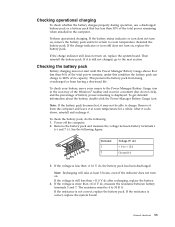
... when installed in the icon tray of its capacity. If the charge indicator or icon still does not turn on , replace the battery pack. If the charge indicator still does not turn on , replace the system board. Remove it return to 100% of the Windows® taskbar and wait for a while. Perform operational...
... when installed in the icon tray of its capacity. If the charge indicator or icon still does not turn on , replace the battery pack. If the charge indicator still does not turn on , replace the system board. Remove it return to 100% of the Windows® taskbar and wait for a while. Perform operational...
User Manual
Page 62
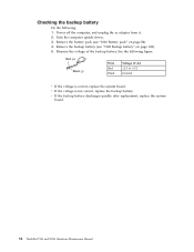
v If the voltage is correct, replace the system board. Remove the backup battery (see "1010 Battery pack" on page 100). 5. Measure the voltage of the backup battery. Turn the computer upside down. 3. v If the backup battery discharges quickly after replacement, replace the system board. 54 ThinkPad T500 and W500 Hardware Maintenance Manual Power off the computer, and unplug the ac...
v If the voltage is correct, replace the system board. Remove the backup battery (see "1010 Battery pack" on page 100). 5. Measure the voltage of the backup battery. Turn the computer upside down. 3. v If the backup battery discharges quickly after replacement, replace the system board. 54 ThinkPad T500 and W500 Hardware Maintenance Manual Power off the computer, and unplug the ac...
User Manual
Page 66
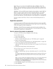
... on the ThinkPad Notebook. 3. The POP has been removed. 5. Reinstall the backup battery and the battery pack. (B) If an SVP has been set and is available, neither Lenovo nor Lenovo authorized service .... 2. Remove the backup battery. For models supporting the Passphrase function, press F1 while the POP icon is no SVP has been set . The user must be replaced for a scheduled fee. ...the battery pack, see "1100 Backup battery" on page 59. Turn off the computer. 2. For how to the system user. For the other models, enter the POP. Select Password. 58 ThinkPad T500 and...
... on the ThinkPad Notebook. 3. The POP has been removed. 5. Reinstall the backup battery and the battery pack. (B) If an SVP has been set and is available, neither Lenovo nor Lenovo authorized service .... 2. Remove the backup battery. For models supporting the Passphrase function, press F1 while the POP icon is no SVP has been set . The user must be replaced for a scheduled fee. ...the battery pack, see "1100 Backup battery" on page 59. Turn off the computer. 2. For how to the system user. For the other models, enter the POP. Select Password. 58 ThinkPad T500 and...

User Manual
Page 72
...Replace the backup battery and run BIOS Setup Utility to reset the time and date. 3. Load "Setup Default" in BIOS Setup Utility. 2. CPU. 2. Load Setup Defaults in BIOS Setup Utility. 2. Remove Mini PCI network card. 2. in-Turn off and remove the miniPCI network card. 1. System board. 64 ThinkPad T500... and W500 Hardware Maintenance Manual Table 2. System board. 02F6 Software NMI failed 1. System board. 1802 Unauthorized network card is dead. 1. System board. 1803 1. Charge the backup battery for more than 8 hours ...
...Replace the backup battery and run BIOS Setup Utility to reset the time and date. 3. Load "Setup Default" in BIOS Setup Utility. 2. CPU. 2. Load Setup Defaults in BIOS Setup Utility. 2. Remove Mini PCI network card. 2. in-Turn off and remove the miniPCI network card. 1. System board. 64 ThinkPad T500... and W500 Hardware Maintenance Manual Table 2. System board. 02F6 Software NMI failed 1. System board. 1802 Unauthorized network card is dead. 1. System board. 1803 1. Charge the backup battery for more than 8 hours ...

User Manual
Page 77
... failing FRU. 7. If no error is detected, replace the FRU shown by the computer. If any error is detected, do with a hardware defect, such as cosmic radiation, electrostatic discharge, or software errors. Battery pack e. DIMM h. Verify that no defects). Hard disk drive f. PC Cards 4. Non-ThinkPad devices b. Intermittent problems Intermittent system hang problems...
... failing FRU. 7. If no error is detected, replace the FRU shown by the computer. If any error is detected, do with a hardware defect, such as cosmic radiation, electrostatic discharge, or software errors. Battery pack e. DIMM h. Verify that no defects). Hard disk drive f. PC Cards 4. Non-ThinkPad devices b. Intermittent problems Intermittent system hang problems...

User Manual
Page 91
...as given in the drawings by the numbers in removing and replacing a FRU. DANGER Before removing any FRU, turn on the computer until you have made sure that all power cords from electrical outlets, remove the battery pack, and then disconnect any notes that have to observe ...with one hand or by using an electrostatic discharge (ESD) strap (P/N 6405959). © Copyright Lenovo 2008, 2009 83 Before touching it in the direction as shown in the drawing. 7. Removing and replacing a FRU This chapter presents directions and drawings for use the correct screw as given by the arrow...
...as given in the drawings by the numbers in removing and replacing a FRU. DANGER Before removing any FRU, turn on the computer until you have made sure that all power cords from electrical outlets, remove the battery pack, and then disconnect any notes that have to observe ...with one hand or by using an electrostatic discharge (ESD) strap (P/N 6405959). © Copyright Lenovo 2008, 2009 83 Before touching it in the direction as shown in the drawing. 7. Removing and replacing a FRU This chapter presents directions and drawings for use the correct screw as given by the arrow...
User Manual
Page 92
... this diagnostic shows that determines if the battery pack is in the locked position. 84 ThinkPad T500 and W500 Hardware Maintenance Manual Note that the battery release lever is defective. DANGER Use only the battery specified in the parts list for replacing a battery pack: ThinkVantage Toolbox (in Windows 7) and Lenovo System Toolbox (in the direction shown by arrow...
... this diagnostic shows that determines if the battery pack is in the locked position. 84 ThinkPad T500 and W500 Hardware Maintenance Manual Note that the battery release lever is defective. DANGER Use only the battery specified in the parts list for replacing a battery pack: ThinkVantage Toolbox (in Windows 7) and Lenovo System Toolbox (in the direction shown by arrow...
User Manual
Page 96
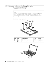
If the fingerprint reader has any defects, you can replace it by the procedures given in this FRU in order: v "1010 Battery pack" on page 84 Note: In models with or without a fingerprint reader. Table 12. 1040 Palm rest or palm rest with fingerprint reader For access, .... Removal steps of palm rest 1 1 1 1 Step 1 Icon Screw (quantity) M2 × 14 mm, wafer-head, nylon-coated (4) Color Black Torque 0.189 Nm (1.85 kgfcm) 2 88 ThinkPad T500 and W500 Hardware Maintenance Manual
If the fingerprint reader has any defects, you can replace it by the procedures given in this FRU in order: v "1010 Battery pack" on page 84 Note: In models with or without a fingerprint reader. Table 12. 1040 Palm rest or palm rest with fingerprint reader For access, .... Removal steps of palm rest 1 1 1 1 Step 1 Icon Screw (quantity) M2 × 14 mm, wafer-head, nylon-coated (4) Color Black Torque 0.189 Nm (1.85 kgfcm) 2 88 ThinkPad T500 and W500 Hardware Maintenance Manual
User Manual
Page 99
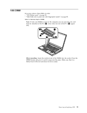
... DIMM Note: If only one DIMM is used on page 88 Table 14. Removing and replacing a FRU 91 Make sure that it snaps into the socket. 1050 DIMM For access, remove these FRUs in order: v "1010 Battery pack" on page 84 v "1040 Palm rest or palm rest with fingerprint reader" on the...
... DIMM Note: If only one DIMM is used on page 88 Table 14. Removing and replacing a FRU 91 Make sure that it snaps into the socket. 1050 DIMM For access, remove these FRUs in order: v "1010 Battery pack" on page 84 v "1040 Palm rest or palm rest with fingerprint reader" on the...

User Manual
Page 109
After you finish the servicing, make sure that you start the servicing. Removing and replacing a FRU 101 Removal steps of SIM card slot 1 2 Step 1 Screw (quantity) Color M2 × 3.5 mm, wafer-head, nylon-coated (1) Silver Torque 0.189 Nm (1.85 kgfcm) ...When installing: Make sure the connector 2 is attached firmly. Table 20. 1110 SIM card slot For access, remove these FRUs, in order: v "1010 Battery pack" on page 84 v "1040 Palm rest or palm rest with fingerprint reader" on page 88 v "1060 Keyboard" on page 92 Note: If the SIM...
After you finish the servicing, make sure that you start the servicing. Removing and replacing a FRU 101 Removal steps of SIM card slot 1 2 Step 1 Screw (quantity) Color M2 × 3.5 mm, wafer-head, nylon-coated (1) Silver Torque 0.189 Nm (1.85 kgfcm) ...When installing: Make sure the connector 2 is attached firmly. Table 20. 1110 SIM card slot For access, remove these FRUs, in order: v "1010 Battery pack" on page 84 v "1040 Palm rest or palm rest with fingerprint reader" on page 88 v "1060 Keyboard" on page 92 Note: If the SIM...
User Manual
Page 121
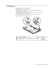
1170 LCD unit For access, remove these FRUs in order: v "1010 Battery pack" on page 84 v "1040 Palm rest or palm rest with fingerprint reader" on page 88 v "1060 Keyboard" on page 92 v "1080 PCI Express Mini Card for wireless LAN/WiMAX" on page 96 v "1120 Keyboard bezel" on page 102 v "1130 PCI Express Mini Card for wireless WAN" on page 104 Table 28. Removal steps of LCD assembly 1 1 Step 1 Screw (quantity) M2.5 × 6.5 mm, wafer-head, nylon-coated (2) Color Black Torque 0.392 Nm (4 kgfcm) Removing and replacing a FRU 113
1170 LCD unit For access, remove these FRUs in order: v "1010 Battery pack" on page 84 v "1040 Palm rest or palm rest with fingerprint reader" on page 88 v "1060 Keyboard" on page 92 v "1080 PCI Express Mini Card for wireless LAN/WiMAX" on page 96 v "1120 Keyboard bezel" on page 102 v "1130 PCI Express Mini Card for wireless WAN" on page 104 Table 28. Removal steps of LCD assembly 1 1 Step 1 Screw (quantity) M2.5 × 6.5 mm, wafer-head, nylon-coated (2) Color Black Torque 0.392 Nm (4 kgfcm) Removing and replacing a FRU 113
User Manual
Page 129
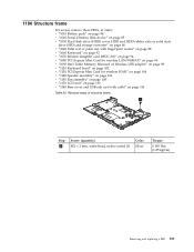
1190 Structure frame For access, remove these FRUs, in order: v "1010 Battery pack" on page 84 v "1020 Serial Ultrabay Slim device" on page 85 v "1030 Hard disk drive (HDD) cover, HDD and HDD rubber rails or solid ... 30. Removal steps of structure frame 1 Step 1 Screw (quantity) M2 × 3 mm, wafer-head, nylon-coated (1) Color Silver Torque 0.189 Nm (1.85 kgfcm) Removing and replacing a FRU 121
1190 Structure frame For access, remove these FRUs, in order: v "1010 Battery pack" on page 84 v "1020 Serial Ultrabay Slim device" on page 85 v "1030 Hard disk drive (HDD) cover, HDD and HDD rubber rails or solid ... 30. Removal steps of structure frame 1 Step 1 Screw (quantity) M2 × 3 mm, wafer-head, nylon-coated (1) Color Silver Torque 0.189 Nm (1.85 kgfcm) Removing and replacing a FRU 121
User Manual
Page 133
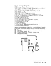
... Following components soldered on page 102 v "1130 PCI Express Mini Card for the HDD Active Protection System™ e ICH (I/O Controller Hub) a b e c d Removing and replacing a FRU 125 When you service the system board, avoid any kind of the system board are extremely sensitive. a CPU b Video chip c MCH (Memory Controller Hub...Mini Card for wireless LAN/WiMAX" on page 96 v "1090 Intel Turbo Memory Minicard or Wireless USB adapter" on page 98 v "1100 Backup battery" on page 100 v "1110 SIM card slot" on page 101 v "1120 Keyboard bezel" on the top side of rough handling.
... Following components soldered on page 102 v "1130 PCI Express Mini Card for the HDD Active Protection System™ e ICH (I/O Controller Hub) a b e c d Removing and replacing a FRU 125 When you service the system board, avoid any kind of the system board are extremely sensitive. a CPU b Video chip c MCH (Memory Controller Hub...Mini Card for wireless LAN/WiMAX" on page 96 v "1090 Intel Turbo Memory Minicard or Wireless USB adapter" on page 98 v "1100 Backup battery" on page 100 v "1110 SIM card slot" on page 101 v "1120 Keyboard bezel" on the top side of rough handling.

User Manual
Page 135
Removal steps of LCD front bezel 2 1 2 1 1 1 Step 1 2 Screw cap Screw (quantity) M2.5 × 6.5 mm, bind-head, nylon-coated (3) M2.5 × 6.5 mm, bind-head, nylon-coated (2) Color Black Black Torque 0.392 Nm (4 kgfcm) 0.392 Nm (4 kgfcm) Removing and replacing a FRU 127 2010 LCD front bezel (LCD cover kit) For access, remove this FRU: v "1010 Battery pack" on page 84 Table 32.
Removal steps of LCD front bezel 2 1 2 1 1 1 Step 1 2 Screw cap Screw (quantity) M2.5 × 6.5 mm, bind-head, nylon-coated (3) M2.5 × 6.5 mm, bind-head, nylon-coated (2) Color Black Black Torque 0.392 Nm (4 kgfcm) 0.392 Nm (4 kgfcm) Removing and replacing a FRU 127 2010 LCD front bezel (LCD cover kit) For access, remove this FRU: v "1010 Battery pack" on page 84 Table 32.
User Manual
Page 137
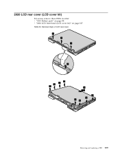
Removal steps of LCD rear cover 1 1 1 2 3 3 3 3 4 33 3 3 Removing and replacing a FRU 129 2020 LCD rear cover (LCD cover kit) For access, remove these FRUs in order: v "1010 Battery pack" on page 84 v "2010 LCD front bezel (LCD cover kit)" on page 127 Table 33.
Removal steps of LCD rear cover 1 1 1 2 3 3 3 3 4 33 3 3 Removing and replacing a FRU 129 2020 LCD rear cover (LCD cover kit) For access, remove these FRUs in order: v "1010 Battery pack" on page 84 v "2010 LCD front bezel (LCD cover kit)" on page 127 Table 33.


