
Hardware Maintenance Manual
Page 4
... for wireless WAN or mSATA solid-state drive 73 1080 PCI Express Mini Card for wireless LAN/WiMAX 79 1090 Backup battery 81 1100 Keyboard bezel 82 1110 ExpressCard reader board or ExpressCard dummy card 85 1120 Bluetooth daughter card 87 1130 I/O sub card 88 1140 Speaker assembly 89 1150 Thermal... 1170 DC-in connector and base cover assembly . 94 1180 System board assembly and RJ45 sub card 96 2010 LCD unit 100 2020 LCD front bezel 102 2030 LED sub card 102 2040 Integrated camera 103 2050 Antenna assembly 105 2060 LCD panel, hinges, and LCD rear cover assembly 106 Appendix...
... for wireless WAN or mSATA solid-state drive 73 1080 PCI Express Mini Card for wireless LAN/WiMAX 79 1090 Backup battery 81 1100 Keyboard bezel 82 1110 ExpressCard reader board or ExpressCard dummy card 85 1120 Bluetooth daughter card 87 1130 I/O sub card 88 1140 Speaker assembly 89 1150 Thermal... 1170 DC-in connector and base cover assembly . 94 1180 System board assembly and RJ45 sub card 96 2010 LCD unit 100 2020 LCD front bezel 102 2030 LED sub card 102 2040 Integrated camera 103 2050 Antenna assembly 105 2060 LCD panel, hinges, and LCD rear cover assembly 106 Appendix...

Hardware Maintenance Manual
Page 60
Description Self-service CRU Optional-service CRU 1 LCD unit No No 2 PCI Express Mini Card for wireless LAN/WiMAX No Yes 3 Memory module (under the keyboard) No Yes 4 Keyboard bezel No No 5 DC-in cable No No 6 RJ45 sub card and Always On USB connector board No No 7 Microprocessor No No 54 Hardware Maintenance Manual Major FRUs and CRUs 1 27 26 2 3 25 4 24 23 5 22 6 21 7 20 19 8 18 9 10 11 17 12 16 15 13 14 No.
Description Self-service CRU Optional-service CRU 1 LCD unit No No 2 PCI Express Mini Card for wireless LAN/WiMAX No Yes 3 Memory module (under the keyboard) No Yes 4 Keyboard bezel No No 5 DC-in cable No No 6 RJ45 sub card and Always On USB connector board No No 7 Microprocessor No No 54 Hardware Maintenance Manual Major FRUs and CRUs 1 27 26 2 3 25 4 24 23 5 22 6 21 7 20 19 8 18 9 10 11 17 12 16 15 13 14 No.

Hardware Maintenance Manual
Page 62
Description 1 LCD front bezel 2 Built-in camera (on some models) 3 LCD panel 4 Hinge kit 5 Antenna kit 6 LCD rear cover assembly 56 Hardware Maintenance Manual Self-service CRU No No No No No No Optional-service CRU No No No No No No LCD FRUs and CRUs 1 2 3 4 9 8 7 5 6 No.
Description 1 LCD front bezel 2 Built-in camera (on some models) 3 LCD panel 4 Hinge kit 5 Antenna kit 6 LCD rear cover assembly 56 Hardware Maintenance Manual Self-service CRU No No No No No No Optional-service CRU No No No No No No LCD FRUs and CRUs 1 2 3 4 9 8 7 5 6 No.

Hardware Maintenance Manual
Page 76
Step 1 Screw (quantity) M2 × 14 mm, flat-head, nylon-coated (2) Color Black Torque 0.181 Nm (1.85 kgfcm) Press the keyboard as shown in the following illustration until the hooks on the rear edge of keyboard 1 1 When installing: Ensure that the screws are detached from the keyboard bezel. 2 2 Lift the keyboard up 3 , and then detach the keyboard connectors 4 . 70 Hardware Maintenance Manual Removal steps of the keyboard are fastened and the keyboard is secured.
Step 1 Screw (quantity) M2 × 14 mm, flat-head, nylon-coated (2) Color Black Torque 0.181 Nm (1.85 kgfcm) Press the keyboard as shown in the following illustration until the hooks on the rear edge of keyboard 1 1 When installing: Ensure that the screws are detached from the keyboard bezel. 2 2 Lift the keyboard up 3 , and then detach the keyboard connectors 4 . 70 Hardware Maintenance Manual Removal steps of the keyboard are fastened and the keyboard is secured.
Hardware Maintenance Manual
Page 78
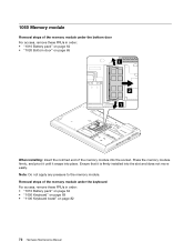
... bottom door For access, remove these FRUs in order: • "1010 Battery pack" on page 64 • "1050 Keyboard" on page 69 • "1100 Keyboard bezel" on page 82 72 Hardware Maintenance Manual
... bottom door For access, remove these FRUs in order: • "1010 Battery pack" on page 64 • "1050 Keyboard" on page 69 • "1100 Keyboard bezel" on page 82 72 Hardware Maintenance Manual

Hardware Maintenance Manual
Page 88
2 1 When installing: Ensure that the battery connector is attached firmly to the system board. 1100 Keyboard bezel For access, remove these FRUs in order: • "1010 Battery pack" on page 64 • "1020 Bottom door" on page 65 • "1030 Optical drive" on page 66 • "1040 Hard disk drive or solid-state drive assembly" on page 68 • "1050 Keyboard" on page 69 82 Hardware Maintenance Manual
2 1 When installing: Ensure that the battery connector is attached firmly to the system board. 1100 Keyboard bezel For access, remove these FRUs in order: • "1010 Battery pack" on page 64 • "1020 Bottom door" on page 65 • "1030 Optical drive" on page 66 • "1040 Hard disk drive or solid-state drive assembly" on page 68 • "1050 Keyboard" on page 69 82 Hardware Maintenance Manual

Hardware Maintenance Manual
Page 89
Removing or replacing a FRU 83 Removal steps of keyboard bezel 2 1 21 1 1 2 2 2 2 22 2 1 1 Step 1 2 Screw (quantity) M2 × 5 mm, flat-head, nylon-coated (6) M2 × 3 mm, flat-head, nylon-coated (9) Color Black Black Torque 0.392 Nm (4 kgfcm) 0.181 Nm (1.85 kgfcm) 3 3 3 Step 3 Screw (quantity) M2 × 8 mm, flat-head, nylon-coated (3) Color Black Torque 0.181 Nm (1.85 kgfcm) Chapter 9.
Removing or replacing a FRU 83 Removal steps of keyboard bezel 2 1 21 1 1 2 2 2 2 22 2 1 1 Step 1 2 Screw (quantity) M2 × 5 mm, flat-head, nylon-coated (6) M2 × 3 mm, flat-head, nylon-coated (9) Color Black Black Torque 0.392 Nm (4 kgfcm) 0.181 Nm (1.85 kgfcm) 3 3 3 Step 3 Screw (quantity) M2 × 8 mm, flat-head, nylon-coated (3) Color Black Torque 0.181 Nm (1.85 kgfcm) Chapter 9.
Hardware Maintenance Manual
Page 91
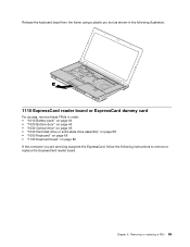
Chapter 9. Removing or replacing a FRU 85 Release the keyboard bezel from the frame using a plastic pry tool as shown in the following illustration. 10 1110 ExpressCard reader board or ExpressCard dummy card For access, remove ..." on page 66 • "1040 Hard disk drive or solid-state drive assembly" on page 68 • "1050 Keyboard" on page 69 • "1100 Keyboard bezel" on page 82 If the computer you are servicing supports the ExpressCard, follow the following instructions to remove or replace the ExpressCard reader board.
Chapter 9. Removing or replacing a FRU 85 Release the keyboard bezel from the frame using a plastic pry tool as shown in the following illustration. 10 1110 ExpressCard reader board or ExpressCard dummy card For access, remove ..." on page 66 • "1040 Hard disk drive or solid-state drive assembly" on page 68 • "1050 Keyboard" on page 69 • "1100 Keyboard bezel" on page 82 If the computer you are servicing supports the ExpressCard, follow the following instructions to remove or replace the ExpressCard reader board.
Hardware Maintenance Manual
Page 94
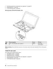
• "1040 Hard disk drive or solid-state drive assembly" on page 68 • "1050 Keyboard" on page 69 • "1100 Keyboard bezel" on page 82 Removal steps of bluetooth daughter card 1 2 Step 1 Screw (quantity) M2 × 3 mm, flat-head, nylon-coated (1) Color Black Torque 0.181 Nm (1.85 ..." on page 66 • "1040 Hard disk drive or solid-state drive assembly" on page 68 • "1050 Keyboard" on page 69 • "1100 Keyboard bezel" on page 82 88 Hardware Maintenance Manual
• "1040 Hard disk drive or solid-state drive assembly" on page 68 • "1050 Keyboard" on page 69 • "1100 Keyboard bezel" on page 82 Removal steps of bluetooth daughter card 1 2 Step 1 Screw (quantity) M2 × 3 mm, flat-head, nylon-coated (1) Color Black Torque 0.181 Nm (1.85 ..." on page 66 • "1040 Hard disk drive or solid-state drive assembly" on page 68 • "1050 Keyboard" on page 69 • "1100 Keyboard bezel" on page 82 88 Hardware Maintenance Manual

Hardware Maintenance Manual
Page 96
• "1020 Bottom door" on page 65 • "1030 Optical drive" on page 66 • "1040 Hard disk drive or solid-state drive assembly" on page 68 • "1050 Keyboard" on page 69 • "1100 Keyboard bezel" on page 82 Removal steps of speaker assembly 1 2 2 3 2 2 3 90 Hardware Maintenance Manual
• "1020 Bottom door" on page 65 • "1030 Optical drive" on page 66 • "1040 Hard disk drive or solid-state drive assembly" on page 68 • "1050 Keyboard" on page 69 • "1100 Keyboard bezel" on page 82 Removal steps of speaker assembly 1 2 2 3 2 2 3 90 Hardware Maintenance Manual

Hardware Maintenance Manual
Page 97
..." on page 66 • "1040 Hard disk drive or solid-state drive assembly" on page 68 • "1050 Keyboard" on page 69 • "1100 Keyboard bezel" on page 82 Attention: • Do not handle the thermal fan assembly roughly.
..." on page 66 • "1040 Hard disk drive or solid-state drive assembly" on page 68 • "1050 Keyboard" on page 69 • "1100 Keyboard bezel" on page 82 Attention: • Do not handle the thermal fan assembly roughly.

Hardware Maintenance Manual
Page 99
... drive or solid-state drive assembly" on page 68 • "1050 Keyboard" on page 69 • "1090 Backup battery" on page 81 • "1100 Keyboard bezel" on page 82 • "1150 Thermal fan assembly" on page 91 Attention: The microprocessor is extremely sensitive. Chapter 9. Removing or replacing a FRU 93 When you...
... drive or solid-state drive assembly" on page 68 • "1050 Keyboard" on page 69 • "1090 Backup battery" on page 81 • "1100 Keyboard bezel" on page 82 • "1150 Thermal fan assembly" on page 91 Attention: The microprocessor is extremely sensitive. Chapter 9. Removing or replacing a FRU 93 When you...

Hardware Maintenance Manual
Page 100
... in order: • "1010 Battery pack" on page 64 • "1030 Optical drive" on page 66 • "1050 Keyboard" on page 69 • "1100 Keyboard bezel" on page 82 • "2010 LCD unit" on page 100 94 Hardware Maintenance Manual then remove the microprocessor 2 . Removal steps of microprocessor Rotate the head...
... in order: • "1010 Battery pack" on page 64 • "1030 Optical drive" on page 66 • "1050 Keyboard" on page 69 • "1100 Keyboard bezel" on page 82 • "2010 LCD unit" on page 100 94 Hardware Maintenance Manual then remove the microprocessor 2 . Removal steps of microprocessor Rotate the head...

Hardware Maintenance Manual
Page 103
...; "1080 PCI Express Mini Card for wireless LAN/WiMAX" on page 79 • "1090 Backup battery" on page 81 • "1100 Keyboard bezel" on page 82 • "1110 ExpressCard reader board or ExpressCard dummy card" on page 85 • "1120 Bluetooth daughter card " on page ...(PCH) c Graphic Processing Unit (GPU) Note: GPU is only for the hard disk drive Active Protection System® (APS) For ThinkPad L430 models (top side view): a c b For ThinkPad L430 models (bottom side view): d Chapter 9. d Accelerometer chip for models that have a discrete graphics card. When you service the system board...
...; "1080 PCI Express Mini Card for wireless LAN/WiMAX" on page 79 • "1090 Backup battery" on page 81 • "1100 Keyboard bezel" on page 82 • "1110 ExpressCard reader board or ExpressCard dummy card" on page 85 • "1120 Bluetooth daughter card " on page ...(PCH) c Graphic Processing Unit (GPU) Note: GPU is only for the hard disk drive Active Protection System® (APS) For ThinkPad L430 models (top side view): a c b For ThinkPad L430 models (bottom side view): d Chapter 9. d Accelerometer chip for models that have a discrete graphics card. When you service the system board...
Hardware Maintenance Manual
Page 108
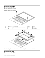
Then secure the bezel with the screws. 2030 LED sub card For access, remove these FRUs in order: 102 Hardware Maintenance Manual 2020 LCD front bezel For access, remove this FRU: • "1010 Battery pack" on page 64 Removal steps of LCD front bezel 1 1 Step 1 Screw cap Screw (quantity) M2.5 × 6 mm, flat-head, nylon-coated (2) 2 2 2 2 2 2 2 Color Black Torque 0.392 Nm (4.00 kgfcm) 2 2 2 2 When installing: Ensure that all the latches are attached firmly.
Then secure the bezel with the screws. 2030 LED sub card For access, remove these FRUs in order: 102 Hardware Maintenance Manual 2020 LCD front bezel For access, remove this FRU: • "1010 Battery pack" on page 64 Removal steps of LCD front bezel 1 1 Step 1 Screw cap Screw (quantity) M2.5 × 6 mm, flat-head, nylon-coated (2) 2 2 2 2 2 2 2 Color Black Torque 0.392 Nm (4.00 kgfcm) 2 2 2 2 When installing: Ensure that all the latches are attached firmly.

Hardware Maintenance Manual
Page 109
Removing or replacing a FRU 103 • "1010 Battery pack" on page 64 • "2020 LCD front bezel" on page 102 Removal steps of LED sub card 1 Step 1 Screw (quantity) M2 × 3.5 mm, flat-head, nylon-coated (1) Color Black Torque 0.181 Nm (1.85 kgfcm) 2040 Integrated camera For access, remove these FRUs in order: • "1010 Battery pack" on page 64 • "2020 LCD front bezel" on page 102 3 2 Chapter 9.
Removing or replacing a FRU 103 • "1010 Battery pack" on page 64 • "2020 LCD front bezel" on page 102 Removal steps of LED sub card 1 Step 1 Screw (quantity) M2 × 3.5 mm, flat-head, nylon-coated (1) Color Black Torque 0.181 Nm (1.85 kgfcm) 2040 Integrated camera For access, remove these FRUs in order: • "1010 Battery pack" on page 64 • "2020 LCD front bezel" on page 102 3 2 Chapter 9.

Hardware Maintenance Manual
Page 111
... Antenna assembly For access, remove these FRUs in order: • "1010 Battery pack" on page 64 • "1050 Keyboard" on page 69 • "1100 Keyboard bezel" on page 82 • "1070 PCI Express Mini Card for wireless WAN or mSATA solid-state drive" on page 73 • "1080 PCI Express Mini... Card for wireless LAN/WiMAX" on page 79 • "2010 LCD unit" on page 100 • "2020 LCD front bezel" on page 102 • "2040 Integrated camera" on page 103 Removal steps of antenna assembly Release the antenna cables from the cable guides of the...
... Antenna assembly For access, remove these FRUs in order: • "1010 Battery pack" on page 64 • "1050 Keyboard" on page 69 • "1100 Keyboard bezel" on page 82 • "1070 PCI Express Mini Card for wireless WAN or mSATA solid-state drive" on page 73 • "1080 PCI Express Mini... Card for wireless LAN/WiMAX" on page 79 • "2010 LCD unit" on page 100 • "2020 LCD front bezel" on page 102 • "2040 Integrated camera" on page 103 Removal steps of antenna assembly Release the antenna cables from the cable guides of the...

Hardware Maintenance Manual
Page 112
... page 82 • "2010 LCD unit" on page 100 • "2020 LCD front bezel" on page 102 Removal steps of LCD panel, hinges, and LCD rear cover assembly for L430 models Remove the screws 1 that they are not subject to be damaged by the cable guides, or a wire to any tension. When...
... page 82 • "2010 LCD unit" on page 100 • "2020 LCD front bezel" on page 102 Removal steps of LCD panel, hinges, and LCD rear cover assembly for L430 models Remove the screws 1 that they are not subject to be damaged by the cable guides, or a wire to any tension. When...

(English) User Guide
Page 15
...the palm rest for any part of overheating. • Airflow temperatures into the computer should not exceed 35°C (95°F). © Copyright Lenovo 2012 xiii For your safety, always follow these basic precautions: • When your computer is turned on a bed, sofa, carpet, or other ... with your computer inside furniture, as this might increase the risk of your computer or charge the battery near flammable materials or in the bezel. Avoid keeping your hands, your body in . • Regularly inspect the outside of the computer for dust accumulation. • Remove ...
...the palm rest for any part of overheating. • Airflow temperatures into the computer should not exceed 35°C (95°F). © Copyright Lenovo 2012 xiii For your safety, always follow these basic precautions: • When your computer is turned on a bed, sofa, carpet, or other ... with your computer inside furniture, as this might increase the risk of your computer or charge the battery near flammable materials or in the bezel. Avoid keeping your hands, your body in . • Regularly inspect the outside of the computer for dust accumulation. • Remove ...
