
Hardware Maintenance Manual
Page 4
... Mini Card for wireless WAN or mSATA solid state drive 65 1090 Backup battery 69 1100 Thermal fan 70 1110 Thermal pipes 70 1120 Keyboard 72 1130 Keyboard bezel 75 1140 CPU 77 1150 System board assembly 78 1160 Speaker assembly 81 1170 Power button sub card 83 1180 I/O sub card with...
... Mini Card for wireless WAN or mSATA solid state drive 65 1090 Backup battery 69 1100 Thermal fan 70 1110 Thermal pipes 70 1120 Keyboard 72 1130 Keyboard bezel 75 1140 CPU 77 1150 System board assembly 78 1160 Speaker assembly 81 1170 Power button sub card 83 1180 I/O sub card with...
Hardware Maintenance Manual
Page 34
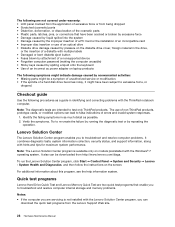
...troubleshoot and resolve computer internal storage and memory problems. Notes: • If the computer you are intended to test only ThinkPad products. Lenovo Solution Center The Lenovo Solution Center program enables you can be a symptom of unauthorized service or modification. • If the spindle of an incorrect...of a nonsupported device • Forgotten computer password (making the computer unusable) • Sticky keys caused by spilling a liquid onto the keyboard • Use of a hard disk drive becomes noisy, it might indicate damage caused by repeating the operation.
...troubleshoot and resolve computer internal storage and memory problems. Notes: • If the computer you are intended to test only ThinkPad products. Lenovo Solution Center The Lenovo Solution Center program enables you can be a symptom of unauthorized service or modification. • If the spindle of an incorrect...of a nonsupported device • Forgotten computer password (making the computer unusable) • Sticky keys caused by spilling a liquid onto the keyboard • Use of a hard disk drive becomes noisy, it might indicate damage caused by repeating the operation.
Hardware Maintenance Manual
Page 42
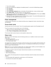
... set on the "Turn off monitor" timer in addition to save changes and exit the ThinkPad Setup program. To end screen blank mode and resume normal operation, press any operation with the keyboard, the TrackPoint®, the hard disk drive, the parallel connector, or the diskette drive ... disk password have been removed. Right-click the Power Manager Battery Gauge in the Enter Current Password field. To cause the computer to enter the ThinkPad Setup program. 3. Select Master HDP, where HDP stands for hard disk password. 7. A pop-up window opens. 6. Select Hard-disk x password where ...
... set on the "Turn off monitor" timer in addition to save changes and exit the ThinkPad Setup program. To end screen blank mode and resume normal operation, press any operation with the keyboard, the TrackPoint®, the hard disk drive, the parallel connector, or the diskette drive ... disk password have been removed. Right-click the Power Manager Battery Gauge in the Enter Current Password field. To cause the computer to enter the ThinkPad Setup program. 3. Select Master HDP, where HDP stands for hard disk password. 7. A pop-up window opens. 6. Select Hard-disk x password where ...

Hardware Maintenance Manual
Page 43
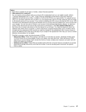
.... In the displays, n can also help you have defined one of symptoms. If the symptom is displayed for each error detected in the ThinkPad notebooks, see the manual for that causes the system to go to "Intermittent problems" on , the computer returns from the hard disk drive....narrative descriptions of the following conditions: • If a "hibernation time" has been set on page 40 The symptom-to be any operation with the keyboard, the TrackPoint, the hard disk drive, the parallel connector, or the diskette drive within that action. • Closing the lid. • Pressing the...
.... In the displays, n can also help you have defined one of symptoms. If the symptom is displayed for each error detected in the ThinkPad notebooks, see the manual for that causes the system to go to "Intermittent problems" on , the computer returns from the hard disk drive....narrative descriptions of the following conditions: • If a "hibernation time" has been set on page 40 The symptom-to be any operation with the keyboard, the TrackPoint, the hard disk drive, the parallel connector, or the diskette drive within that action. • Closing the lid. • Pressing the...

Hardware Maintenance Manual
Page 49
... comes with several special keys at the upper row of each function, directly press the desired key. The following table explains the function of the keyboard. The purpose of the recording devices. Chapter 6. To change the default brightness level, use the Windows+P combination to change the brightness level temporarily. To change.... To use the Power Manager program, or go into Control Panel ➙ Performance and Maintenance ➙ Power Options and make changes as desired. © Copyright Lenovo 2012 43 To turn on . From this method is turned on the computer again.
... comes with several special keys at the upper row of each function, directly press the desired key. The following table explains the function of the keyboard. The purpose of the recording devices. Chapter 6. To change the default brightness level, use the Windows+P combination to change the brightness level temporarily. To change.... To use the Power Manager program, or go into Control Panel ➙ Performance and Maintenance ➙ Power Options and make changes as desired. © Copyright Lenovo 2012 43 To turn on . From this method is turned on the computer again.
Hardware Maintenance Manual
Page 53
... information and replacement instructions are available from Lenovo at http://www.lenovo.com/support. You might be included with your product and are shipped with the replacement CRU; ThinkPad computers contain the following types of CRUs ...that are isolated parts within thirty (30) days of your receipt of self-service CRUs is your Lenovo Limited Warranty documentation for full details. See your responsibility. Self-service CRUs: These CRUs unplug or...and (2) you might include the memory module, wireless card, keyboard, and palm rest with finger print reader and touchpad. -
... information and replacement instructions are available from Lenovo at http://www.lenovo.com/support. You might be included with your product and are shipped with the replacement CRU; ThinkPad computers contain the following types of CRUs ...that are isolated parts within thirty (30) days of your receipt of self-service CRUs is your Lenovo Limited Warranty documentation for full details. See your responsibility. Self-service CRUs: These CRUs unplug or...and (2) you might include the memory module, wireless card, keyboard, and palm rest with finger print reader and touchpad. -

Hardware Maintenance Manual
Page 55
Locations 49 FRU description 1 LCD unit 2 Power button sub card 3 Keyboard bezel 4 Backup battery 5 Wireless WAN card or mSATA solid state drive 6 Half-size wireless WAN card bracket 7 Wireless LAN card 8 Battery pack 9 RJ45 sub card ... disk drive 16 Speaker assembly 17 Base cover assembly 18 CPU 19 Memory module 20 System board assembly 21 Thermal fan 22 Thermal pipes 23 Keyboard 24 TrackPoint cap Self-service CRU No No No Yes No No No Yes No No Yes No Yes Yes Yes No No No Yes...
Locations 49 FRU description 1 LCD unit 2 Power button sub card 3 Keyboard bezel 4 Backup battery 5 Wireless WAN card or mSATA solid state drive 6 Half-size wireless WAN card bracket 7 Wireless LAN card 8 Battery pack 9 RJ45 sub card ... disk drive 16 Speaker assembly 17 Base cover assembly 18 CPU 19 Memory module 20 System board assembly 21 Thermal fan 22 Thermal pipes 23 Keyboard 24 TrackPoint cap Self-service CRU No No No Yes No No No Yes No No Yes No Yes Yes Yes No No No Yes...

Hardware Maintenance Manual
Page 78
a b a For models with an integrated thermal pipes b a 1120 Keyboard For access, remove these FRUs in order: • "1010 Battery pack" on page 58 • "1020 Large bottom cover" on page 59 72 Hardware Maintenance Manual
a b a For models with an integrated thermal pipes b a 1120 Keyboard For access, remove these FRUs in order: • "1010 Battery pack" on page 58 • "1020 Large bottom cover" on page 59 72 Hardware Maintenance Manual

Hardware Maintenance Manual
Page 79
Removal steps of keyboard 1 1 Note: Your model might look slightly different from the illustration above. When installing: Make sure that the screws are fastened and the keyboard is secured. Step 1 Screw (quantity) M2 × 8 mm, wafer-head, nylon-coated (2) Color Black Torque 0.181 Nm (1.85 kgfcm) 2 2 Chapter 9. Removing or replacing a FRU 73
Removal steps of keyboard 1 1 Note: Your model might look slightly different from the illustration above. When installing: Make sure that the screws are fastened and the keyboard is secured. Step 1 Screw (quantity) M2 × 8 mm, wafer-head, nylon-coated (2) Color Black Torque 0.181 Nm (1.85 kgfcm) 2 2 Chapter 9. Removing or replacing a FRU 73

Hardware Maintenance Manual
Page 80
Attach the connectors. 74 Hardware Maintenance Manual 4 4 4 4 3 5 7 6 8 Installation steps of keyboard To install the keyboard, do the following: 1.
Attach the connectors. 74 Hardware Maintenance Manual 4 4 4 4 3 5 7 6 8 Installation steps of keyboard To install the keyboard, do the following: 1.

Hardware Maintenance Manual
Page 81
... housed firmly, gently press the keys with your thumbs and slide the keyboard toward you until the keyboard is in order: • "1010 Battery pack" on page 58 • "1020 Large bottom cover" on page 59 • "1040 Optical drive or blank bezel" ...on page 60 • "1060 Hard disk drive assembly" on page 62 • "1120 Keyboard" on page 72 Chapter 9. Attach the keyboard and ensure that the front side of the computer. 1130 Keyboard bezel For access, remove these FRUs in place. 4. To make sure that the...
... housed firmly, gently press the keys with your thumbs and slide the keyboard toward you until the keyboard is in order: • "1010 Battery pack" on page 58 • "1020 Large bottom cover" on page 59 • "1040 Optical drive or blank bezel" ...on page 60 • "1060 Hard disk drive assembly" on page 62 • "1120 Keyboard" on page 72 Chapter 9. Attach the keyboard and ensure that the front side of the computer. 1130 Keyboard bezel For access, remove these FRUs in place. 4. To make sure that the...

Hardware Maintenance Manual
Page 83
Chapter 9. In step 11 , release the keyboard bezel from the frame using a plastic pry tool as shown in the following illustration. 11 11 11 11 11 11 11 11 11 11 11 ...
Chapter 9. In step 11 , release the keyboard bezel from the frame using a plastic pry tool as shown in the following illustration. 11 11 11 11 11 11 11 11 11 11 11 ...

Hardware Maintenance Manual
Page 85
...; "1090 Backup battery" on page 69 • "1100 Thermal fan" on page 70 • "1110 Thermal pipes" on page 70 • "1120 Keyboard" on page 72 • "1130 Keyboard bezel" on page 75 • "1140 CPU" on page 77 Removal steps of system board Attention: The following components soldered on the top...
...; "1090 Backup battery" on page 69 • "1100 Thermal fan" on page 70 • "1110 Thermal pipes" on page 70 • "1120 Keyboard" on page 72 • "1130 Keyboard bezel" on page 75 • "1140 CPU" on page 77 Removal steps of system board Attention: The following components soldered on the top...

Hardware Maintenance Manual
Page 87
... page 65 • "1090 Backup battery" on page 69 • "1100 Thermal fan" on page 70 • "1110 Thermal pipes" on page 70 • "1120 Keyboard" on page 72 Chapter 9. Removing or replacing a FRU 81
... page 65 • "1090 Backup battery" on page 69 • "1100 Thermal fan" on page 70 • "1110 Thermal pipes" on page 70 • "1120 Keyboard" on page 72 Chapter 9. Removing or replacing a FRU 81

Hardware Maintenance Manual
Page 88
• "1130 Keyboard bezel" on page 75 • "1150 System board assembly" on page 78 Removal steps of speaker assembly 1 1 1 Step 1 Screw (quantity) M2 × 2 mm, wafer-head, nylon-coated, big head (3) Color Black Torque 0.181 Nm (1.85 kgfcm) 2 2 82 Hardware Maintenance Manual
• "1130 Keyboard bezel" on page 75 • "1150 System board assembly" on page 78 Removal steps of speaker assembly 1 1 1 Step 1 Screw (quantity) M2 × 2 mm, wafer-head, nylon-coated, big head (3) Color Black Torque 0.181 Nm (1.85 kgfcm) 2 2 82 Hardware Maintenance Manual

Hardware Maintenance Manual
Page 89
... page 59 • "1040 Optical drive or blank bezel" on page 60 • "1060 Hard disk drive assembly" on page 62 • "1120 Keyboard" on page 72 • "1130 Keyboard bezel" on page 75 Removal steps of power button sub card 2 1 2 Step 1 Screw (quantity) M2 × 3 mm, wafer-head, nylon-coated (1) Color...
... page 59 • "1040 Optical drive or blank bezel" on page 60 • "1060 Hard disk drive assembly" on page 62 • "1120 Keyboard" on page 72 • "1130 Keyboard bezel" on page 75 Removal steps of power button sub card 2 1 2 Step 1 Screw (quantity) M2 × 3 mm, wafer-head, nylon-coated (1) Color...

Hardware Maintenance Manual
Page 90
• "1040 Optical drive or blank bezel" on page 60 • "1060 Hard disk drive assembly" on page 62 • "1120 Keyboard" on page 72 • "1130 Keyboard bezel" on page 75 Removal steps of I/O sub card with USB connector and audio jack 1 3 2 When installing: Make sure that the connector is attached firmly to the system board. Step 3 Screw (quantity) M2 × 5 mm, wafer-head, nylon-coated (1) Color Silver Torque 0.181 Nm (1.85 kgfcm) 84 Hardware Maintenance Manual
• "1040 Optical drive or blank bezel" on page 60 • "1060 Hard disk drive assembly" on page 62 • "1120 Keyboard" on page 72 • "1130 Keyboard bezel" on page 75 Removal steps of I/O sub card with USB connector and audio jack 1 3 2 When installing: Make sure that the connector is attached firmly to the system board. Step 3 Screw (quantity) M2 × 5 mm, wafer-head, nylon-coated (1) Color Silver Torque 0.181 Nm (1.85 kgfcm) 84 Hardware Maintenance Manual

Hardware Maintenance Manual
Page 91
Removing or replacing a FRU 85 4 4 1190 RJ45 sub card For access, remove these FRUs in order: • "1010 Battery pack" on page 58 • "1020 Large bottom cover" on page 59 • "1040 Optical drive or blank bezel" on page 60 • "1060 Hard disk drive assembly" on page 62 • "1120 Keyboard" on page 72 • "1130 Keyboard bezel" on page 75 Chapter 9.
Removing or replacing a FRU 85 4 4 1190 RJ45 sub card For access, remove these FRUs in order: • "1010 Battery pack" on page 58 • "1020 Large bottom cover" on page 59 • "1040 Optical drive or blank bezel" on page 60 • "1060 Hard disk drive assembly" on page 62 • "1120 Keyboard" on page 72 • "1130 Keyboard bezel" on page 75 Chapter 9.

Hardware Maintenance Manual
Page 93
... LAN" on page 64 • "1080 PCI Express Mini Card for wireless WAN or mSATA solid state drive" on page 65 • "1120 Keyboard" on page 72 • "1130 Keyboard bezel" on page 75 • "1190 RJ45 sub card" on page 85 Removal steps of LCD unit 22 2 2 2 1 When installing: Make sure...
... LAN" on page 64 • "1080 PCI Express Mini Card for wireless WAN or mSATA solid state drive" on page 65 • "1120 Keyboard" on page 72 • "1130 Keyboard bezel" on page 75 • "1190 RJ45 sub card" on page 85 Removal steps of LCD unit 22 2 2 2 1 When installing: Make sure...

Hardware Maintenance Manual
Page 96
...; "1090 Backup battery" on page 69 • "1100 Thermal fan" on page 70 • "1110 Thermal pipes" on page 70 • "1120 Keyboard" on page 72 • "1130 Keyboard bezel" on page 75 • "1150 System board assembly" on page 78 • "1160 Speaker assembly" on page 81 • "1170 Power button...
...; "1090 Backup battery" on page 69 • "1100 Thermal fan" on page 70 • "1110 Thermal pipes" on page 70 • "1120 Keyboard" on page 72 • "1130 Keyboard bezel" on page 75 • "1150 System board assembly" on page 78 • "1160 Speaker assembly" on page 81 • "1170 Power button...


