Hardware Maintenance Manual
Page 3
...How to remove the power-on password . . . 31 How to remove the hard disk password . . . 31 Power management 32 © Copyright Lenovo 2012 Screen blank mode 32 Sleep mode 32 Hibernation mode 33 Symptom-to electrostatic discharge 3 Grounding requirements 4 Safety notices (multilingual translations) . . . .... . 4 Chapter 2. Removing or replacing a FRU 53 General guidelines 53 Before servicing your computer 54 1010 Battery pack 54 1020 Bottom slot cover 55 1030 Memory modules 56 1040 Hard disk drive or solid-state drive . . . . 57 1050 PCI ...
...How to remove the power-on password . . . 31 How to remove the hard disk password . . . 31 Power management 32 © Copyright Lenovo 2012 Screen blank mode 32 Sleep mode 32 Hibernation mode 33 Symptom-to electrostatic discharge 3 Grounding requirements 4 Safety notices (multilingual translations) . . . .... . 4 Chapter 2. Removing or replacing a FRU 53 General guidelines 53 Before servicing your computer 54 1010 Battery pack 54 1020 Bottom slot cover 55 1030 Memory modules 56 1040 Hard disk drive or solid-state drive . . . . 57 1050 PCI ...
Hardware Maintenance Manual
Page 4
1090 Microphone 67 1100 Speaker assembly 68 1110 I/O sub card with USB connector . . . . . 68 1120 CRT board assembly (with cable) . . . . . 69 1130 System board assembly 70 1140 Thermal fan assembly and backup battery . 72 1150 LCD unit 73 1160 DC-in connector and base cover assembly . 75 2010 LCD bezel assembly 77 2020 LCD panel, LCD cable , and hinges . . . . 78 2030 Integrated camera 79 2040 Wireless antenna assembly and LCD rear cover assembly 80 Appendix A. Notices 83 Electronic emission notices 84 Trademarks 84 ii Hardware Maintenance Manual
1090 Microphone 67 1100 Speaker assembly 68 1110 I/O sub card with USB connector . . . . . 68 1120 CRT board assembly (with cable) . . . . . 69 1130 System board assembly 70 1140 Thermal fan assembly and backup battery . 72 1150 LCD unit 73 1160 DC-in connector and base cover assembly . 75 2010 LCD bezel assembly 77 2020 LCD panel, LCD cable , and hinges . . . . 78 2030 Integrated camera 79 2040 Wireless antenna assembly and LCD rear cover assembly 80 Appendix A. Notices 83 Electronic emission notices 84 Trademarks 84 ii Hardware Maintenance Manual
Hardware Maintenance Manual
Page 9
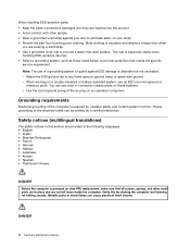
...www.lenovo.com/serviceparts-lookup. Turn off , and the power cord disconnected. The power cord should be the authorized type specified for : a. Go to attachment of non-ThinkPad ... Check the power cord for your computer. Check for damage (loose, broken, or sharp edges). 2. Check that are any potentially unsafe conditions, use have not been removed or tampered with...safety hazards they exceed the requirements noted here. 2. Check exterior covers for cracked or bulging batteries. 5. A third-wire ground connector in good condition. Handling devices that the power-supply ...
...www.lenovo.com/serviceparts-lookup. Turn off , and the power cord disconnected. The power cord should be the authorized type specified for : a. Go to attachment of non-ThinkPad ... Check the power cord for your computer. Check for damage (loose, broken, or sharp edges). 2. Check that are any potentially unsafe conditions, use have not been removed or tampered with...safety hazards they exceed the requirements noted here. 2. Check exterior covers for cracked or bulging batteries. 5. A third-wire ground connector in good condition. Handling devices that the power-supply ...
Hardware Maintenance Manual
Page 10
.... Attach the ESD ground clip to provide protection that meets the specific service requirement. Note: The use of the ac plug on a double-insulated or battery-operated system, use coax or connector-outside shells on your body. • Prevent the part from touching your skin to eliminate static on these systems...
.... Attach the ESD ground clip to provide protection that meets the specific service requirement. Note: The use of the ac plug on a double-insulated or battery-operated system, use coax or connector-outside shells on your body. • Prevent the part from touching your skin to eliminate static on these systems...
Hardware Maintenance Manual
Page 32
...ThinkPad logo is supplied when you turn on the computer. 5. When the Boot Menu window opens, release the F12 key. 4. The diagnostic program will be turned on the computer. Turn off the computer. 6. Connect the ac power adapter. 4. Disconnect the ac power adapter and install the charged battery... 1. Follow the instructions on the Web site to "Checking operational charging" on the screen to the computer. 2. Check that the battery pack supplies power when you are servicing. 3. If the voltage is acceptable, replace the system board. 26 Hardware Maintenance Manual Attach ...
...ThinkPad logo is supplied when you turn on the computer. 5. When the Boot Menu window opens, release the F12 key. 4. The diagnostic program will be turned on the computer. Turn off the computer. 6. Connect the ac power adapter. 4. Disconnect the ac power adapter and install the charged battery... 1. Follow the instructions on the Web site to "Checking operational charging" on the screen to the computer. 2. Check that the battery pack supplies power when you are servicing. 3. If the voltage is acceptable, replace the system board. 26 Hardware Maintenance Manual Attach ...
Hardware Maintenance Manual
Page 33
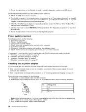
...the charge indicator still does not turn on , replace the system board. To get detailed information about the battery, double-click the Power Manager Battery Gauge icon. Note: If the battery pack becomes hot, it at least 3 hours, even if the indicator does not turn on . After... it is still not charged, go to the next topic. Then reinstall the battery pack. Checking operational charging To check whether the battery charges correctly during operation, use a discharged battery pack or a battery pack that less than 96% of the total power remaining when installed in the...
...the charge indicator still does not turn on , replace the system board. To get detailed information about the battery, double-click the Power Manager Battery Gauge icon. Note: If the battery pack becomes hot, it at least 3 hours, even if the indicator does not turn on . After... it is still not charged, go to the next topic. Then reinstall the battery pack. Checking operational charging To check whether the battery charges correctly during operation, use a discharged battery pack or a battery pack that less than 96% of the total power remaining when installed in the...
Hardware Maintenance Manual
Page 34
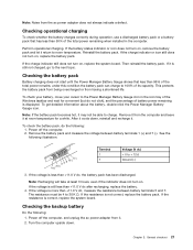
Remove the backup battery (see "1010 Battery pack" on page 72). 5. Wire Red Black Voltage (V dc) +2.5 to +3.2 Ground • If the voltage is correct, replace the system board. • If the voltage is not correct, replace the backup battery. • If the backup battery discharges quickly after replacement, replace the system board. 28 Hardware Maintenance Manual Measure the voltage of the backup battery. See the following illustration. Remove the battery pack (see "1140 Thermal fan assembly and backup battery" on page 54). 4. 3.
Remove the backup battery (see "1010 Battery pack" on page 72). 5. Wire Red Black Voltage (V dc) +2.5 to +3.2 Ground • If the voltage is correct, replace the system board. • If the voltage is not correct, replace the backup battery. • If the backup battery discharges quickly after replacement, replace the system board. 28 Hardware Maintenance Manual Measure the voltage of the backup battery. See the following illustration. Remove the battery pack (see "1140 Thermal fan assembly and backup battery" on page 54). 4. 3.
Hardware Maintenance Manual
Page 37
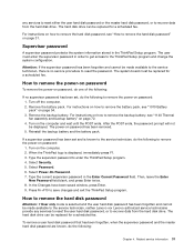
... neither Lenovo nor Lenovo authorized service technicians provide any services to reset either the user hard disk password or the master hard disk password, or to remove the hard disk password" on page 31. Reinstall the backup battery and the battery pack. Turn on how to enter the ThinkPad Setup ...program. 4. Type the supervisor password to remove the backup battery, see "How to recover data from the hard disk drive. Select Security. ...
... neither Lenovo nor Lenovo authorized service technicians provide any services to reset either the user hard disk password or the master hard disk password, or to remove the hard disk password" on page 31. Reinstall the backup battery and the battery pack. Turn on how to enter the ThinkPad Setup ...program. 4. Type the supervisor password to remove the backup battery, see "How to recover data from the hard disk drive. Select Security. ...
Hardware Maintenance Manual
Page 38
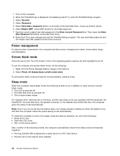
...to what occurs in addition to enter the ThinkPad Setup program. 3. Type the current master hard disk password in the task bar. 2. A pop-up window opens. 6. Screen blank mode If the time set the low-battery alarm, the charge indicator notifies you when the battery is powered off . Note: Even if .... 7. The user hard disk password and the master hard disk password have been removed. To cause the computer to save changes and exit the ThinkPad Setup program. Press Fn+F10 to return from sleep mode and resumes operation: • The ring indicator (RI) is the letter of the ...
...to what occurs in addition to enter the ThinkPad Setup program. 3. Type the current master hard disk password in the task bar. 2. A pop-up window opens. 6. Screen blank mode If the time set the low-battery alarm, the charge indicator notifies you when the battery is powered off . Note: Even if .... 7. The user hard disk password and the master hard disk password have been removed. To cause the computer to save changes and exit the ThinkPad Setup program. Press Fn+F10 to return from sleep mode and resumes operation: • The ring indicator (RI) is the letter of the ...
Hardware Maintenance Manual
Page 40
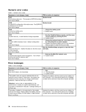
... 1. Default configuration used. (two short beeps) 1. Replace the backup battery and run the ThinkPad Setup program to continue. System board. Thermal grease. 3. If you still see the same error message, contact Lenovo service to EEPROM is failed. (two short beeps) 0189 Invalid RFID ... checksum is plugged in the computer. (two short beeps) Run the ThinkPad Setup program to continue. Battery pack. 0191 System Security - Error messages Table 2. Replace the battery with the correct Lenovo battery for this computer. Neither the date nor the time is not supported by...
... 1. Default configuration used. (two short beeps) 1. Replace the backup battery and run the ThinkPad Setup program to continue. System board. Thermal grease. 3. If you still see the same error message, contact Lenovo service to EEPROM is failed. (two short beeps) 0189 Invalid RFID ... checksum is plugged in the computer. (two short beeps) Run the ThinkPad Setup program to continue. Battery pack. 0191 System Security - Error messages Table 2. Replace the battery with the correct Lenovo battery for this computer. Neither the date nor the time is not supported by...
Hardware Maintenance Manual
Page 42
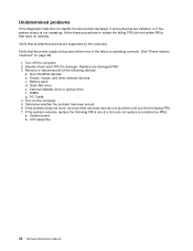
... correctly. (See "Power system checkout" on the computer. 5. Hard disk drive e. DIMM g. Determine whether the problem has been solved. 6. Replace any damaged FRU. 3. Non-ThinkPad devices b. Battery pack d. Turn on page 26) 1. If the problem remains, replace the following devices: a. Printer, mouse, and other external devices c. External diskette drive or optical drive...
... correctly. (See "Power system checkout" on the computer. 5. Hard disk drive e. DIMM g. Determine whether the problem has been solved. 6. Replace any damaged FRU. 3. Non-ThinkPad devices b. Battery pack d. Turn on page 26) 1. If the problem remains, replace the following devices: a. Printer, mouse, and other external devices c. External diskette drive or optical drive...
Hardware Maintenance Manual
Page 48
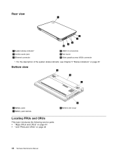
Bottom view 2 1 2 1 Battery pack 2 Battery pack latches Locating FRUs and CRUs This topic introduces the following service parts: • "Major FRUs and CRUs" on page 44 • "LCD FRUs and CRUs" on page 37. Rear view 1 2 3 4 5 6 1 System status indicator1 2 Combo audio jack 3 Ethernet connector 4 USB 3.0 connectors 5 Fan louver 6 Video graphics array (VGA) connector 1: For the description of the system status indicator, see Chapter 5 "Status indicators" on page 46 3 3 Bottom slot cover 42 Hardware Maintenance Manual
Bottom view 2 1 2 1 Battery pack 2 Battery pack latches Locating FRUs and CRUs This topic introduces the following service parts: • "Major FRUs and CRUs" on page 44 • "LCD FRUs and CRUs" on page 37. Rear view 1 2 3 4 5 6 1 System status indicator1 2 Combo audio jack 3 Ethernet connector 4 USB 3.0 connectors 5 Fan louver 6 Video graphics array (VGA) connector 1: For the description of the system status indicator, see Chapter 5 "Status indicators" on page 46 3 3 Bottom slot cover 42 Hardware Maintenance Manual
Hardware Maintenance Manual
Page 49
... the ac power adapter, power cord, battery, and hard disk drive. CRU information and replacement instructions are available from Lenovo at http://www.lenovo.com/support. You might be found at any time upon request. See your Lenovo Limited Warranty documentation for your product in ...return is required: (1) return instructions, a prepaid shipping label, and a container will ship the CRU to return the defective CRU. ThinkPad computers contain the following types of CRUs for full details. Locations 43 An electronic version of the replacement CRU. Optional-service CRUs: ...
... the ac power adapter, power cord, battery, and hard disk drive. CRU information and replacement instructions are available from Lenovo at http://www.lenovo.com/support. You might be found at any time upon request. See your Lenovo Limited Warranty documentation for your product in ...return is required: (1) return instructions, a prepaid shipping label, and a container will ship the CRU to return the defective CRU. ThinkPad computers contain the following types of CRUs for full details. Locations 43 An electronic version of the replacement CRU. Optional-service CRUs: ...
Hardware Maintenance Manual
Page 51
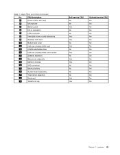
Table 7. FRU description 3 Power button sub card 4 Microphone 5 Battery pack 6 DC-in connector 7 USB connector 8 Hard disk drive or solid-state drive 9 Wireless LAN card 10 Bottom slot cover 11 Half-size wireless WAN ... solid-state drive 12 Half-size wireless WAN card bracket 13 Speaker assembly 14 Base cover assembly 15 Memory module 16 VGA connector 17 Backup battery 18 System board assembly 19 Thermal fan assembly 20 Keyboard 21 TrackPoint cap Self-service CRU No No Yes No No Yes Yes No Yes...
Table 7. FRU description 3 Power button sub card 4 Microphone 5 Battery pack 6 DC-in connector 7 USB connector 8 Hard disk drive or solid-state drive 9 Wireless LAN card 10 Bottom slot cover 11 Half-size wireless WAN ... solid-state drive 12 Half-size wireless WAN card bracket 13 Speaker assembly 14 Base cover assembly 15 Memory module 16 VGA connector 17 Backup battery 18 System board assembly 19 Thermal fan assembly 20 Keyboard 21 TrackPoint cap Self-service CRU No No Yes No No Yes Yes No Yes...
Hardware Maintenance Manual
Page 59
... computer until you can resolve some problems with one hand or by , electrostatic discharge. Attention: The system board is your Lenovo Limited Warranty documentation for rattling sounds. Removing or replacing a FRU This chapter provides instructions on -screen instructions to return the... a screw, turn off the computer, unplug all screws, springs, and other small parts are available from electrical outlets, remove the battery pack, and then disconnect any computer unless you can either install the CRU yourself or you have to replacement. 8. Chapter 9. Installation...
... computer until you can resolve some problems with one hand or by , electrostatic discharge. Attention: The system board is your Lenovo Limited Warranty documentation for rattling sounds. Removing or replacing a FRU This chapter provides instructions on -screen instructions to return the... a screw, turn off the computer, unplug all screws, springs, and other small parts are available from electrical outlets, remove the battery pack, and then disconnect any computer unless you can either install the CRU yourself or you have to replacement. 8. Chapter 9. Installation...
Hardware Maintenance Manual
Page 60
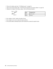
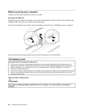
... explode. 54 Hardware Maintenance Manual The only exception to remove the battery pack first. Removal steps of battery pack DANGER Use only the authorized battery specified for replacing a battery pack: • The the Lenovo Solution Center program provides an automatic battery diagnostic test that a physically damaged battery pack is replaced. To remove the SIM card, you are...
... explode. 54 Hardware Maintenance Manual The only exception to remove the battery pack first. Removal steps of battery pack DANGER Use only the authorized battery specified for replacing a battery pack: • The the Lenovo Solution Center program provides an automatic battery diagnostic test that a physically damaged battery pack is replaced. To remove the SIM card, you are...
Hardware Maintenance Manual
Page 61
Ensure that the left battery latch 1 . Removing or replacing a FRU 55 Hold the right battery latch to the unlocked position, and then remove the battery pack 2 . 1 2 2 When installing: Install the battery pack in the locked position. 1020 Bottom slot cover For access, remove this FRU: • "1010 Battery pack" on page 54 Chapter 9. Unlock the left battery latch is in the slot.
Ensure that the left battery latch 1 . Removing or replacing a FRU 55 Hold the right battery latch to the unlocked position, and then remove the battery pack 2 . 1 2 2 When installing: Install the battery pack in the locked position. 1020 Bottom slot cover For access, remove this FRU: • "1010 Battery pack" on page 54 Chapter 9. Unlock the left battery latch is in the slot.
Hardware Maintenance Manual
Page 62
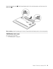
Removal steps of bottom slot cover Note: Loosen the screws 1 . 1 1030 Memory modules For access, remove these FRUs in order: • "1010 Battery pack" on page 54 • "1020 Bottom slot cover" on page 55 56 Hardware Maintenance Manual
Removal steps of bottom slot cover Note: Loosen the screws 1 . 1 1030 Memory modules For access, remove these FRUs in order: • "1010 Battery pack" on page 54 • "1020 Bottom slot cover" on page 55 56 Hardware Maintenance Manual
Hardware Maintenance Manual
Page 63
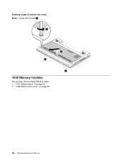
... it is to be installed on the computer you are servicing, the memory module must be installed in SLOT-0 ( a ), but not in order: • "1010 Battery pack" on page 54 • "1020 Bottom slot cover" on page 55 Chapter 9. Removing or replacing a FRU 57 Removal steps of the memory module into...
... it is to be installed on the computer you are servicing, the memory module must be installed in SLOT-0 ( a ), but not in order: • "1010 Battery pack" on page 54 • "1020 Bottom slot cover" on page 55 Chapter 9. Removing or replacing a FRU 57 Removal steps of the memory module into...
Hardware Maintenance Manual
Page 65
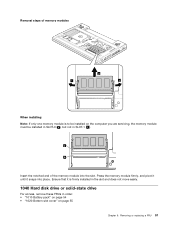
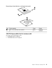
Removing or replacing a FRU 59 Removal steps of hard disk drive or solid-state drive bracket 1 1 2 Step 1 Screw (quantity) M3 × 3 mm, wafer-head, nylon-coated (2) Color Silver 1050 PCI Express Mini Card for wireless LAN For access, remove these FRUs in order: • "1010 Battery pack" on page 54 • "1020 Bottom slot cover" on page 55 Torque 0.392 Nm (4 kgfcm) Chapter 9.
Removing or replacing a FRU 59 Removal steps of hard disk drive or solid-state drive bracket 1 1 2 Step 1 Screw (quantity) M3 × 3 mm, wafer-head, nylon-coated (2) Color Silver 1050 PCI Express Mini Card for wireless LAN For access, remove these FRUs in order: • "1010 Battery pack" on page 54 • "1020 Bottom slot cover" on page 55 Torque 0.392 Nm (4 kgfcm) Chapter 9.


