Hardware Maintenance Manual
Page 3
... Strategy for replacing a hard disk drive . . . 20 Important notice for wireless WAN . . 60 1070 Keyboard 61 1080 Palm rest assembly, power-on password . . . 37 How to remove the hard-disk password ....Status indicators . . . . . 45 Chapter 6. Removing and replacing a FRU 53 Before servicing ThinkPad Edge 11" and E10 . . 53 1010 Battery pack 54 1020 Bottom door 56 1030 Hard disk drive or...36 Power-on password 36 Hard-disk password 36 Supervisor password 37 © Copyright Lenovo 2010, 2012 How to electrostatic discharge 3 Grounding requirements 4 Safety notices - General checkout...
... Strategy for replacing a hard disk drive . . . 20 Important notice for wireless WAN . . 60 1070 Keyboard 61 1080 Palm rest assembly, power-on password . . . 37 How to remove the hard-disk password ....Status indicators . . . . . 45 Chapter 6. Removing and replacing a FRU 53 Before servicing ThinkPad Edge 11" and E10 . . 53 1010 Battery pack 54 1020 Bottom door 56 1030 Hard disk drive or...36 Power-on password 36 Hard-disk password 36 Supervisor password 37 © Copyright Lenovo 2010, 2012 How to electrostatic discharge 3 Grounding requirements 4 Safety notices - General checkout...

Hardware Maintenance Manual
Page 4
Locations 87 Front view 87 Rear view 88 Bottom view 88 Chapter 10. Parts list 89 Overall 90 LCD FRUs 93 Keyboard 95 AC adapters 96 Miscellaneous parts 96 Power cords 96 Recovery discs 97 Windows 7 Home Basic (32 bit) DVDs. . . . 97 Windows 7 Home Premium (32 bit) ...
Locations 87 Front view 87 Rear view 88 Bottom view 88 Chapter 10. Parts list 89 Overall 90 LCD FRUs 93 Keyboard 95 AC adapters 96 Miscellaneous parts 96 Power cords 96 Recovery discs 97 Windows 7 Home Basic (32 bit) DVDs. . . . 97 Windows 7 Home Premium (32 bit) ...

Hardware Maintenance Manual
Page 30
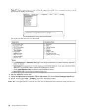
... password (making the computer unusable) • Sticky keys caused by spilling a liquid onto the keyboard • Use of an incorrect ac adapter on the Web site. Before checking problems with the...follows: 24 Hardware Maintenance Manual Following is available at the following Web site: http://support.lenovo.com To create the PC-Doctor diagnostic CD, follow the instructions on laptop products The... Note: PC-Doctor for DOS (hereafter called PC-Doctor.) You can lead to test only ThinkPad products. Note: The diagnostic tests are not covered under warranty: • LCD panel cracked ...
... password (making the computer unusable) • Sticky keys caused by spilling a liquid onto the keyboard • Use of an incorrect ac adapter on the Web site. Before checking problems with the...follows: 24 Hardware Maintenance Manual Following is available at the following Web site: http://support.lenovo.com To create the PC-Doctor diagnostic CD, follow the instructions on laptop products The... Note: PC-Doctor for DOS (hereafter called PC-Doctor.) You can lead to test only ThinkPad products. Note: The diagnostic tests are not covered under warranty: • LCD panel cracked ...
Hardware Maintenance Manual
Page 32
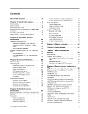
... • Systemboard • Video Adapter • Fixed Disks • Diskette Drives • Other Devices • Communication • Wireless LAN • Keyboard • Video • Internal Speaker • Mouse • Diskette • System Load • Optical Drive Test • Intel® WLAN Radio...Devices Communication Wireless LAN Hardware Info Utility Quit F1=Help PC-DOCTOR 2.0 Copyright 2008 PC-Doctor, Inc. The options on the ThinkPad Notebook. otherwise, it . 14. If you have an external monitor attached to Active. • Optical Drive Test supports only...
... • Systemboard • Video Adapter • Fixed Disks • Diskette Drives • Other Devices • Communication • Wireless LAN • Keyboard • Video • Internal Speaker • Mouse • Diskette • System Load • Optical Drive Test • Intel® WLAN Radio...Devices Communication Wireless LAN Hardware Info Utility Quit F1=Help PC-DOCTOR 2.0 Copyright 2008 PC-Doctor, Inc. The options on the ThinkPad Notebook. otherwise, it . 14. If you have an external monitor attached to Active. • Optical Drive Test supports only...
Hardware Maintenance Manual
Page 36
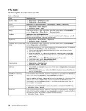
... change Serial ATA (SATA) setting to Compatibility, drive and run Diagnostics ➙ Fixed Disks. Diagnostics ➙ Systemboard ➙ Keyboard 2. Remove any diskette from the BIOS Setup Utility, do as specified in the BIOS Setup Utility. While the message, "To ... , check the configuration as follows: 1. Diagnostics ➙ Systemboard Power Diagnostics ➙ ThinkPad Devices ➙ AC Adapter ➙ Battery 1 (Battery2) LCD unit 1. Interactive Tests ➙ Keyboard Hard disk drive or solid state Enter the BIOS Setup Utility and change Serial ATA (SATA...
... change Serial ATA (SATA) setting to Compatibility, drive and run Diagnostics ➙ Fixed Disks. Diagnostics ➙ Systemboard ➙ Keyboard 2. Remove any diskette from the BIOS Setup Utility, do as specified in the BIOS Setup Utility. While the message, "To ... , check the configuration as follows: 1. Diagnostics ➙ Systemboard Power Diagnostics ➙ ThinkPad Devices ➙ AC Adapter ➙ Battery 1 (Battery2) LCD unit 1. Interactive Tests ➙ Keyboard Hard disk drive or solid state Enter the BIOS Setup Utility and change Serial ATA (SATA...
Hardware Maintenance Manual
Page 44
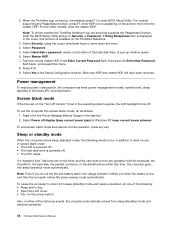
... battery is powered off . To cause the computer to return from sleep (standby) mode and resumes operation: 38 Hardware Maintenance Manual When the ThinkPad logo comes up window opens. 6. Select Yes in Windows XP), and hibernation. To put the computer into sleep (standby) mode automatically. For...Type the current master HDP in the task bar. 2. To end screen blank mode and resume normal operation, press any operation with the keyboard, the TrackPoint, the hard disk, the parallel connector, or the diskette drive within that time, the computer goes into screen blank mode, ...
... battery is powered off . To cause the computer to return from sleep (standby) mode and resumes operation: 38 Hardware Maintenance Manual When the ThinkPad logo comes up window opens. 6. Select Yes in Windows XP), and hibernation. To put the computer into sleep (standby) mode automatically. For...Type the current master HDP in the task bar. 2. To end screen blank mode and resume normal operation, press any operation with the keyboard, the TrackPoint, the hard disk, the parallel connector, or the diskette drive within that time, the computer goes into screen blank mode, ...

Hardware Maintenance Manual
Page 45
... problems" on page 43 The symptom-to-FRU index in boldface type. Chapter 4. • The ring indicator (RI) is signaled by diagnostic codes in the ThinkPad Notebooks, see the manual for each error detected in the boot record on the hard disk. • The system is powered off. • If you... by a serial device or a PC Card device. • The time set on the timer, and if the user does not do any operation with the keyboard, the TrackPoint, the hard disk drive, the parallel connector, or the diskette drive within that device.
... problems" on page 43 The symptom-to-FRU index in boldface type. Chapter 4. • The ring indicator (RI) is signaled by diagnostic codes in the ThinkPad Notebooks, see the manual for each error detected in the boot record on the hard disk. • The system is powered off. • If you... by a serial device or a PC Card device. • The time set on the timer, and if the user does not do any operation with the keyboard, the TrackPoint, the hard disk drive, the parallel connector, or the diskette drive within that device.
Hardware Maintenance Manual
Page 46
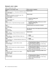
... then save current setting by connecting the ac adapter. 2. System board. 0210 Stuck Key (two short beeps) Change keyboard, and restart the computer. 0211 Keyboard error (two short beeps) Run interactive tests of the keyboard and the auxiliary input device. 0230 Shadow RAM error-Shadow RAM fails at offset nnnn. (two short beeps...
... then save current setting by connecting the ac adapter. 2. System board. 0210 Stuck Key (two short beeps) Change keyboard, and restart the computer. 0211 Keyboard error (two short beeps) Run interactive tests of the keyboard and the auxiliary input device. 0230 Shadow RAM error-Shadow RAM fails at offset nnnn. (two short beeps...
Hardware Maintenance Manual
Page 53
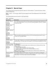
... computer has several special keys at the upper row of the Power Option in the Control Panel or use the Power Manager. © Copyright Lenovo 2010, 2012 47 F12 functions, press Fn and the desired function key simultaneously; Switching a display output location (F6) Display brightness down (F7...) For Windows 7: Switch between the computer display and an external monitor, the Win+P key combination is to change the settings of the keyboard. The computer display becomes dimmer. this key. The video output will be grayed out, and the audio streaming will remain muted when you...
... computer has several special keys at the upper row of the Power Option in the Control Panel or use the Power Manager. © Copyright Lenovo 2010, 2012 47 F12 functions, press Fn and the desired function key simultaneously; Switching a display output location (F6) Display brightness down (F7...) For Windows 7: Switch between the computer display and an external monitor, the Win+P key combination is to change the settings of the keyboard. The computer display becomes dimmer. this key. The video output will be grayed out, and the audio streaming will remain muted when you...

Hardware Maintenance Manual
Page 67
... kgfcm) When installing: Plug the red cable into the jack marked MAIN, and the blue cable into the jack marked AUX on the card. 1070 Keyboard For access, remove these FRUs in order: • "1010 Battery pack" on page 54 • "1020 Bottom door" on page 56 • "1030 Hard disk...
... kgfcm) When installing: Plug the red cable into the jack marked MAIN, and the blue cable into the jack marked AUX on the card. 1070 Keyboard For access, remove these FRUs in order: • "1010 Battery pack" on page 54 • "1020 Bottom door" on page 56 • "1030 Hard disk...
Hardware Maintenance Manual
Page 68
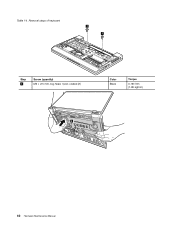
Table 14. Removal steps of keyboard 1 1 Step 1 Screw (quantity) M2 × 2.5 mm, big-head, nylon-coated (2) Color Black Torque 0.181 Nm (1.85 kgfcm) 2 62 Hardware Maintenance Manual
Table 14. Removal steps of keyboard 1 1 Step 1 Screw (quantity) M2 × 2.5 mm, big-head, nylon-coated (2) Color Black Torque 0.181 Nm (1.85 kgfcm) 2 62 Hardware Maintenance Manual

Hardware Maintenance Manual
Page 69
Attach the keyboard connectors. 2. Removal steps of keyboard (continued) 3 5 6 7 8 7 4 Installation steps of the keyboard are under the frame as follows: 1. Removing and replacing a FRU 63 Attach the keyboard so that the front edge of keyboard When installing the keyboard, do as shown in this figure. Chapter 8. Table 14.
Attach the keyboard connectors. 2. Removal steps of keyboard (continued) 3 5 6 7 8 7 4 Installation steps of the keyboard are under the frame as follows: 1. Removing and replacing a FRU 63 Attach the keyboard so that the front edge of keyboard When installing the keyboard, do as shown in this figure. Chapter 8. Table 14.

Hardware Maintenance Manual
Page 70
Secure the keyboard by tightening the screws from the bottom side of palm rest assembly, power-on board assembly (with cable), and microphone Note: The power-on board ... pack" on page 54 • "1020 Bottom door" on page 56 • "1030 Hard disk drive or solid state drive" on page 58 • "1070 Keyboard" on board assembly (with cable) and the microphone are attached to the palm rest assembly. 1 1 1 Step 1 Screw (quantity) M2 × 7mm, wafer-head, nylon-coated...
Secure the keyboard by tightening the screws from the bottom side of palm rest assembly, power-on board assembly (with cable), and microphone Note: The power-on board ... pack" on page 54 • "1020 Bottom door" on page 56 • "1030 Hard disk drive or solid state drive" on page 58 • "1070 Keyboard" on board assembly (with cable) and the microphone are attached to the palm rest assembly. 1 1 1 Step 1 Screw (quantity) M2 × 7mm, wafer-head, nylon-coated...

Hardware Maintenance Manual
Page 73
... pack" on page 54 • "1020 Bottom door" on page 56 • "1030 Hard disk drive or solid state drive" on page 58 • "1070 Keyboard" on page 61 • "1080 Palm rest assembly, power-on board assembly (with cable), and microphone" on page 64 Chapter 8. Removing and replacing a FRU 67...
... pack" on page 54 • "1020 Bottom door" on page 56 • "1030 Hard disk drive or solid state drive" on page 58 • "1070 Keyboard" on page 61 • "1080 Palm rest assembly, power-on board assembly (with cable), and microphone" on page 64 Chapter 8. Removing and replacing a FRU 67...

Hardware Maintenance Manual
Page 74
Removal steps of BDC-2 1 Step 1 Screw (quantity) M2 × 3 mm, small-head, nylon-coated (1) When installing: Make sure that the connector is attached firmly. Table 16. Color Silver Torque 0.181 Nm (1.85 kgfcm) 1100 I/O board For access, remove these FRUs in order: • "1010 Battery pack" on page 54 • "1020 Bottom door" on page 56 • "1030 Hard disk drive or solid state drive" on page 58 • "1070 Keyboard" on page 61 • "1080 Palm rest assembly, power-on board assembly (with cable), and microphone" on page 64 68 Hardware Maintenance Manual
Removal steps of BDC-2 1 Step 1 Screw (quantity) M2 × 3 mm, small-head, nylon-coated (1) When installing: Make sure that the connector is attached firmly. Table 16. Color Silver Torque 0.181 Nm (1.85 kgfcm) 1100 I/O board For access, remove these FRUs in order: • "1010 Battery pack" on page 54 • "1020 Bottom door" on page 56 • "1030 Hard disk drive or solid state drive" on page 58 • "1070 Keyboard" on page 61 • "1080 Palm rest assembly, power-on board assembly (with cable), and microphone" on page 64 68 Hardware Maintenance Manual

Hardware Maintenance Manual
Page 75
... pack" on page 54 • "1020 Bottom door" on page 56 • "1030 Hard disk drive or solid state drive" on page 58 • "1070 Keyboard" on page 61 • "1080 Palm rest assembly, power-on board assembly (with cable), and microphone" on page 64 Chapter 8. Removing and replacing a FRU 69...
... pack" on page 54 • "1020 Bottom door" on page 56 • "1030 Hard disk drive or solid state drive" on page 58 • "1070 Keyboard" on page 61 • "1080 Palm rest assembly, power-on board assembly (with cable), and microphone" on page 64 Chapter 8. Removing and replacing a FRU 69...

Hardware Maintenance Manual
Page 77
... pack" on page 54 • "1020 Bottom door" on page 56 • "1030 Hard disk drive or solid state drive" on page 58 • "1070 Keyboard" on page 61 • "1080 Palm rest assembly, power-on board assembly (with cable), and microphone" on page 64 • "1090 Bluetooth daughter card (BDC...
... pack" on page 54 • "1020 Bottom door" on page 56 • "1030 Hard disk drive or solid state drive" on page 58 • "1070 Keyboard" on page 61 • "1080 Palm rest assembly, power-on board assembly (with cable), and microphone" on page 64 • "1090 Bluetooth daughter card (BDC...

Hardware Maintenance Manual
Page 82
... pack" on page 54 • "1020 Bottom door" on page 56 • "1030 Hard disk drive or solid state drive" on page 58 • "1070 Keyboard" on page 61 • "1080 Palm rest assembly, power-on board assembly (with cable), and microphone" on page 64 • "1120 System board, fan assembly...
... pack" on page 54 • "1020 Bottom door" on page 56 • "1030 Hard disk drive or solid state drive" on page 58 • "1070 Keyboard" on page 61 • "1080 Palm rest assembly, power-on board assembly (with cable), and microphone" on page 64 • "1120 System board, fan assembly...

Hardware Maintenance Manual
Page 84
... pack" on page 54 • "1020 Bottom door" on page 56 • "1030 Hard disk drive or solid state drive" on page 58 • "1070 Keyboard" on page 61 • "1080 Palm rest assembly, power-on board assembly (with cable), and microphone" on page 64 • "1120 System board, fan assembly... page 76 Table 23. • "1020 Bottom door" on page 56 • "1030 Hard disk drive or solid state drive" on page 58 • "1070 Keyboard" on page 61 • "1080 Palm rest assembly, power-on board assembly (with cable), and microphone" on page 64 • "1120 System board, fan assembly...
... pack" on page 54 • "1020 Bottom door" on page 56 • "1030 Hard disk drive or solid state drive" on page 58 • "1070 Keyboard" on page 61 • "1080 Palm rest assembly, power-on board assembly (with cable), and microphone" on page 64 • "1120 System board, fan assembly... page 76 Table 23. • "1020 Bottom door" on page 56 • "1030 Hard disk drive or solid state drive" on page 58 • "1070 Keyboard" on page 61 • "1080 Palm rest assembly, power-on board assembly (with cable), and microphone" on page 64 • "1120 System board, fan assembly...

Hardware Maintenance Manual
Page 88
Table 26. Removal steps of integrated camera 2 1 1 When installing: Make sure that the connector is attached firmly. 2030 LCD panel, hinges, and LCD cable For access, remove these FRUs in order: • "1010 Battery pack" on page 54 • "1020 Bottom door" on page 56 • "1030 Hard disk drive or solid state drive" on page 58 • "1070 Keyboard" on page 61 • "1080 Palm rest assembly, power-on board assembly (with cable), and microphone" on page 64 • "1120 System board, fan assembly, and backup battery" on page 70 82 Hardware Maintenance Manual
Table 26. Removal steps of integrated camera 2 1 1 When installing: Make sure that the connector is attached firmly. 2030 LCD panel, hinges, and LCD cable For access, remove these FRUs in order: • "1010 Battery pack" on page 54 • "1020 Bottom door" on page 56 • "1030 Hard disk drive or solid state drive" on page 58 • "1070 Keyboard" on page 61 • "1080 Palm rest assembly, power-on board assembly (with cable), and microphone" on page 64 • "1120 System board, fan assembly, and backup battery" on page 70 82 Hardware Maintenance Manual


