(English) Rescue and Recovery 4.3 Deployment Guide
Page 5
... . . . 20 Sysprep Backup/Restore 21 Mapping a network drive for backups . . . . 22 Password Persistence 25 EFS file limitation 25 Battery power settings for CD or script files 57 Scenario 5 - Notices 85 Trademarks 86 © Copyright Lenovo 2008, 2009 iii Contents Preface v Chapter 1. Best practices 51 Scenario 1 - New rollouts 51 Preparing the hard disk drive 51 Installing 51 Updating 53 Enabling the Rescue and Recovery desktop . . . 53 Scenario 2 - Administrative...
... . . . 20 Sysprep Backup/Restore 21 Mapping a network drive for backups . . . . 22 Password Persistence 25 EFS file limitation 25 Battery power settings for CD or script files 57 Scenario 5 - Notices 85 Trademarks 86 © Copyright Lenovo 2008, 2009 iii Contents Preface v Chapter 1. Best practices 51 Scenario 1 - New rollouts 51 Preparing the hard disk drive 51 Installing 51 Updating 53 Enabling the Rescue and Recovery desktop . . . 53 Scenario 2 - Administrative...
(English) Rescue and Recovery 4.3 Deployment Guide
Page 30
... is created on the registry settings located at HKLM\Software\Lenovo\MND. Capturing a Sysprep utility image in the rnrdeploy.xml file. To silently install the setup files using the MSIEXE file: a. To complete a merge operation, MOVE permissions exist for backups The mapping network drive function relies on the network share, the service makes the directory a read-only folder, and assigns it access rights so that only...
... is created on the registry settings located at HKLM\Software\Lenovo\MND. Capturing a Sysprep utility image in the rnrdeploy.xml file. To silently install the setup files using the MSIEXE file: a. To complete a merge operation, MOVE permissions exist for backups The mapping network drive function relies on the network share, the service makes the directory a read-only folder, and assigns it access rights so that only...
(English) Rescue and Recovery 4.3 Deployment Guide
Page 36
... directed to use the e-mail function integrated in a location which can be displayed each time the Rescue and Recovery program starts. The Diagnostics tool available in the Predesktop Area of this external file will be restored. The administrator can disable the simplified user interface at : HKLM\SOFTWARE\Lenovo\Rescue and Recovery\Settings\ExcludeList. Rescue and Recovery interface switching The Rescue and Recovery user interface provides the option to e-mail...
... directed to use the e-mail function integrated in a location which can be displayed each time the Rescue and Recovery program starts. The Diagnostics tool available in the Predesktop Area of this external file will be restored. The administrator can disable the simplified user interface at : HKLM\SOFTWARE\Lenovo\Rescue and Recovery\Settings\ExcludeList. Rescue and Recovery interface switching The Rescue and Recovery user interface provides the option to e-mail...
(English) Rescue and Recovery 4.5 Deployment Guide
Page 26
... Complete will appear. 6. To install the setup files using the power button. 8. Capture the image for deployment. ="C:\TVTRR" REBOOT="R"" /w 2. Capturing a multiple partition machine and excluding files in a Sysprep backup To capture multiple partitions in C:\tvtrr\Program Files\Lenovo\Rescue and Recovery: To EXCLUDE a partition, add the following command: : Perform the install of the Rescue and Recovery program. The status bar with a reboot : Type the following command on one...
... Complete will appear. 6. To install the setup files using the power button. 8. Capture the image for deployment. ="C:\TVTRR" REBOOT="R"" /w 2. Capturing a multiple partition machine and excluding files in a Sysprep backup To capture multiple partitions in C:\tvtrr\Program Files\Lenovo\Rescue and Recovery: To EXCLUDE a partition, add the following command: : Perform the install of the Rescue and Recovery program. The status bar with a reboot : Type the following command on one...

(English) Rescue and Recovery 4.5 Deployment Guide
Page 27
... and Recovery program using the power button. 10. If you must set the registry entry to use Password Persistence. Capture the image for deployment. To silently install the setup files using the MSI with a reboot : Type the following command on one line cd "\Program Files\Lenovo\Rescue and Recovery" rrcmd sysprepbackup location=L name="Sysprep Base Backup" If you wish to backup to a partition other than the Windows main operating...
... and Recovery program using the power button. 10. If you must set the registry entry to use Password Persistence. Capture the image for deployment. To silently install the setup files using the MSI with a reboot : Type the following command on one line cd "\Program Files\Lenovo\Rescue and Recovery" rrcmd sysprepbackup location=L name="Sysprep Base Backup" If you wish to backup to a partition other than the Windows main operating...
(English) Rescue and Recovery 4.5 Deployment Guide
Page 51
... A "\". New rollouts This section describes installing the Rescue and Recovery program in the process is the extraction of S drive" on the primary hard disk drive. 1. In order to install Windows on each machine by roughly one storage device attached). After running, you are going to make sure you will find the following command: CLEANDRV /HDD=0 4. SET SOURCEDRIVE=C: :: Create the RRTemp directory on it. 3. Manually creating the Service Partition...
... A "\". New rollouts This section describes installing the Rescue and Recovery program in the process is the extraction of S drive" on the primary hard disk drive. 1. In order to install Windows on each machine by roughly one storage device attached). After running, you are going to make sure you will find the following command: CLEANDRV /HDD=0 4. SET SOURCEDRIVE=C: :: Create the RRTemp directory on it. 3. Manually creating the Service Partition...
(English) Rescue and Recovery 4.5 Deployment Guide
Page 67
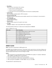
... version of the machine: - 0 - After running this tool, the applications that the service partition was set to prior to booting to alternate operating system; This program can be useless. Run before installing the Rescue and Recovery program. 3. DOS for the boot manager to user if proper BIOS calls not supported. The following table provides error codes and error descriptions for Windows. 4. CleanMBR cleans the Master Boot Record. Use the cleanmbr.exe...
... version of the machine: - 0 - After running this tool, the applications that the service partition was set to prior to booting to alternate operating system; This program can be useless. Run before installing the Rescue and Recovery program. 3. DOS for the boot manager to user if proper BIOS calls not supported. The following table provides error codes and error descriptions for Windows. 4. CleanMBR cleans the Master Boot Record. Use the cleanmbr.exe...

Hardware Maintenance Manual for ThinkCentre M90z
Page 39
... problem: 1. Set all external devices. 2. Power-on the computer. • Look for displayed error codes • Listen for beep codes • Look for readable instructions or a main menu on all cables and power cords. 3. If you did not receive the correct response, proceed to step 7 on page 35. • If you receive an error, replace the part that software package. Is the failure repeatable? © Copyright Lenovo 2010, 2012 33 Run...
... problem: 1. Set all external devices. 2. Power-on the computer. • Look for displayed error codes • Listen for beep codes • Look for readable instructions or a main menu on all cables and power cords. 3. If you did not receive the correct response, proceed to step 7 on page 35. • If you receive an error, replace the part that software package. Is the failure repeatable? © Copyright Lenovo 2010, 2012 33 Run...

Hardware Maintenance Manual for ThinkCentre M90z
Page 47
... disable user access to enable or disable a USB connector. USB Support SATA Controller Use this option is set to Disabled, the device connected to the SATA connector (such as a hard disk drive or the disc in this section to press Esc several times. 5. To enable or disable a device, do the following : • From the Setup Utility program main menu, select Devices ® USB Setup and follow the instructions on how to save the new settings and exit the Setup Utility program. Selecting a startup device If your computer does not start...
... disable user access to enable or disable a USB connector. USB Support SATA Controller Use this option is set to Disabled, the device connected to the SATA connector (such as a hard disk drive or the disc in this section to press Esc several times. 5. To enable or disable a device, do the following : • From the Setup Utility program main menu, select Devices ® USB Setup and follow the instructions on how to save the new settings and exit the Setup Utility program. Selecting a startup device If your computer does not start...
Hardware Maintenance Manual for ThinkCentre M90z
Page 68
... screen the next time you have bootable media. 62 ThinkCentre Hardware Maintenance Manual Checksum of CMOS is correctly installed. To purposely configure the computer without a keyboard, set to the computer and that check the operation of the system and some basic system-board operations • Checks the memory operation • Starts the video operation • Verifies that CMOS has become corrupt due to a weak CMOS battery. This information gives specifics about the type and location...
... screen the next time you have bootable media. 62 ThinkCentre Hardware Maintenance Manual Checksum of CMOS is correctly installed. To purposely configure the computer without a keyboard, set to the computer and that check the operation of the system and some basic system-board operations • Checks the memory operation • Starts the video operation • Verifies that CMOS has become corrupt due to a weak CMOS battery. This information gives specifics about the type and location...

Hardware Maintenance Manual for ThinkCentre M90z
Page 69
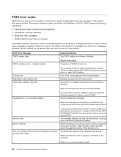
...) 1. Power Switch 2. Ensure that network is enabled in -use light remains on page 39) 4. Diskette Drive 2. System Board 3. System Board 2. Memory Module 3. Riser card, if installed. Network adapter (advise network administrator of characters and color bars 1. Hard Disk Drive Cable Incorrect memory size during POST 1. System Board "Insert a Diskette" icon appears with a known-good diagnostics diskette in startup sequence as first device or first device after diskette. 2. Ensure that the operating system settings are set to right of new...
...) 1. Power Switch 2. Ensure that network is enabled in -use light remains on page 39) 4. Diskette Drive 2. System Board 3. System Board 2. Memory Module 3. Riser card, if installed. Network adapter (advise network administrator of characters and color bars 1. Hard Disk Drive Cable Incorrect memory size during POST 1. System Board "Insert a Diskette" icon appears with a known-good diagnostics diskette in startup sequence as first device or first device after diskette. 2. Ensure that the operating system settings are set to right of new...

Hardware Maintenance Manual for ThinkCentre M90z
Page 280
... can download a self-starting bootable disc image (known as the first boot device. On the Startup Device Menu, select the desired optical drive as an ISO image) with the system program updates to download, extract, and install the update. However, if you press N. Updating (flashing) the BIOS from your machine type: a. To update (flash) the BIOS from your operating system Note: Because Lenovo makes constant improvements to its Web sites, the Web page contents are connected to change the serial number...
... can download a self-starting bootable disc image (known as the first boot device. On the Startup Device Menu, select the desired optical drive as an ISO image) with the system program updates to download, extract, and install the update. However, if you press N. Updating (flashing) the BIOS from your machine type: a. To update (flash) the BIOS from your operating system Note: Because Lenovo makes constant improvements to its Web sites, the Web page contents are connected to change the serial number...
(English) User Guide
Page 5
... recovery operation 57 Using the Rescue and Recovery workspace . . . 57 Creating and using a rescue medium 58 Creating a rescue medium 58 Using a rescue medium 59 Installing or reinstalling device drivers . . . . . 59 Solving recovery problems 60 Chapter 4. Using the Setup Utility program 61 Starting the Setup Utility program 61 Viewing or changing settings 61 Using passwords 61 Password considerations 62 Administrator password 62 Power-on password 62 Hard disk drive password 62 Setting, changing, or deleting a password . . 62 Enabling or disabling a device 63 Selecting a startup...
... recovery operation 57 Using the Rescue and Recovery workspace . . . 57 Creating and using a rescue medium 58 Creating a rescue medium 58 Using a rescue medium 59 Installing or reinstalling device drivers . . . . . 59 Solving recovery problems 60 Chapter 4. Using the Setup Utility program 61 Starting the Setup Utility program 61 Viewing or changing settings 61 Using passwords 61 Password considerations 62 Administrator password 62 Power-on password 62 Hard disk drive password 62 Setting, changing, or deleting a password . . 62 Enabling or disabling a device 63 Selecting a startup...

(English) User Guide
Page 10
...) and SM software • Wake on page 9. Connectivity • 10/100/1000 Mbps Ethernet controller System management features • Ability to store the power-on self-test (POST) hardware test results • Advanced Configuration and Power Interface (ACPI) support • Automatic power-on startup • Desktop Management Interface (DMI) • Intel Active Management Technology (AMT) (available in some models) • Enabling or disabling SATA devices • Enabling or disabling the serial port • Enabling or disabling USB connectors individually 2 ThinkCentre User Guide
...) and SM software • Wake on page 9. Connectivity • 10/100/1000 Mbps Ethernet controller System management features • Ability to store the power-on self-test (POST) hardware test results • Advanced Configuration and Power Interface (ACPI) support • Automatic power-on startup • Desktop Management Interface (DMI) • Intel Active Management Technology (AMT) (available in some models) • Enabling or disabling SATA devices • Enabling or disabling the serial port • Enabling or disabling USB connectors individually 2 ThinkCentre User Guide
(English) User Guide
Page 20
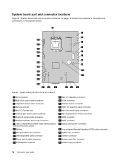
... 4 Memory slots (2) 5 Mini PCI Express slot 6 Ambient light sensor cable connector 7 Bluetooth module cable connector 8 Wireless keyboard and mouse connector 9 Clear Complementary Metal Oxide Semiconductor (CMOS) /Recovery jumper 10 Battery 11 Microprocessor fan connector 12 Internal speaker cable connector 13 Power switch cable connector 14 ExpressCard connector 15 Rear I/O assembly connector 16 COM connector 17 Thermal sensor connector 18 Right I/O assembly cable connector 19 Hard disk drive power connector 20 PS/2 keyboard and mouse connector 21 SATA connector 22 SATA connector 23 Optical...
... 4 Memory slots (2) 5 Mini PCI Express slot 6 Ambient light sensor cable connector 7 Bluetooth module cable connector 8 Wireless keyboard and mouse connector 9 Clear Complementary Metal Oxide Semiconductor (CMOS) /Recovery jumper 10 Battery 11 Microprocessor fan connector 12 Internal speaker cable connector 13 Power switch cable connector 14 ExpressCard connector 15 Rear I/O assembly connector 16 COM connector 17 Thermal sensor connector 18 Right I/O assembly cable connector 19 Hard disk drive power connector 20 PS/2 keyboard and mouse connector 21 SATA connector 22 SATA connector 23 Optical...

(English) User Guide
Page 28
... : http://www.lenovo.com/support This section provides instructions on page 12. 12. Your computer has two slots for installing or replacing DDR3 SODIMMs (small outline dual inline memory modules). Figure 11. Reinstall the four screws to secure the VESA frame to the system board. Reconnect the thermal sensor cable to the computer main bracket. 11. See "System board part and connector locations" on...
... : http://www.lenovo.com/support This section provides instructions on page 12. 12. Your computer has two slots for installing or replacing DDR3 SODIMMs (small outline dual inline memory modules). Figure 11. Reinstall the four screws to secure the VESA frame to the system board. Reconnect the thermal sensor cable to the computer main bracket. 11. See "System board part and connector locations" on...

(English) User Guide
Page 67
... USB connectors on the software media that you have created a rescue medium using the secondary internal hard disk drive, set the secondary internal hard disk drive as the first boot device in the startup device sequence to complete the recovery process. Using a rescue medium This section provides instructions on the Windows Vista operating system, do the following to use the rescue medium: 1. On the Startup Device Menu, select the desired optical drive as the first boot device and press Enter. The rescue medium starts...
... USB connectors on the software media that you have created a rescue medium using the secondary internal hard disk drive, set the secondary internal hard disk drive as the first boot device in the startup device sequence to complete the recovery process. Using a rescue medium This section provides instructions on the Windows Vista operating system, do the following to use the rescue medium: 1. On the Startup Device Menu, select the desired optical drive as the first boot device and press Enter. The rescue medium starts...
(English) User Guide
Page 68
... device (an internal hard disk drive, a disc, a USB hard disk drive, or other methods of your computer, such as WIN98.txt. Solving recovery problems If you are unable to the factory default settings. See "Creating and using a rescue medium" on the screen to install the device driver. Use Windows Explorer or My Computer to the C:\SWTOOLS directory. 4. See "Selecting a startup device" on page 61. It is set as the first boot device in the startup device sequence in your hard disk drive...
... device (an internal hard disk drive, a disc, a USB hard disk drive, or other methods of your computer, such as WIN98.txt. Solving recovery problems If you are unable to the factory default settings. See "Creating and using a rescue medium" on the screen to install the device driver. Use Windows Explorer or My Computer to the C:\SWTOOLS directory. 4. See "Selecting a startup device" on page 61. It is set as the first boot device in the startup device sequence in your hard disk drive...

(English) User Guide
Page 71
... accessed. When this option is disabled and cannot be used. Start the Setup Utility program. Notes: a. If you want to the SATA connector (such as expected, do not want to return to select the desired startup device. Press F10 to enable or disable a USB connector. When the Startup Device Menu opens, release the F12 key. 3. USB Support SATA Controller Use this section to begin. You can use the instructions in an optical drive) as the hard disk drive or the optical drive) is set to Disabled...
... accessed. When this option is disabled and cannot be used. Start the Setup Utility program. Notes: a. If you want to the SATA connector (such as expected, do not want to return to select the desired startup device. Press F10 to enable or disable a USB connector. When the Startup Device Menu opens, release the F12 key. 3. USB Support SATA Controller Use this section to begin. You can use the instructions in an optical drive) as the hard disk drive or the optical drive) is set to Disabled...
(English) User Guide
Page 94
... specifications 4 power supply features 2 power supply, replacing 45 Power-on password 62 power-on self-test (POST) 65 programs, updating system 65 protection, password 52 purchasing additional services 76 R rear I/O assembly, replacing 43 recovering a POST/BIOS update failure 66 86 ThinkCentre User Guide software 55 recovery boot-block 66 operations, backup and 56 problems, solving 60 recovery media, creating and using 55 reinstalling device drivers 59 removing computer cover 14 replacing ambient light sensor 36 battery 22 Bluetooth module 33 card reader 42 ExpressCard 37 hard disk drive...
... specifications 4 power supply features 2 power supply, replacing 45 Power-on password 62 power-on self-test (POST) 65 programs, updating system 65 protection, password 52 purchasing additional services 76 R rear I/O assembly, replacing 43 recovering a POST/BIOS update failure 66 86 ThinkCentre User Guide software 55 recovery boot-block 66 operations, backup and 56 problems, solving 60 recovery media, creating and using 55 reinstalling device drivers 59 removing computer cover 14 replacing ambient light sensor 36 battery 22 Bluetooth module 33 card reader 42 ExpressCard 37 hard disk drive...


