User Manual
Page 5
...hard disk drive 14 Replacing the optical drive 16 Replacing the battery 17 Replacing the heat sink 18 Replacing the internal speaker 19 Replacing the front audio and USB assembly 20 Replacing the ac power adapter 21 Replacing the ac power adapter bracket. . . 22 Replacing the keyboard or mouse . . . . . 25 Completing the parts replacement . . . . . 25 Installing security features 26 Integrated cable lock 26 Password protection 27 Erasing lost or forgotten passwords (clearing CMOS 27 Chapter 3. Recovery information. . . 29 Creating and using recovery media 29 Creating recovery media...
...hard disk drive 14 Replacing the optical drive 16 Replacing the battery 17 Replacing the heat sink 18 Replacing the internal speaker 19 Replacing the front audio and USB assembly 20 Replacing the ac power adapter 21 Replacing the ac power adapter bracket. . . 22 Replacing the keyboard or mouse . . . . . 25 Completing the parts replacement . . . . . 25 Installing security features 26 Integrated cable lock 26 Password protection 27 Erasing lost or forgotten passwords (clearing CMOS 27 Chapter 3. Recovery information. . . 29 Creating and using recovery media 29 Creating recovery media...

User Manual
Page 9
... specific model, use the Setup Utility program. See Chapter 4 "Using the Setup Utility program" on some models) System management features • Ability to two double data rate 3 small outline dual inline memory modules (DDR3 SODIMMs) Internal drives • Optical drive • Serial Advanced Technology Attachment (SATA) hard disk drive (available in some models) Video subsystem • Integrated graphics card for a Video Graphics Array (VGA) connector and a DisplayPort connector Audio subsystem • Integrated high-definition (HD) audio • Audio line-in connector, audio...
... specific model, use the Setup Utility program. See Chapter 4 "Using the Setup Utility program" on some models) System management features • Ability to two double data rate 3 small outline dual inline memory modules (DDR3 SODIMMs) Internal drives • Optical drive • Serial Advanced Technology Attachment (SATA) hard disk drive (available in some models) Video subsystem • Integrated graphics card for a Video Graphics Array (VGA) connector and a DisplayPort connector Audio subsystem • Integrated high-definition (HD) audio • Audio line-in connector, audio...

User Manual
Page 10
... optical drive bay • One PCI card slot Power Supply • 130-watt power adapter • Advanced Configuration and Power Interface (ACPI) support Security features • Computrace • Cover presence switch (also called intrusion switch) • Enabling or disabling a device • Enabling or disabling USB connectors individually • Hard disk drive password • Keyboard with fingerprint reader (shipped with some models) • System Management (SM) Basic Input/Output System (BIOS) and SM software • Wake on LAN • Wake on Ring • Windows Management...
... optical drive bay • One PCI card slot Power Supply • 130-watt power adapter • Advanced Configuration and Power Interface (ACPI) support Security features • Computrace • Cover presence switch (also called intrusion switch) • Enabling or disabling a device • Enabling or disabling USB connectors individually • Hard disk drive password • Keyboard with fingerprint reader (shipped with some models) • System Management (SM) Basic Input/Output System (BIOS) and SM software • Wake on LAN • Wake on Ring • Windows Management...

User Manual
Page 29
...://www.lenovo.com/support This section provides instructions on page 9. 12. Install the new power switch assembly into the chassis and align the screw hole in the front audio and USB assembly with the corresponding hole in the ThinkCentre Safety and Warranty Guide that secures the front audio and USB assembly to the system board. Connect the front USB, front panel, and front audio cables to the chassis. Locate the power switch...
...://www.lenovo.com/support This section provides instructions on page 9. 12. Install the new power switch assembly into the chassis and align the screw hole in the front audio and USB assembly with the corresponding hole in the ThinkCentre Safety and Warranty Guide that secures the front audio and USB assembly to the system board. Connect the front USB, front panel, and front audio cables to the chassis. Locate the power switch...

User Manual
Page 34
... the device-driver files. Installation instructions are provided in . Note: Make sure that are several security options available to help you prevent hardware theft and unauthorized access to the computer. Installing security features There are not preinstalled at : http://www.lenovo.com/support 26 ThinkCentre User Guide In addition to open the computer cover. Cable routing 4. Figure 24. Close the computer cover as the Kensington lock, can be used...
... the device-driver files. Installation instructions are provided in . Note: Make sure that are several security options available to help you prevent hardware theft and unauthorized access to the computer. Installing security features There are not preinstalled at : http://www.lenovo.com/support 26 ThinkCentre User Guide In addition to open the computer cover. Cable routing 4. Figure 24. Close the computer cover as the Kensington lock, can be used...
User Manual
Page 42
... or permanently changing the startup device sequence. The TXT file contains information about the Setup Utility program, see Chapter 4 "Using the Setup Utility program" on page 32. • Use recovery media if all other external devices) set of recovery media as early as AUDIO or VIDEO. 5. Use Windows Explorer or My Computer to display the directory structure of recovery have the rescue device (an internal hard disk drive, a disc, a USB hard disk drive, or other methods of your Windows Help and Support information system...
... or permanently changing the startup device sequence. The TXT file contains information about the Setup Utility program, see Chapter 4 "Using the Setup Utility program" on page 32. • Use recovery media if all other external devices) set of recovery media as early as AUDIO or VIDEO. 5. Use Windows Explorer or My Computer to display the directory structure of recovery have the rescue device (an internal hard disk drive, a disc, a USB hard disk drive, or other methods of your Windows Help and Support information system...

User Manual
Page 59
... software 6 audio line-in connector 7 audio line-out connector 7 audio subsystem 1 B backup and recovery operations 30 basic troubleshooting 41 battery, replacing 17 boot-block recovery 40 C cable lock, security 26 cables, connecting 25 changing password 36 startup device sequence 37 cleaning an optical mouse 44 CMOS, clearing 27 components, internal 8 computer cover opening 12 connector description 7 connectors front 6 rear 7 considerations, passwords 35 creating and using a rescue medium 32 creating and using recovery media 29 CRU completing the installation 25 customer support center...
... software 6 audio line-in connector 7 audio line-out connector 7 audio subsystem 1 B backup and recovery operations 30 basic troubleshooting 41 battery, replacing 17 boot-block recovery 40 C cable lock, security 26 cables, connecting 25 changing password 36 startup device sequence 37 cleaning an optical mouse 44 CMOS, clearing 27 components, internal 8 computer cover opening 12 connector description 7 connectors front 6 rear 7 considerations, passwords 35 creating and using a rescue medium 32 creating and using recovery media 29 CRU completing the installation 25 customer support center...
User Manual
Page 60
... for Rescue and Recovery 43 physical specifications 3 power Advanced Configuration and Power Interface (ACPI) support 2 features 2 power-on self-test (POST) 39 Power-On, Password 36 productivity center, ThinkVantage 45 programs, updating system 39 protection, password 27 purchasing additional services 48 R rear connectors 7 52 ThinkCentre User Guide recovering from a POST/BIOS update failure 40 software 29 recovery boot-block 40 operations, backup and 30 problems, solving 34 recovery media, creating and using 29 reinstalling device drivers 33 replacing battery 17 hard disk drive 14 heat sink...
... for Rescue and Recovery 43 physical specifications 3 power Advanced Configuration and Power Interface (ACPI) support 2 features 2 power-on self-test (POST) 39 Power-On, Password 36 productivity center, ThinkVantage 45 programs, updating system 39 protection, password 27 purchasing additional services 48 R rear connectors 7 52 ThinkCentre User Guide recovering from a POST/BIOS update failure 40 software 29 recovery boot-block 40 operations, backup and 30 problems, solving 34 recovery media, creating and using 29 reinstalling device drivers 33 replacing battery 17 hard disk drive 14 heat sink...
BIOS Windows Management Instrumentation Interface Deployment Guide
Page 19
... item is Disabled or with special setting, this item will be hidden and can only be updated or cleared. ·When user try to change these settings, you must reboot the system after changing one of them. ·A password cannot be set using this method when one power cycle. Please reference Table 4 for BIOS setup: ·Administrator password, POP,HDP and the item"Hardware Password Manager" cannot be updated through...
... item is Disabled or with special setting, this item will be hidden and can only be updated or cleared. ·When user try to change these settings, you must reboot the system after changing one of them. ·A password cannot be set using this method when one power cycle. Please reference Table 4 for BIOS setup: ·Administrator password, POP,HDP and the item"Hardware Password Manager" cannot be updated through...

Hardware Maintenance Manual
Page 41
... cables and power cords. 3. General checkout Attention The drives in and then a black screen displays, contact your operating system is not logged on page 391. Verify that the latest level of the system board. If you are servicing might have an internal hard disk drive and use a remote hard disk drive accessed through the Secure Managed Client - Storage Array (SMC - Before replacing a FRU, ensure that the user name is stored. Check all external devices...
... cables and power cords. 3. General checkout Attention The drives in and then a black screen displays, contact your operating system is not logged on page 391. Verify that the latest level of the system board. If you are servicing might have an internal hard disk drive and use a remote hard disk drive accessed through the Secure Managed Client - Storage Array (SMC - Before replacing a FRU, ensure that the user name is stored. Check all external devices...

Hardware Maintenance Manual
Page 50
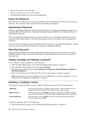
... the Setup Utility program main menu, select Security. 3. Depending on how to enable or disable user access to the following devices: USB Setup SATA Controller External SATA Port Use this option to enable or disable a USB connector. Enabling or disabling a device This section provides information on the password type, select Set Power-On Password, Set Administrator Password, or Hard Disk Password. 4. Start the Setup Utility program. The computer cannot be used . When an Administrator Password is set an Administrator Password. Start the Setup Utility program. Follow the instructions on...
... the Setup Utility program main menu, select Security. 3. Depending on how to enable or disable user access to the following devices: USB Setup SATA Controller External SATA Port Use this option to enable or disable a USB connector. Enabling or disabling a device This section provides information on the password type, select Set Power-On Password, Set Administrator Password, or Hard Disk Password. 4. Start the Setup Utility program. The computer cannot be used . When an Administrator Password is set an Administrator Password. Start the Setup Utility program. Follow the instructions on...

Hardware Maintenance Manual
Page 71
... to enable Wake on page 41) 4. System Board Diskette drive in startup sequence as first device or first device after the POST is enabled in Setup/Configuration (see "Starting the Setup Utility program" on LAN. 3. Ensure that network is attached. Press any key to network adapter. 2. This error occurs only after diskette 2. Riser card, if installed Computer will not power-off and remove all of the fingerprint keyboards except the one external fingerprint reader is in -use light...
... to enable Wake on page 41) 4. System Board Diskette drive in startup sequence as first device or first device after the POST is enabled in Setup/Configuration (see "Starting the Setup Utility program" on LAN. 3. Ensure that network is attached. Press any key to network adapter. 2. This error occurs only after diskette 2. Riser card, if installed Computer will not power-off and remove all of the fingerprint keyboards except the one external fingerprint reader is in -use light...

Hardware Maintenance Manual
Page 399
...-server remote location while offering users the flexibility and performance of a traditional desktop computer. Use the following : • Passwords • Vital Product Data • Secure Managed Client (some models) Hardware-controlled passwords Use the Setup Utility program to obtain the latest level of BIOS. • To determine the current level of BIOS can cause false errors and unnecessary FRU replacement. Storage Array, contact the network or storage administrator. Lenovo Customer Support Center ©...
...-server remote location while offering users the flexibility and performance of a traditional desktop computer. Use the following : • Passwords • Vital Product Data • Secure Managed Client (some models) Hardware-controlled passwords Use the Setup Utility program to obtain the latest level of BIOS. • To determine the current level of BIOS can cause false errors and unnecessary FRU replacement. Storage Array, contact the network or storage administrator. Lenovo Customer Support Center ©...

Hardware Maintenance Manual
Page 405
... Password 42 setting, changing, deleting 42 passwords, using 41 PC-Doctor for Rescue and Recovery 36 PCI card 83, 108 installing, replacing 83, 108 slots 83 power supply assembly, replacing 74, 110 Power-On, Password 42 R rear fan assembly, replacing 93 recovering from a POST/BIOS update failure 392 recovery boot-block 392 removing computer cover 68 replacing battery 81, 105 hard disk drive 85, 118 heat sink 112 heat sink and fan assembly 75 S security enabling or disabling 42 selecting startup device 43 temporary startup device 43 setting password 42 settings changing...
... Password 42 setting, changing, deleting 42 passwords, using 41 PC-Doctor for Rescue and Recovery 36 PCI card 83, 108 installing, replacing 83, 108 slots 83 power supply assembly, replacing 74, 110 Power-On, Password 42 R rear fan assembly, replacing 93 recovering from a POST/BIOS update failure 392 recovery boot-block 392 removing computer cover 68 replacing battery 81, 105 hard disk drive 85, 118 heat sink 112 heat sink and fan assembly 75 S security enabling or disabling 42 selecting startup device 43 temporary startup device 43 setting password 42 settings changing...
Hardware Maintenance Manual
Page 48
... computer is turned on the password type, select Set Power-On Password, Set Administrator Password, or Hard Disk Password. 4. When this option is set , you are prompted to type a valid password each time you try to access the hard disk drive. When this option to the USB connector cannot be used until a valid password is typed in . When an Administrator Password is disabled, the device connected to enable or disable a USB connector. See "Starting the Setup Utility program" on page 41. 42 ThinkCentre Hardware Maintenance Manual See "Starting the Setup Utility program" on...
... computer is turned on the password type, select Set Power-On Password, Set Administrator Password, or Hard Disk Password. 4. When this option is set , you are prompted to type a valid password each time you try to access the hard disk drive. When this option to the USB connector cannot be used until a valid password is typed in . When an Administrator Password is disabled, the device connected to enable or disable a USB connector. See "Starting the Setup Utility program" on page 41. 42 ThinkCentre Hardware Maintenance Manual See "Starting the Setup Utility program" on...
Hardware Maintenance Manual
Page 59
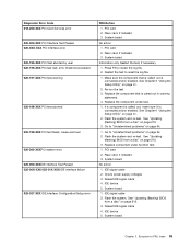
... interface Configuration/Setup error FRU/Action 1. PCI card 2. Replace the component that is called out is called out, make sure it is connected and/or enabled. See Chapter 6 "Using the Setup Utility" on page 64. 2. Go to -FRU index 53 Replace component under test. 1. IDE device 5. IDE signal cable 2. PCI card 2. Check power supply voltages 3. Riser card, if installed 3. Press F3 to reset the log file. 1. Replace the component under function test. 1. See "Updating (flashing) BIOS from a disc" on...
... interface Configuration/Setup error FRU/Action 1. PCI card 2. Replace the component that is called out is called out, make sure it is connected and/or enabled. See Chapter 6 "Using the Setup Utility" on page 64. 2. Go to -FRU index 53 Replace component under test. 1. IDE device 5. IDE signal cable 2. PCI card 2. Check power supply voltages 3. Riser card, if installed 3. Press F3 to reset the log file. 1. Replace the component under function test. 1. See "Updating (flashing) BIOS from a disc" on...

Hardware Maintenance Manual
Page 60
... cable 4. Restart the test to "Undetermined problems" on page 64. 1. Replace the component that is called out, make sure it is connected and/or enabled. If a component is called out is connected and/or enabled. Go to reset the log file. 1. SCSI adapter card, if installed 5. SCSI device 4. System board Information only Restart the test, if necessary. 54 ThinkCentre Hardware Maintenance Manual See Chapter 6 "Using the Setup Utility" on page 210 3. See "Updating (flashing) BIOS from a disc...
... cable 4. Restart the test to "Undetermined problems" on page 64. 1. Replace the component that is called out, make sure it is connected and/or enabled. If a component is called out is connected and/or enabled. Go to reset the log file. 1. SCSI adapter card, if installed 5. SCSI device 4. System board Information only Restart the test, if necessary. 54 ThinkCentre Hardware Maintenance Manual See Chapter 6 "Using the Setup Utility" on page 210 3. See "Updating (flashing) BIOS from a disc...

Hardware Maintenance Manual
Page 69
... set to enable Wake on LAN. 3. This error occurs only after diskette 2. Power Switch 2. Ensure network administrator is completed. Network adapter (advise network administrator of new MAC address) Computer will not PXE from server 1. System Board Diskette drive in-use light remains on or does not light when drive is in Setup/Configuration (see "Starting the Setup Utility program" on LAN® (if applicable) 1. System Board 2. Primary Hard Disk Drive 3. No operating system found. See "Power problems" on page 31. 1. Riser card, if installed...
... set to enable Wake on LAN. 3. This error occurs only after diskette 2. Power Switch 2. Ensure network administrator is completed. Network adapter (advise network administrator of new MAC address) Computer will not PXE from server 1. System Board Diskette drive in-use light remains on or does not light when drive is in Setup/Configuration (see "Starting the Setup Utility program" on LAN® (if applicable) 1. System Board 2. Primary Hard Disk Drive 3. No operating system found. See "Power problems" on page 31. 1. Riser card, if installed...

Hardware Maintenance Manual
Page 81
.... Go to "Completing the parts replacement" on how to the chassis. Open the computer cover. Install the screw to secure the new front audio and USB assembly to the system board. Install the new power switch assembly into the chassis and align the screw hole in the chassis. 9. Connect the front USB, front panel, and front audio cables to the chassis. 10. Chapter 8. Turn off the computer and disconnect...
.... Go to "Completing the parts replacement" on how to the chassis. Open the computer cover. Install the screw to secure the new front audio and USB assembly to the system board. Install the new power switch assembly into the chassis and align the screw hole in the chassis. 9. Connect the front USB, front panel, and front audio cables to the chassis. 10. Chapter 8. Turn off the computer and disconnect...

Hardware Maintenance Manual
Page 221
...) 210 boot-block recovery 210 C cables, connecting 89 changing password 42 startup device sequence 43 components, internal 68 computer cover opening 71 connectors front 67 rear 67 considerations, passwords 41 CRU completing the installation 89 D deleting a password 42 E environment, operating 30 exiting, Setup Utility 43 F failure, recovering from POST/BIOS 210 flashing BIOS 210 front audio and USB assembly, replacing 74 front connectors 67 H hard disk drive, replacing 82 heat sink, replacing 75 I installing options memory module 72 internal speaker, replacing 88 © Copyright Lenovo 2010...
...) 210 boot-block recovery 210 C cables, connecting 89 changing password 42 startup device sequence 43 components, internal 68 computer cover opening 71 connectors front 67 rear 67 considerations, passwords 41 CRU completing the installation 89 D deleting a password 42 E environment, operating 30 exiting, Setup Utility 43 F failure, recovering from POST/BIOS 210 flashing BIOS 210 front audio and USB assembly, replacing 74 front connectors 67 H hard disk drive, replacing 82 heat sink, replacing 75 I installing options memory module 72 internal speaker, replacing 88 © Copyright Lenovo 2010...


