
User Manual
Page 5
... and recovery operations . . . 42 Using the Rescue and Recovery workspace . . . . 43 Creating and using rescue media 44 Creating and using a Recovery Repair diskette . . 45 Recovering or installing device drivers . . . . . 46 Setting a rescue device in bay 3. . . . . . 34 Installing security features 35 Integrated cable lock 36 Padlock 37 Password protection 37 Changing the battery 37 Erasing a lost or forgotten password (clearing CMOS 38 Replacing the cover and connecting the cables. . . 39 Chapter 4. Updating system programs 53 Using system programs 53 Updating (flashing) BIOS...
... and recovery operations . . . 42 Using the Rescue and Recovery workspace . . . . 43 Creating and using rescue media 44 Creating and using a Recovery Repair diskette . . 45 Recovering or installing device drivers . . . . . 46 Setting a rescue device in bay 3. . . . . . 34 Installing security features 35 Integrated cable lock 36 Padlock 37 Password protection 37 Changing the battery 37 Erasing a lost or forgotten password (clearing CMOS 38 Replacing the cover and connecting the cables. . . 39 Chapter 4. Updating system programs 53 Using system programs 53 Updating (flashing) BIOS...
User Manual
Page 15
... instructions. Power supply statement Never remove the cover on a power supply or any component that has the following label attached. Users and installers in North America. Do not remove the drive covers. There are present inside any part that has this label attached. Danger Laser radiation when open. Laser compliance statement Some personal computer models are also sold separately as options. CD and DVD drives are equipped from the factory...
... instructions. Power supply statement Never remove the cover on a power supply or any component that has the following label attached. Users and installers in North America. Do not remove the drive covers. There are present inside any part that has this label attached. Danger Laser radiation when open. Laser compliance statement Some personal computer models are also sold separately as options. CD and DVD drives are equipped from the factory...
User Manual
Page 31
... Access Help online help system. If you need service or technical support, you install your operating system. Updates could include security fixes, new versions of Windows components (such as media player), fixes to install all device drivers after you will probably be asked for your hard disk with the device drivers. Installing other portions of antivirus software on how to open the online help system for more information about updating your antivirus software. Setting...
... Access Help online help system. If you need service or technical support, you install your operating system. Updates could include security fixes, new versions of Windows components (such as media player), fixes to install all device drivers after you will probably be asked for your hard disk with the device drivers. Installing other portions of antivirus software on how to open the online help system for more information about updating your antivirus software. Setting...

User Manual
Page 52
... the Customer Support Center. 32 User Guide Maximum height: 26.1 mm (1.0 in bay 3 (some models) Any bay that does not have a drive installed has a static shield and bay panel installed. Drive specifications Your computer comes with the following illustration shows the locations of drives you can obtain a Universal Adapter Bracket, 5.25 to 3.5-inch) * 5.25-inch hard disk drive 2 Bay 2 - The following factory-installed drives: v An optical drive in bay 1 (some models) v A 3.5-inch hard disk drive in...
... the Customer Support Center. 32 User Guide Maximum height: 26.1 mm (1.0 in bay 3 (some models) Any bay that does not have a drive installed has a static shield and bay panel installed. Drive specifications Your computer comes with the following illustration shows the locations of drives you can obtain a Universal Adapter Bracket, 5.25 to 3.5-inch) * 5.25-inch hard disk drive 2 Bay 2 - The following factory-installed drives: v An optical drive in bay 1 (some models) v A 3.5-inch hard disk drive in...
User Manual
Page 70
... can type either password. If you can also use your administrator password. If both the user and administrator passwords are set an Administrator Password. However, to Enable, all devices connected to access the Setup Utility program. Select Set Passwords. When this feature is set to Disable, all diskettes are treated as hard disk drives or the CD-ROM drive) are not case sensitive v Not be your name or your previous password User Password When a User Password is set, the user is...
... can type either password. If you can also use your administrator password. If both the user and administrator passwords are set an Administrator Password. However, to Enable, all devices connected to access the Setup Utility program. Select Set Passwords. When this feature is set to Disable, all diskettes are treated as hard disk drives or the CD-ROM drive) are not case sensitive v Not be your name or your previous password User Password When a User Password is set, the user is...
User Manual
Page 75
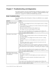
... . v The monitor power cord is turned on . If you cannot correct the problem, have the computer serviced. v The monitor is plugged into the monitor and into a working electrical outlet. Action Verify that it is securely connected to the correct setting for your computer" on . The monitor screen is turned on and the brightness and contrast controls are set to the keyboard connector on the computer. v The keyboard is switched on...
... . v The monitor power cord is turned on . If you cannot correct the problem, have the computer serviced. v The monitor is plugged into the monitor and into a working electrical outlet. Action Verify that it is securely connected to the correct setting for your computer" on . The monitor screen is turned on and the brightness and contrast controls are set to the keyboard connector on the computer. v The keyboard is switched on...
User Manual
Page 84
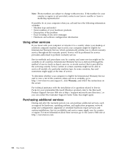
... site at http://www.lenovo.com. 64 User Guide Service availability and service name might not be at your computer when you call and have the following information available: v Machine type and model v Serial numbers of your preinstalled Microsoft Windows product, refer to the Microsoft Product Support Services Web site at the time of any error messages v Hardware and software configuration information Using other services If you can purchase...
... site at http://www.lenovo.com. 64 User Guide Service availability and service name might not be at your computer when you call and have the following information available: v Machine type and model v Serial numbers of your preinstalled Microsoft Windows product, refer to the Microsoft Product Support Services Web site at the time of any error messages v Hardware and software configuration information Using other services If you can purchase...
User Manual
Page 95
... B battery, changing 37 BIOS, updating (flashing) 53 C cables, connecting 39 changing startup device sequence 51 changing the battery 37 CMOS, clearing 38 components, internal 23 computer connecting 4 shutting down 11 turning on computer 10 connecting drives 33 connector description 21 connectors front 19 rear 20 cover removing 22 replacing 39 Customer Replacement Units (CRUs) 62 Customer Support Center 63 D device drivers 21 diagnostic CD image 10, 57, 58 diskettes 10, 57, 58, 59 PC-Doctor for DOS 56, 57 PC-Doctor for Windows...
... B battery, changing 37 BIOS, updating (flashing) 53 C cables, connecting 39 changing startup device sequence 51 changing the battery 37 CMOS, clearing 38 components, internal 23 computer connecting 4 shutting down 11 turning on computer 10 connecting drives 33 connector description 21 connectors front 19 rear 20 cover removing 22 replacing 39 Customer Replacement Units (CRUs) 62 Customer Support Center 63 D device drivers 21 diagnostic CD image 10, 57, 58 diskettes 10, 57, 58, 59 PC-Doctor for DOS 56, 57 PC-Doctor for Windows...
User Manual
Page 96
... and Recovery 41 S security features 15 padlock 37 selecting startup device 51 temporary startup device 51 serial connector 21 Setup Utility 49 software installing 10 system board components, accessing 24 connectors 26, 27 identifying parts 25 location 26, 27, 28 76 User Guide system board (continued) memory 16, 29 system management 14 system programs 53 T ThinkVantage Productivity Center 61 trademarks 74 troubleshooting 55 U updating (flashing) BIOS 53 antivirus software 11 operating system 11 updating system programs 53 USB connectors 21 using passwords 49...
... and Recovery 41 S security features 15 padlock 37 selecting startup device 51 temporary startup device 51 serial connector 21 Setup Utility 49 software installing 10 system board components, accessing 24 connectors 26, 27 identifying parts 25 location 26, 27, 28 76 User Guide system board (continued) memory 16, 29 system management 14 system programs 53 T ThinkVantage Productivity Center 61 trademarks 74 troubleshooting 55 U updating (flashing) BIOS 53 antivirus software 11 operating system 11 updating system programs 53 USB connectors 21 using passwords 49...
(English) Rescue and Recovery 4.3 Deployment Guide
Page 5
... and Recovery environmental variables . . 13 Compatibility with Active Directory and ADM files 57 Corporate Active Directory Rollout . . . . . 58 Scenario 6 - Standalone install for hard drive setup: Option 2 . . 55 Scenario 3 - Contents Preface v Chapter 1. Best practices 51 Scenario 1 - User tasks 83 Windows 7 83 Create rescue media 83 Rescue and Recovery user interface switching . . . 84 Appendix C. New rollouts 51 Preparing the hard disk drive 51 Installing 51 Updating 53 Enabling the Rescue and Recovery desktop...
... and Recovery environmental variables . . 13 Compatibility with Active Directory and ADM files 57 Corporate Active Directory Rollout . . . . . 58 Scenario 6 - Standalone install for hard drive setup: Option 2 . . 55 Scenario 3 - Contents Preface v Chapter 1. Best practices 51 Scenario 1 - User tasks 83 Windows 7 83 Create rescue media 83 Rescue and Recovery user interface switching . . . 84 Appendix C. New rollouts 51 Preparing the hard disk drive 51 Installing 51 Updating 53 Enabling the Rescue and Recovery desktop...
(English) Rescue and Recovery 4.3 Deployment Guide
Page 30
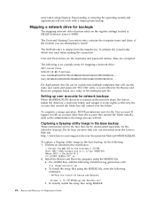
... the network share, the service makes the directory a read-only folder, and assigns it access rights so that only the account that will use the same user name and password. Setting up user accounts for mapping a network drive: UNC=\\server\share NetPath=\\9.88.77.66\share User=11622606415119207723014918505422010521006401209203708202015... Install the Rescue and Recovery program using Sysprep. The following installation-log generation code: /L*v %temp%\rrinstall.txt b. Capturing a Sysprep utility image in...
... the network share, the service makes the directory a read-only folder, and assigns it access rights so that only the account that will use the same user name and password. Setting up user accounts for mapping a network drive: UNC=\\server\share NetPath=\\9.88.77.66\share User=11622606415119207723014918505422010521006401209203708202015... Install the Rescue and Recovery program using Sysprep. The following installation-log generation code: /L*v %temp%\rrinstall.txt b. Capturing a Sysprep utility image in...
(English) Rescue and Recovery 4.3 Deployment Guide
Page 36
... and Recovery user interface provides the option to use the e-mail function integrated in problem determination. By default, you can disable the simplified user interface at : HKLM\SOFTWARE\Lenovo\Rescue and Recovery\Settings\ExcludeList. If the Simplified User Interface setting is no way to transmit information through the registry key settings: HKLM\SOFTWARE\Lenovo\Rescue and Recovery\Settings\OSAppsList The OSAppsList setting will define what files, folders, or file types comprise the operating...
... and Recovery user interface provides the option to use the e-mail function integrated in problem determination. By default, you can disable the simplified user interface at : HKLM\SOFTWARE\Lenovo\Rescue and Recovery\Settings\ExcludeList. If the Simplified User Interface setting is no way to transmit information through the registry key settings: HKLM\SOFTWARE\Lenovo\Rescue and Recovery\Settings\OSAppsList The OSAppsList setting will define what files, folders, or file types comprise the operating...
(English) Rescue and Recovery 4.5 Deployment Guide
Page 51
... Metal Restore from the target hard disk drive. 2. Boot the diskette (only one time will reduce the installation time on the HDD for your donor system. New rollouts" on Lenovo-branded computers. Install the operating system and applications. Installing This first step in a new rollout on page 45 • "Scenario 2 - SET SOURCEDRIVE=C: :: Create the RRTemp directory on each machine by roughly one-half. 1. New rollouts This...
... Metal Restore from the target hard disk drive. 2. Boot the diskette (only one time will reduce the installation time on the HDD for your donor system. New rollouts" on Lenovo-branded computers. Install the operating system and applications. Installing This first step in a new rollout on page 45 • "Scenario 2 - SET SOURCEDRIVE=C: :: Create the RRTemp directory on each machine by roughly one-half. 1. New rollouts This...

Hardware Maintenance Manual
Page 5
... Types 8013, 8716, 8976, 8986, 9266, 9282, 9374, 9384, and 9647 108 Replacing the hard disk drive 112 Replacing an optical drive 115 Replacing the diskette drive 117 Replacing the power switch/LED assembly . . . 119 Replacing the front panel card 121 Replacing the system fan assembly 122 Replacing a PCI adapter 124 Completing the FRU replacement 124 Chapter 9. Diagnostics 43 PC-Doctor for Windows 43 PC-Doctor for DOS 43 Creating a diagnostic CD image 44 Creating diagnostic diskettes 44 Running diagnostics...
... Types 8013, 8716, 8976, 8986, 9266, 9282, 9374, 9384, and 9647 108 Replacing the hard disk drive 112 Replacing an optical drive 115 Replacing the diskette drive 117 Replacing the power switch/LED assembly . . . 119 Replacing the front panel card 121 Replacing the system fan assembly 122 Replacing a PCI adapter 124 Completing the FRU replacement 124 Chapter 9. Diagnostics 43 PC-Doctor for Windows 43 PC-Doctor for DOS 43 Creating a diagnostic CD image 44 Creating diagnostic diskettes 44 Running diagnostics...
Hardware Maintenance Manual
Page 47
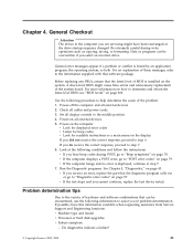
..." on the system. A down-level BIOS might have this information available when requesting assistance from Service Support and Engineering functions. Power-off the computer and all external devices. 5. Power-on page 43. Run the Diagnostic programs. See Chapter 5, "Diagnostics," on all external devices. 2. v Machine type and model v Processor or hard disk upgrades v Failure symptom - General error messages appear if a problem or conflict is installed on page 78. Before replacing any FRUs, ensure that the...
..." on the system. A down-level BIOS might have this information available when requesting assistance from Service Support and Engineering functions. Power-off the computer and all external devices. 5. Power-on page 43. Run the Diagnostic programs. See Chapter 5, "Diagnostics," on all external devices. 2. v Machine type and model v Processor or hard disk upgrades v Failure symptom - General error messages appear if a problem or conflict is installed on page 78. Before replacing any FRUs, ensure that the...
Hardware Maintenance Manual
Page 64
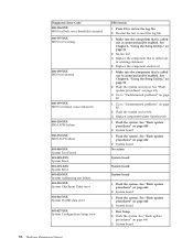
... Hardware Maintenance Manual Make sure the component that is connected and/or enabled. Flash the system. Run Setup 2. Flash the system and retest. System board 1. Replace the component under function test 1. Flash the system. Flash the system. See "Flash update procedures" on page 606 2. See Chapter 6, "Using the Setup Utility," on page 51 2. System board No action System board System board System board 1. Replace component under test 1. See Chapter 6, "Using the Setup Utility," on page 51 2. Diagnostic Error Code 000-196-XXX BIOS test...
... Hardware Maintenance Manual Make sure the component that is connected and/or enabled. Flash the system. Run Setup 2. Flash the system and retest. System board 1. Replace the component under function test 1. Flash the system. Flash the system. See "Flash update procedures" on page 606 2. See Chapter 6, "Using the Setup Utility," on page 51 2. System board No action System board System board System board 1. Replace component under test 1. See Chapter 6, "Using the Setup Utility," on page 51 2. Diagnostic Error Code 000-196-XXX BIOS test...
Hardware Maintenance Manual
Page 87
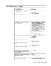
... operating system settings are set to network adapter 2. System Board Diskette drive in-use light remains on or does not light when drive is enabled in Setup/Configuration (see "Starting the Setup Utility program" on page 51) 4. System Board ″Insert a Diskette″ icon appears with an otherwise blank display. 1. System Board 2. System Board No power or fan not running 1. Check power supply and signal cable connections to enable Wake on page 55. Power Supply 2. Memory Module 3. Network Adapter Intensity or color varies from server 1. See "Power...
... operating system settings are set to network adapter 2. System Board Diskette drive in-use light remains on or does not light when drive is enabled in Setup/Configuration (see "Starting the Setup Utility program" on page 51) 4. System Board ″Insert a Diskette″ icon appears with an otherwise blank display. 1. System Board 2. System Board No power or fan not running 1. Check power supply and signal cable connections to enable Wake on page 55. Power Supply 2. Memory Module 3. Network Adapter Intensity or color varies from server 1. See "Power...
Hardware Maintenance Manual
Page 88
... not listed above (including blank or illegible display) 1. System Board Power-on indicator or hard disk drive in the first 3.5-inch diskette drive 1. Power switch/LED assembly light not on the keyboard do not work 1. System Board Printer problems 1. Run Setup and check Startup sequence. 2. Diskette Drive 3. Power Supply RPL computer cannot access programs from server 1. First device - Second device - Check startup sequence 2. Check the network adapter LED status Serial or parallel port device failure (system board port) 1. External Device 3. Cable 4. External...
... not listed above (including blank or illegible display) 1. System Board Power-on indicator or hard disk drive in the first 3.5-inch diskette drive 1. Power switch/LED assembly light not on the keyboard do not work 1. System Board Printer problems 1. Run Setup and check Startup sequence. 2. Diskette Drive 3. Power Supply RPL computer cannot access programs from server 1. First device - Second device - Check startup sequence 2. Check the network adapter LED status Serial or parallel port device failure (system board port) 1. External Device 3. Cable 4. External...
Hardware Maintenance Manual
Page 134
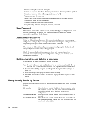
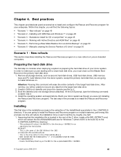
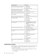
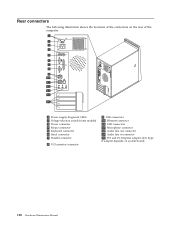
Rear connectors The following illustration shows the locations of the connectors on the rear of the computer. 1 Power supply diagnostic LEDs 2 Voltage selection switch (some models) 3 Power connector 4 Mouse connector 5 Keyboard connector 6 Serial connector 7 Parallel connector 8 VGA monitor connector 9 USB connectors 10 Ethernet connector 11 USB connectors 12 Microphone connector 13 Audio line out connector 14 Audio line in connector 15 PCI and PCI Express adapter slots (type of adapter depends on system board) 128 Hardware Maintenance Manual
Rear connectors The following illustration shows the locations of the connectors on the rear of the computer. 1 Power supply diagnostic LEDs 2 Voltage selection switch (some models) 3 Power connector 4 Mouse connector 5 Keyboard connector 6 Serial connector 7 Parallel connector 8 VGA monitor connector 9 USB connectors 10 Ethernet connector 11 USB connectors 12 Microphone connector 13 Audio line out connector 14 Audio line in connector 15 PCI and PCI Express adapter slots (type of adapter depends on system board) 128 Hardware Maintenance Manual

Hardware Maintenance Manual
Page 146
Go to the hard disk drive. 25. See "Removing the cover" on page 130. 26. Disconnect the signal and power cables from the failing system board and install them in the PCI connectors. 4. Carefully take note of the location of the chassis. 9. Remove the memory modules from the hard disk drive. 5. Install the new system board into position. 24. Connect the power and signal cables to "Completing the FRU replacement" on page 160. Types 8700, 8717...
Go to the hard disk drive. 25. See "Removing the cover" on page 130. 26. Disconnect the signal and power cables from the failing system board and install them in the PCI connectors. 4. Carefully take note of the location of the chassis. 9. Remove the memory modules from the hard disk drive. 5. Install the new system board into position. 24. Connect the power and signal cables to "Completing the FRU replacement" on page 160. Types 8700, 8717...


