(English) User Guide - Lenovo K450e
Page 39
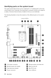
... the system board The system board (also known as the "mainboard" or "motherboard") is the main circuit board in your computer. The following illustration shows the locations of devices that are factory-installed or that you can install later. Lenovo K450e 12 3 4 5 6 7 8 9 10 11 12 13 27 26 25 24 23 22 21...
... the system board The system board (also known as the "mainboard" or "motherboard") is the main circuit board in your computer. The following illustration shows the locations of devices that are factory-installed or that you can install later. Lenovo K450e 12 3 4 5 6 7 8 9 10 11 12 13 27 26 25 24 23 22 21...
Lenovo K4 Series Hardware Maintenance Manual
Page 3
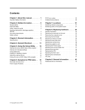
... devices 5 Grounding requirements 6 Safety notices 6 Chapter 3. General information . . . . . 9 Specifications 9 Chapter 4. Using the Setup Utility. . . 13 Starting the Lenovo BIOS Setup Utility program . 13 Viewing and changing settings 13 Using passwords 13 Enabling or disabling a device 15 Selecting a startup device 16 Exiting the...Replacing the microprocessor fan 31 Replacing the heat-sink 32 Replacing the CPU 33 Replacing the Wi-Fi card 35 Replacing the motherboard 36 FRU lists 37 Chapter 9. Symptom-to-FRU Index . . 19 Hard disk drive boot error 19 Power Supply Problems...
... devices 5 Grounding requirements 6 Safety notices 6 Chapter 3. General information . . . . . 9 Specifications 9 Chapter 4. Using the Setup Utility. . . 13 Starting the Lenovo BIOS Setup Utility program . 13 Viewing and changing settings 13 Using passwords 13 Enabling or disabling a device 15 Selecting a startup device 16 Exiting the...Replacing the microprocessor fan 31 Replacing the heat-sink 32 Replacing the CPU 33 Replacing the Wi-Fi card 35 Replacing the motherboard 36 FRU lists 37 Chapter 9. Symptom-to-FRU Index . . 19 Hard disk drive boot error 19 Power Supply Problems...
Lenovo K4 Series Hardware Maintenance Manual
Page 25
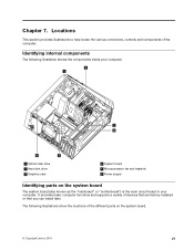
... The following illustrations show the locations of the different parts on the system board The system board (also known as the "mainboard" or "motherboard") is the main circuit board in your computer. 2 1 3 4 6 5 1 Optical disk drive 2 Hard disk drive 3 Graphics ...card 4 System board 5 Microprocessor fan and heatsink 6 Power supply Identifying parts on the system board. © Copyright Lenovo 2014 21 It provides basic computer functions and supports a variety of the computer. Locations This section provides illustrations to help locate the various connectors,...
... The following illustrations show the locations of the different parts on the system board The system board (also known as the "mainboard" or "motherboard") is the main circuit board in your computer. 2 1 3 4 6 5 1 Optical disk drive 2 Hard disk drive 3 Graphics ...card 4 System board 5 Microprocessor fan and heatsink 6 Power supply Identifying parts on the system board. © Copyright Lenovo 2014 21 It provides basic computer functions and supports a variety of the computer. Locations This section provides illustrations to help locate the various connectors,...
Lenovo K4 Series Hardware Maintenance Manual
Page 35
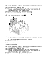
... includes power cords, input/output (I /O) cables, and any media (disks, CDs, DVDs, or memory cards) from the connector on the motherboard. Step 2. Step 4. Step 7. Disconnect all attached devices. Line up the holes on the new power supply with mounting holes on...off the computer and all power cords from electrical outlets. Step 1. Step 4. Remove any other cables that are connected to the connectors on the motherboard. Remove the computer cover. Replacing the microprocessor fan To replace the microprocessor fan: Step 1. Refer to the computer. This includes power cords, ...
... includes power cords, input/output (I /O) cables, and any media (disks, CDs, DVDs, or memory cards) from the connector on the motherboard. Step 2. Step 4. Step 7. Disconnect all attached devices. Line up the holes on the new power supply with mounting holes on...off the computer and all power cords from electrical outlets. Step 1. Step 4. Remove any other cables that are connected to the connectors on the motherboard. Remove the computer cover. Replacing the microprocessor fan To replace the microprocessor fan: Step 1. Refer to the computer. This includes power cords, ...

Lenovo K4 Series Hardware Maintenance Manual
Page 36
... heat-sink Note: For this procedure, it to remove it. Step 2. Step 4. Remove the computer cover. Remove the 4 screws that are connected to the motherboard. 32 Lenovo K4 SeriesHardware Maintenance Manual Step 7. b. Step 8. Step 3. Remove any other cables that secure the heat-sink to the computer. Connect the microprocessor fan power cable...
... heat-sink Note: For this procedure, it to remove it. Step 2. Step 4. Remove the computer cover. Remove the 4 screws that are connected to the motherboard. 32 Lenovo K4 SeriesHardware Maintenance Manual Step 7. b. Step 8. Step 3. Remove any other cables that secure the heat-sink to the computer. Connect the microprocessor fan power cable...
Lenovo K4 Series Hardware Maintenance Manual
Page 37
...the heat-sink. Reattach the computer cover. Remove the microprocessor fan. Reattach the microprocessor fan to remove it with mounting holes on the motherboard. Step 5. Unplug all power cords from the drives, shut down the operating system, and turn off the computer and all cables attached... to the connector on the motherboard and secure it . Remove the computer cover. Lift up the screws on the new heat-sink with the 4 screws. Step 4. Disconnect...
...the heat-sink. Reattach the computer cover. Remove the microprocessor fan. Reattach the microprocessor fan to remove it with mounting holes on the motherboard. Step 5. Unplug all power cords from the drives, shut down the operating system, and turn off the computer and all cables attached... to the connector on the motherboard and secure it . Remove the computer cover. Lift up the screws on the new heat-sink with the 4 screws. Step 4. Disconnect...

Lenovo K4 Series Hardware Maintenance Manual
Page 39
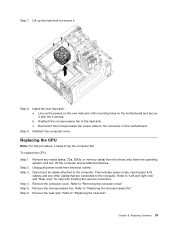
... the microprocessor so that the notches on the microprocessor are aligned with your fingers, remove the protective cover 1 that protects the gold contacts on the motherboard. Step 13. Chapter 8. Holding the sides of the microprocessor. Holding the sides of grease on the grease syringe). Replacing the Wi-Fi card Note: For...
... the microprocessor so that the notches on the microprocessor are aligned with your fingers, remove the protective cover 1 that protects the gold contacts on the motherboard. Step 13. Chapter 8. Holding the sides of the microprocessor. Holding the sides of grease on the grease syringe). Replacing the Wi-Fi card Note: For...
Lenovo K4 Series Hardware Maintenance Manual
Page 40
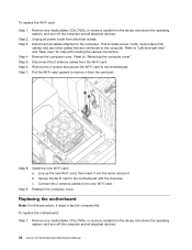
...memory cards) from the drives, shut down the operating system, and turn off the computer and all attached devices. Refer to the motherboard with locating the various connectors. Disconnect the 2 antenna cables from the drives, shut down the operating system, and turn off the computer... and all attached devices. 36 Lenovo K4 SeriesHardware Maintenance Manual Pull the Wi-Fi card upward to remove it helps to the motherboard. Step 8. Step 9. Replacing the motherboard Note: For this procedure, it from electrical outlets. Remove any other ...
...memory cards) from the drives, shut down the operating system, and turn off the computer and all attached devices. Refer to the motherboard with locating the various connectors. Disconnect the 2 antenna cables from the drives, shut down the operating system, and turn off the computer... and all attached devices. 36 Lenovo K4 SeriesHardware Maintenance Manual Pull the Wi-Fi card upward to remove it helps to the motherboard. Step 8. Step 9. Replacing the motherboard Note: For this procedure, it from electrical outlets. Remove any other ...
Lenovo K4 Series Hardware Maintenance Manual
Page 41
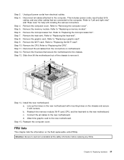
... cover". Disconnect the all cables attached to the computer. Step 15. FRU lists This chapter lists the information on the new motherboard with locating the various connectors. Disconnect all cables from electrical outlets. Refer to "Replacing the heat-sink". Step 12. c. ... graphic card". Attention: Be sure to read and understand all the safety information before replacing any other cables that secure the motherboard to the new motherboard. Step 2. Step 3. This includes power cords, input/output (I/O) cables, and any FRUs. Step 6. Step 7. Remove ...
... cover". Disconnect the all cables attached to the computer. Step 15. FRU lists This chapter lists the information on the new motherboard with locating the various connectors. Disconnect all cables from electrical outlets. Refer to "Replacing the heat-sink". Step 12. c. ... graphic card". Attention: Be sure to read and understand all the safety information before replacing any other cables that secure the motherboard to the new motherboard. Step 2. Step 3. This includes power cords, input/output (I/O) cables, and any FRUs. Step 6. Step 7. Remove ...


