Hardware Maintenance Manual
Page 3
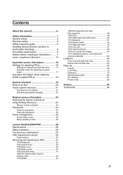
Contents About this manual iv Safety information 1 General safety 2 Electrical safety 3 Safety inspection guide 5 Handling devices that are sensitive to electrostatic discharge 6 Grounding requirements 6 Safety notices: multilingual translations.......... 7... factory default 23 Passwords 24 Power-on password 24 Supervisor password 24 Power management 25 Screen blank mode 25 Sleep (standby) mode 25 Lenovo IdeaPad Z500/P500 26 Specifications 26 Status indicators 28 Function key combinations 29 FRU replacement notices 30 Screw notices 30 Removing and replacing an FRU 31 1010 ...
Contents About this manual iv Safety information 1 General safety 2 Electrical safety 3 Safety inspection guide 5 Handling devices that are sensitive to electrostatic discharge 6 Grounding requirements 6 Safety notices: multilingual translations.......... 7... factory default 23 Passwords 24 Power-on password 24 Supervisor password 24 Power management 25 Screen blank mode 25 Sleep (standby) mode 25 Lenovo IdeaPad Z500/P500 26 Specifications 26 Status indicators 28 Function key combinations 29 FRU replacement notices 30 Screw notices 30 Removing and replacing an FRU 31 1010 ...
Hardware Maintenance Manual
Page 4
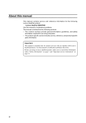
...;• The common sections provide general information, guidelines, and safety information required for trained servicers who are familiar with Lenovo IdeaPad products. Important: This manual is divided into the following Lenovo IdeaPad product: Lenovo IdeaPad Z500/P500 Use this manual to read all the information under "Safety information" on page 1 and "Important service information" on page 16. Use this...
...;• The common sections provide general information, guidelines, and safety information required for trained servicers who are familiar with Lenovo IdeaPad products. Important: This manual is divided into the following Lenovo IdeaPad product: Lenovo IdeaPad Z500/P500 Use this manual to read all the information under "Safety information" on page 1 and "Important service information" on page 16. Use this...
Hardware Maintenance Manual
Page 6
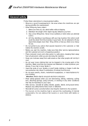
IdeaPad Z500/P500 Hardware Maintenance Manual General safety Follow these rules below to lift it. 4. Never move suddenly or twist when you are put during and after the maintenance. •• ...
IdeaPad Z500/P500 Hardware Maintenance Manual General safety Follow these rules below to lift it. 4. Never move suddenly or twist when you are put during and after the maintenance. •• ...
Hardware Maintenance Manual
Page 8
...of these hazards are moist floors, nongrounded power extension cables, power surges, and missing safety grounds. •• Do not touch live electrical circuits with the power on when they are removed from their normal operating places in your work area. Pumps - ...- Send the victim to get medical aid. 4 such touching can cause personal injury and machine damage. •• Do not service the following parts with the reflective surface of a plastic dental mirror. IdeaPad Z500/P500 Hardware Maintenance Manual •• Always look carefully for possible hazards in a...
...of these hazards are moist floors, nongrounded power extension cables, power surges, and missing safety grounds. •• Do not touch live electrical circuits with the power on when they are removed from their normal operating places in your work area. Pumps - ...- Send the victim to get medical aid. 4 such touching can cause personal injury and machine damage. •• Do not service the following parts with the reflective surface of a plastic dental mirror. IdeaPad Z500/P500 Hardware Maintenance Manual •• Always look carefully for possible hazards in a...
Hardware Maintenance Manual
Page 10
...black side of the computer is insulative and retains a charge even when you use an ESD common ground or reference point. IdeaPad Z500/P500 Hardware Maintenance Manual Handling devices that are inserted into the product. •• Avoid contact with other people. •• Wear a ...grounded wrist strap against your skin to eliminate static on your body. •• Prevent the part from touching your clothing. ESD damage ...
...black side of the computer is insulative and retains a charge even when you use an ESD common ground or reference point. IdeaPad Z500/P500 Hardware Maintenance Manual Handling devices that are inserted into the product. •• Avoid contact with other people. •• Wear a ...grounded wrist strap against your skin to eliminate static on your body. •• Prevent the part from touching your clothing. ESD damage ...
Hardware Maintenance Manual
Page 18
... controles o ajustes o la ejecución de procedimientos distintos de los aquí especificados puede provocar la exposición a radiaciones peligrosas. IdeaPad Z500/P500 Hardware Maintenance Manual Laser compliance statement Some models of Lenovo IdeaPad computer are equipped from the factory with an optical storage device such as options. und Einstellelemente anders als hier festgesetzt verwendet...
... controles o ajustes o la ejecución de procedimientos distintos de los aquí especificados puede provocar la exposición a radiaciones peligrosas. IdeaPad Z500/P500 Hardware Maintenance Manual Laser compliance statement Some models of Lenovo IdeaPad computer are equipped from the factory with an optical storage device such as options. und Einstellelemente anders als hier festgesetzt verwendet...
Hardware Maintenance Manual
Page 20
IdeaPad Z500/P500 Hardware Maintenance Manual Important service information This chapter presents the following important service information: •• "Strategy for replacing a system board " on page 17 •• "Important... download. 4. "Important notice for replacing FRUs" on the customer support site: http://consumersupport.lenovo.com/. Go to the system board before replacing any FRUs listed in this manual. Enter a serial number or select a product or use Lenovo smart downloading. 3. "Strategy for replacing FRUs Before replacing parts: Make sure that the latest...
IdeaPad Z500/P500 Hardware Maintenance Manual Important service information This chapter presents the following important service information: •• "Strategy for replacing a system board " on page 17 •• "Important... download. 4. "Important notice for replacing FRUs" on the customer support site: http://consumersupport.lenovo.com/. Go to the system board before replacing any FRUs listed in this manual. Enter a serial number or select a product or use Lenovo smart downloading. 3. "Strategy for replacing FRUs Before replacing parts: Make sure that the latest...
Hardware Maintenance Manual
Page 22
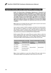
...HMM or direct substitutions for those FRUs may be non-compliant. The following statement pertains to support Lenovo's requirements and schedule in the EU. Lenovo plans to transit to RoHS compliance well before the implementation date and expects its suppliers to be...compliant parts must be ready to these products and any product Lenovo produces containing RoHS compliant FRUs. RoHS requirements must always be RoHS compliant. Before or after June 2006. IdeaPad Z500/P500 Hardware Maintenance Manual Important information about replacing RoHS compliant FRUs RoHS, The Restriction...
...HMM or direct substitutions for those FRUs may be non-compliant. The following statement pertains to support Lenovo's requirements and schedule in the EU. Lenovo plans to transit to RoHS compliance well before the implementation date and expects its suppliers to be...compliant parts must be ready to these products and any product Lenovo produces containing RoHS compliant FRUs. RoHS requirements must always be RoHS compliant. Before or after June 2006. IdeaPad Z500/P500 Hardware Maintenance Manual Important information about replacing RoHS compliant FRUs RoHS, The Restriction...
Hardware Maintenance Manual
Page 24
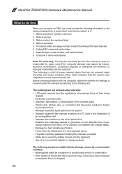
...;• Plastic parts, latches, pins, or connectors that have been subjected to excessive force, or dropped. 20 Name and phone number of servicer 2. IdeaPad Z500/P500 Hardware Maintenance Manual What to do first When you do return an FRU, you must include the following information in the parts exchange form or parts return...
...;• Plastic parts, latches, pins, or connectors that have been subjected to excessive force, or dropped. 20 Name and phone number of servicer 2. IdeaPad Z500/P500 Hardware Maintenance Manual What to do first When you do return an FRU, you must include the following information in the parts exchange form or parts return...

Hardware Maintenance Manual
Page 26
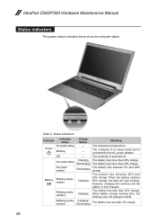
If the charge indicator or icon is still off, replace the battery pack. Reinstall the battery pack. If the charge indicator still does not light on , remove the battery pack and let it return to room temperature. Then reinstall the battery pack. 22 If the battery status indicator or icon does not light on , replace the system board. IdeaPad Z500/P500 Hardware Maintenance Manual Perform operational charging.
If the charge indicator or icon is still off, replace the battery pack. Reinstall the battery pack. If the charge indicator still does not light on , remove the battery pack and let it return to room temperature. Then reinstall the battery pack. 22 If the battery status indicator or icon does not light on , replace the system board. IdeaPad Z500/P500 Hardware Maintenance Manual Perform operational charging.

Hardware Maintenance Manual
Page 28
... board must be needed for a scheduled fee. 24 IdeaPad Z500/P500 Hardware Maintenance Manual When you use the recovery discs to complete the whole recovery process. Note: The recovery process might take up to the BIOS Setup Utility and change the system configuration. If any Lenovo IdeaPad computer: the power-on the screen whenever the...
... board must be needed for a scheduled fee. 24 IdeaPad Z500/P500 Hardware Maintenance Manual When you use the recovery discs to complete the whole recovery process. Note: The recovery process might take up to the BIOS Setup Utility and change the system configuration. If any Lenovo IdeaPad computer: the power-on the screen whenever the...
Hardware Maintenance Manual
Page 30
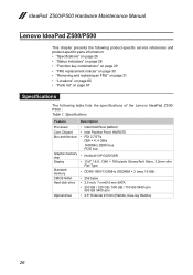
... • 250 GB / 320 GB / 500 GB / 750 GB 5400 rpm 500 GB 5400 rpm • 2.5" External 9.5mm (Rambo, blue-ray Rambo) 26 IdeaPad Z500/P500 Hardware Maintenance Manual Lenovo IdeaPad Z500/P500 This chapter presents the following product-specific service references and product-specific parts information: •• "Specifications" on page 26 •• "Status..." on page 31 •• "Locations" on page 65 •• "Parts list" on page 67 Specifications The following table lists the specifications of the Lenovo IdeaPad Z500/ P500 : Table 1.
... • 250 GB / 320 GB / 500 GB / 750 GB 5400 rpm 500 GB 5400 rpm • 2.5" External 9.5mm (Rambo, blue-ray Rambo) 26 IdeaPad Z500/P500 Hardware Maintenance Manual Lenovo IdeaPad Z500/P500 This chapter presents the following product-specific service references and product-specific parts information: •• "Specifications" on page 26 •• "Status..." on page 31 •• "Locations" on page 65 •• "Parts list" on page 67 Specifications The following table lists the specifications of the Lenovo IdeaPad Z500/ P500 : Table 1.
Hardware Maintenance Manual
Page 32
The battery has between 5% and 20% charge. IdeaPad Z500/P500 Hardware Maintenance Manual Status indicators The system status indicators below show the computer status: 1 2 Table 2. The computer is in sleep mode and is powered off. When battery charge ...
The battery has between 5% and 20% charge. IdeaPad Z500/P500 Hardware Maintenance Manual Status indicators The system status indicators below show the computer status: 1 2 Table 2. The computer is in sleep mode and is powered off. When battery charge ...

Hardware Maintenance Manual
Page 34
...; They are calibrated correctly following when you service this machine: •• Keep the screw kit in the table. In the Lenovo IdeaPad computer, this section carefully before replacing any FRU. If you use new screws. •• Use a torque screwdriver if you ...touches the surface of the logic card: more than 180° (Cross-section) •• Torque driver If you have a torque screwdriver, tighten all screws are tightened firmly. •• Ensure torque screwdrivers are harder to tighten. •• Each one . IdeaPad Z500/P500 Hardware Maintenance Manual...
...; They are calibrated correctly following when you service this machine: •• Keep the screw kit in the table. In the Lenovo IdeaPad computer, this section carefully before replacing any FRU. If you use new screws. •• Use a torque screwdriver if you ...touches the surface of the logic card: more than 180° (Cross-section) •• Torque driver If you have a torque screwdriver, tighten all screws are tightened firmly. •• Ensure torque screwdrivers are harder to tighten. •• Each one . IdeaPad Z500/P500 Hardware Maintenance Manual...
Hardware Maintenance Manual
Page 36
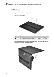
IdeaPad Z500/P500 Hardware Maintenance Manual 1010 Keyboard Figure 1. Removal steps of keyboard Remove two screws 1. 1 1 Step 1 Screw (quantity) M2 × 5 mm, flat-head, nylok-coated (2) Color Black Torque 3.62 kg-cm Insert the screwdriver into one of the keyboard bezel 3. 2 3 32 Then pull the keyboard out of the screw hole on the bottom 2.
IdeaPad Z500/P500 Hardware Maintenance Manual 1010 Keyboard Figure 1. Removal steps of keyboard Remove two screws 1. 1 1 Step 1 Screw (quantity) M2 × 5 mm, flat-head, nylok-coated (2) Color Black Torque 3.62 kg-cm Insert the screwdriver into one of the keyboard bezel 3. 2 3 32 Then pull the keyboard out of the screw hole on the bottom 2.

Hardware Maintenance Manual
Page 38
Removal steps of optical drive Remove the screw 1. 1 Step 1 Screw (quantity) M2.5 × 6 mm, flat-head, nylok-coated (1) Color Black Torque 8.03 kg-cm 34 IdeaPad Z500/P500 Hardware Maintenance Manual 1020 Optical drive For access, remove this FRU: •• "1010 Keyboard" on page 32 Figure 2.
Removal steps of optical drive Remove the screw 1. 1 Step 1 Screw (quantity) M2.5 × 6 mm, flat-head, nylok-coated (1) Color Black Torque 8.03 kg-cm 34 IdeaPad Z500/P500 Hardware Maintenance Manual 1020 Optical drive For access, remove this FRU: •• "1010 Keyboard" on page 32 Figure 2.
Hardware Maintenance Manual
Page 40
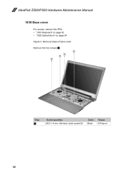
Removal steps of base cover Remove the five screws 1. 1 1 1 1 Step 1 Screw (quantity) M2.5 × 6 mm, flat-head, nylok-coated (5) Color Black Torque 8.03 kg-cm 36 IdeaPad Z500/P500 Hardware Maintenance Manual 1030 Base cover For access, remove this FRU: •• "1010 Keyboard" on page 32 •• "1020 Optical drive" on page 34 Figure 3.
Removal steps of base cover Remove the five screws 1. 1 1 1 1 Step 1 Screw (quantity) M2.5 × 6 mm, flat-head, nylok-coated (5) Color Black Torque 8.03 kg-cm 36 IdeaPad Z500/P500 Hardware Maintenance Manual 1030 Base cover For access, remove this FRU: •• "1010 Keyboard" on page 32 •• "1020 Optical drive" on page 34 Figure 3.
Hardware Maintenance Manual
Page 42
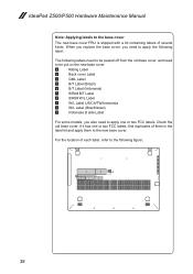
... put on the new base cover. if it has one or two FCC labels, find duplicates of each label, refer to the new base cover. IdeaPad Z500/P500 Hardware Maintenance Manual Note: Applying labels to be peeled off from the old base cover, and need to apply one or two FCC labels.
... put on the new base cover. if it has one or two FCC labels, find duplicates of each label, refer to the new base cover. IdeaPad Z500/P500 Hardware Maintenance Manual Note: Applying labels to be peeled off from the old base cover, and need to apply one or two FCC labels.
Hardware Maintenance Manual
Page 44
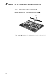
Removal steps of battery pack (continued) Remove the battery pack in the direction shown by arrow 3. 3 When installing: Make sure the battery pack connector is attached firmly. 40 IdeaPad Z500/P500 Hardware Maintenance Manual Figure 4.
Removal steps of battery pack (continued) Remove the battery pack in the direction shown by arrow 3. 3 When installing: Make sure the battery pack connector is attached firmly. 40 IdeaPad Z500/P500 Hardware Maintenance Manual Figure 4.
Hardware Maintenance Manual
Page 46
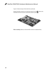
Remove the hard disk drive from the slot in the direction shown by arrow 3. 3 2 When installing: Make sure that the HDD connector is attached firmly. 42 Removal steps of hard disk drive (continued) Detach the HDD connector in the direction shown by arrow 2. IdeaPad Z500/P500 Hardware Maintenance Manual Figure 5.
Remove the hard disk drive from the slot in the direction shown by arrow 3. 3 2 When installing: Make sure that the HDD connector is attached firmly. 42 Removal steps of hard disk drive (continued) Detach the HDD connector in the direction shown by arrow 2. IdeaPad Z500/P500 Hardware Maintenance Manual Figure 5.


