User Guide
Page 4
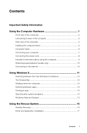
... the computer 2 Left and right views of the computer 3 Rear view of the computer 4 Installing the computer stand 5 Computer stand 6 Connecting your computer 7 Connecting the power cord 8 Important information about using the computer 9 Wired keyboard (selected models only 10 Connecting to the Internet 10 Using Windows 8 11 Switching between the main Windows...
... the computer 2 Left and right views of the computer 3 Rear view of the computer 4 Installing the computer stand 5 Computer stand 6 Connecting your computer 7 Connecting the power cord 8 Important information about using the computer 9 Wired keyboard (selected models only 10 Connecting to the Internet 10 Using Windows 8 11 Switching between the main Windows...

User Guide
Page 13
Connecting the power cord 8 User Guide
Connecting the power cord 8 User Guide

User Guide
Page 36
Unplug all power cords from scratches or other cables that are connected to the Support Web site at: http://support.lenovo.com Note: Use only parts provided by Lenovo. Lenovo recommends that you use a blanket, towel, or other soft cloth to "Left and right views" and "Rear view...a flat, stable surface. Replacing hardware Attention: Do not remove the computer cover or attempt any repairs before removing the cover. This includes power cords, input/output (I/O) cables, and any media (disks, CDs, or memory cards) from the computer. 3. General information Pre-disassembly instructions ...
Unplug all power cords from scratches or other cables that are connected to the Support Web site at: http://support.lenovo.com Note: Use only parts provided by Lenovo. Lenovo recommends that you use a blanket, towel, or other soft cloth to "Left and right views" and "Rear view...a flat, stable surface. Replacing hardware Attention: Do not remove the computer cover or attempt any repairs before removing the cover. This includes power cords, input/output (I/O) cables, and any media (disks, CDs, or memory cards) from the computer. 3. General information Pre-disassembly instructions ...
User Guide
Page 37
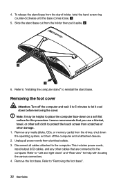
... foot base". 32 User Guide Refer to place the computer face-down before removing the cover. Unplug all cables attached to the computer. Disconnect all power cords from the holder then put it cool down on a soft flat surface for help with locating the various connectors. 4. This includes... base comes loose. 5. Refer to "Installing the computer stand" to protect the touch screen from scratches or other soft cloth to reinstall the stand base. Lenovo recommends that are connected to the computer. Slide the stand base out from electrical outlets. 3. Remove the foot base. 4.
... foot base". 32 User Guide Refer to place the computer face-down before removing the cover. Unplug all cables attached to the computer. Disconnect all power cords from the holder then put it cool down on a soft flat surface for help with locating the various connectors. 4. This includes... base comes loose. 5. Refer to "Installing the computer stand" to protect the touch screen from scratches or other soft cloth to reinstall the stand base. Lenovo recommends that are connected to the computer. Slide the stand base out from electrical outlets. 3. Remove the foot base. 4.

User Guide
Page 38
... the foot cover". Remove any other cables that you use a blanket, towel, or other damage. 1. To reattach the foot cover: a. Lenovo recommends that are connected to the computer. This includes power cords, input/output (I/O) cables, and any media (disks, CDs, or memory cards) from the drives, shut down the operating system, and turn...
... the foot cover". Remove any other cables that you use a blanket, towel, or other damage. 1. To reattach the foot cover: a. Lenovo recommends that are connected to the computer. This includes power cords, input/output (I/O) cables, and any media (disks, CDs, or memory cards) from the drives, shut down the operating system, and turn...

User Guide
Page 39
... devices. 2. Reattach the foot cover and stand base. Lenovo recommends that are connected to "Left and right views" and "Rear view" for this procedure. Refer to the computer. Remove any other damage. 1. Note: It may be removed using the same procedure. 7. This includes power cords, input/output (I/O) cables, and any media (disks, CDs...
... devices. 2. Reattach the foot cover and stand base. Lenovo recommends that are connected to "Left and right views" and "Rear view" for this procedure. Refer to the computer. Remove any other damage. 1. Note: It may be removed using the same procedure. 7. This includes power cords, input/output (I/O) cables, and any media (disks, CDs...
User Guide
Page 41
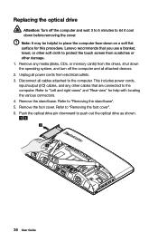
... stand base". 5. Refer to the computer. Remove the stand base. Refer to push out the optical drive as shown. 36 User Guide This includes power cords, input/output (I/O) cables, and any media (disks, CDs, or memory cards) from the drives, shut down the operating system, and turn off ...the computer and wait 3 to 5 minutes to the computer. Lenovo recommends that are connected to let it cool down on a soft flat surface for help with locating the various connectors. 4. Remove the foot cover. ...
... stand base". 5. Refer to the computer. Remove the stand base. Refer to push out the optical drive as shown. 36 User Guide This includes power cords, input/output (I/O) cables, and any media (disks, CDs, or memory cards) from the drives, shut down the operating system, and turn off ...the computer and wait 3 to 5 minutes to the computer. Lenovo recommends that are connected to let it cool down on a soft flat surface for help with locating the various connectors. 4. Remove the foot cover. ...

User Guide
Page 43
To install the new optical drive: a. c. Disconnect the adapter cable from the computer , then unplug the power cord from the drives, shut down the operating system, and turn off the computer and wait 3 to 5 minutes to let it cool down before removing the ...
To install the new optical drive: a. c. Disconnect the adapter cable from the computer , then unplug the power cord from the drives, shut down the operating system, and turn off the computer and wait 3 to 5 minutes to let it cool down before removing the ...

User Guide
Page 45
... cards) from electrical outlets. 3. Refer to "Side view of the computer" and "Rear view of the computer. Locate the connector for the keyboard. Unplug all power cords from the drives, shut down the computer, and turn off all attached devices. 2. Disconnect the defective keyboard cable from the computer and connect the new...
... cards) from electrical outlets. 3. Refer to "Side view of the computer" and "Rear view of the computer. Locate the connector for the keyboard. Unplug all power cords from the drives, shut down the computer, and turn off all attached devices. 2. Disconnect the defective keyboard cable from the computer and connect the new...


