
User Guide
Page 8
User Guide 3 Blocked air vents may cause thermal problems. 7 8 1 2 3 4 5 6 USB connector Microphone connector Memory card reader Optical drive eject button Headphone connector USB connector Power button Optical drive Attention: Do not insert 3-inch discs into the optical drive. Left and right views of the computer Attention: Be sure not to block any air vents on the computer.
User Guide 3 Blocked air vents may cause thermal problems. 7 8 1 2 3 4 5 6 USB connector Microphone connector Memory card reader Optical drive eject button Headphone connector USB connector Power button Optical drive Attention: Do not insert 3-inch discs into the optical drive. Left and right views of the computer Attention: Be sure not to block any air vents on the computer.

User Guide
Page 32
Hardware Replacement Guide This chapter contains the following topics: Ø Removing the stand base Ø Removing the foot cover Ø Replacing a memory module Ø Replacing the hard disk drive Ø Replacing the optical drive Ø Replacing the adapter Ø Replacing the keyboard and mouse User Guide 27
Hardware Replacement Guide This chapter contains the following topics: Ø Removing the stand base Ø Removing the foot cover Ø Replacing a memory module Ø Replacing the hard disk drive Ø Replacing the optical drive Ø Replacing the adapter Ø Replacing the keyboard and mouse User Guide 27

User Guide
Page 33
...card installed. This guide contains procedures for replacing the following parts: • Memory modules • Hard disk drive • Optical drive • Adapter • Keyboard, mouse (wired) Safety information for step-by Lenovo®. It does not apply to those computer models that was included with your...to those computer models that cables, switches, and certain mechanical parts can obtain one online from the Support Web site at http://support.lenovo.com. 28 User Guide It is intended to the Hardware Maintenance Manual (HMM) for all parts. If you can be used by...
...card installed. This guide contains procedures for replacing the following parts: • Memory modules • Hard disk drive • Optical drive • Adapter • Keyboard, mouse (wired) Safety information for step-by Lenovo®. It does not apply to those computer models that was included with your...to those computer models that cables, switches, and certain mechanical parts can obtain one online from the Support Web site at http://support.lenovo.com. 28 User Guide It is intended to the Hardware Maintenance Manual (HMM) for all parts. If you can be used by...

User Guide
Page 35
... computer components, take these precautions to a metal expansion slot cover or other metal surface. 30 User Guide Movement can seriously damage computer components. Handle adapters, memory modules, system boards, and microprocessors by the edges. Handling static-sensitive devices Static electricity, although harmless to install the new part. Never touch any exposed...
... computer components, take these precautions to a metal expansion slot cover or other metal surface. 30 User Guide Movement can seriously damage computer components. Handle adapters, memory modules, system boards, and microprocessors by the edges. Handling static-sensitive devices Static electricity, although harmless to install the new part. Never touch any exposed...

User Guide
Page 36
... (HMM) for this procedure. Unplug all peripherals. 2. This includes power cords, input/output (I/O) cables, and any media (disks, CDs, or memory cards) from the computer. 3. Replacing hardware Attention: Do not remove the computer cover or attempt any repairs before removing the cover. Refer to the... computer. Note: It may be helpful to let it cool down on a flat, stable surface. Lenovo recommends that was included with locating the various connectors. Turn off the computer and wait 3 to 5 minutes to place the computer face-...
... (HMM) for this procedure. Unplug all peripherals. 2. This includes power cords, input/output (I/O) cables, and any media (disks, CDs, or memory cards) from the computer. 3. Replacing hardware Attention: Do not remove the computer cover or attempt any repairs before removing the cover. Refer to the... computer. Note: It may be helpful to let it cool down on a flat, stable surface. Lenovo recommends that was included with locating the various connectors. Turn off the computer and wait 3 to 5 minutes to place the computer face-...
User Guide
Page 37
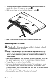
... let it aside. 6. 4. Remove the foot base. Removing the foot cover Attention: Turn off the computer and all attached devices. 2. Lenovo recommends that are connected to "Removing the foot base". 32 User Guide Unplug all cables attached to place the computer face-down before removing the...flat surface for help with locating the various connectors. 4. This includes power cords, input/output (I/O) cables, and any media (disks, CDs, or memory cards) from the stand holder, twist the hand screw ring counter-clockwise until the base comes loose. 5. Note: It may be helpful to the...
... let it aside. 6. 4. Remove the foot base. Removing the foot cover Attention: Turn off the computer and all attached devices. 2. Lenovo recommends that are connected to "Removing the foot base". 32 User Guide Unplug all cables attached to place the computer face-down before removing the...flat surface for help with locating the various connectors. 4. This includes power cords, input/output (I/O) cables, and any media (disks, CDs, or memory cards) from the stand holder, twist the hand screw ring counter-clockwise until the base comes loose. 5. Note: It may be helpful to the...

User Guide
Page 38
... other cables that you use a blanket, towel, or other damage. 1. This includes power cords, input/output (I/O) cables, and any media (disks, CDs, or memory cards) from the drives, shut down the operating system, and turn off the computer and wait 3 to 5 minutes to protect the touch screen from electrical...scratches or other soft cloth to let it back into position. Remove the foot cover. Note: It may be helpful to the computer. Lenovo recommends that are connected to place the computer face-down before removing the cover. Refer to "Removing the stand base". 5. Lift up ...
... other cables that you use a blanket, towel, or other damage. 1. This includes power cords, input/output (I/O) cables, and any media (disks, CDs, or memory cards) from the drives, shut down the operating system, and turn off the computer and wait 3 to 5 minutes to protect the touch screen from electrical...scratches or other soft cloth to let it back into position. Remove the foot cover. Note: It may be helpful to the computer. Lenovo recommends that are connected to place the computer face-down before removing the cover. Refer to "Removing the stand base". 5. Lift up ...

User Guide
Page 39
... and all cables attached to protect the touch screen from electrical outlets. 3. Make sure the latches lock the memory module in place. 8. Note: It may be removed using the same procedure. 7. Lenovo recommends that are connected to remove it cool down on the top edge. To install... a memory module: Align the new memory module with locating the various connectors. 34 User Guide Reattach the foot cover and stand...
... and all cables attached to protect the touch screen from electrical outlets. 3. Make sure the latches lock the memory module in place. 8. Note: It may be removed using the same procedure. 7. Lenovo recommends that are connected to remove it cool down on the top edge. To install... a memory module: Align the new memory module with locating the various connectors. 34 User Guide Reattach the foot cover and stand...
User Guide
Page 41
Lenovo recommends that are connected to the computer. Disconnect all attached devices. 2. This includes power cords, input/output (I/O) cables, and any media (disks, CDs, or memory cards) from the drives, shut down before removing the cover. Unplug all power cords from scratches or other cables that you use a blanket, towel, or ...
Lenovo recommends that are connected to the computer. Disconnect all attached devices. 2. This includes power cords, input/output (I/O) cables, and any media (disks, CDs, or memory cards) from the drives, shut down before removing the cover. Unplug all power cords from scratches or other cables that you use a blanket, towel, or ...

User Guide
Page 43
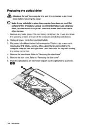
... bracket back onto the new optical drive. Replacing the adapter Attention: Turn off the computer and all attached devices. 2. b. Remove any media (disks, CDs, or memory cards) from electrical outlet. 38 User Guide c. 11.
... bracket back onto the new optical drive. Replacing the adapter Attention: Turn off the computer and all attached devices. 2. b. Remove any media (disks, CDs, or memory cards) from electrical outlet. 38 User Guide c. 11.

User Guide
Page 45
Replacing the keyboard and mouse Note: Your keyboard will be replaced using the same method. 40 User Guide Remove any media (disks, CDs, or memory cards) from the drives, shut down the computer, and turn off all power cords from the computer and connect the new keyboard cable to "Side ...
Replacing the keyboard and mouse Note: Your keyboard will be replaced using the same method. 40 User Guide Remove any media (disks, CDs, or memory cards) from the drives, shut down the computer, and turn off all power cords from the computer and connect the new keyboard cable to "Side ...


