
User Manual
Page 5
... 19 Passwords 20 Power management 22 Checkout guide 24 Testing the computer 24 Detecting system information with PC-Doctor . . 26 Power system checkout 26 Lenovo 3000 N100 and N200 . . . . . 29 Product overview 30 Specifications 30 Status indicators 33 FRU tests 34 Fn key combinations 35 Symptom...Intermittent problems 41 Undetermined problems 41 FRU replacement notices 42 Screw notices 42 Retaining serial numbers 42 Removing and replacing a FRU 45 1010 Battery pack 46 1020 Hard disk drive slot cover 47 1030 Hard disk drive 48 1040 PCI Express Mini Card for 802.11 a/b/g ...
... 19 Passwords 20 Power management 22 Checkout guide 24 Testing the computer 24 Detecting system information with PC-Doctor . . 26 Power system checkout 26 Lenovo 3000 N100 and N200 . . . . . 29 Product overview 30 Specifications 30 Status indicators 33 FRU tests 34 Fn key combinations 35 Symptom...Intermittent problems 41 Undetermined problems 41 FRU replacement notices 42 Screw notices 42 Retaining serial numbers 42 Removing and replacing a FRU 45 1010 Battery pack 46 1020 Hard disk drive slot cover 47 1030 Hard disk drive 48 1040 PCI Express Mini Card for 802.11 a/b/g ...

User Manual
Page 20
... strap against ESD damage by a certified electrician. 14 MT 0689, 0768, and 0769 v Use the black side of the ac plug on a double-insulated or battery-operated system, use have been certified (ISO 9000) as those listed below, to electrostatic discharge (ESD.) ESD damage can use of the electrical outlet can...
... strap against ESD damage by a certified electrician. 14 MT 0689, 0768, and 0769 v Use the black side of the ac plug on a double-insulated or battery-operated system, use have been certified (ISO 9000) as those listed below, to electrostatic discharge (ESD.) ESD damage can use of the electrical outlet can...
User Manual
Page 27
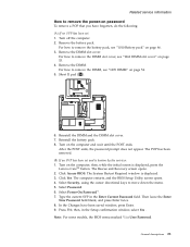
... current SVP in the Setup confirmation window, select Yes . Note: For some models, the BIOS menu marked *1 is displayed, press the Lenovo CareSM button. Remove the battery pack. For how to remove the DIMM slot cover, see "1070 DIMM" on page 54. 5. Turn on page 46. 3. Select ...Password. 6. In the Changes have forgotten, do the following: (A) If no SVP has been set and is displayed. 3. Press F10; Reinstall the battery pack. 8. Then leave the Enter New Password field blank, and press Enter twice. 8. Remove the DIMM. The Rescue and Recovery screen opens. 2. ...
... current SVP in the Setup confirmation window, select Yes . Note: For some models, the BIOS menu marked *1 is displayed, press the Lenovo CareSM button. Remove the battery pack. For how to remove the DIMM slot cover, see "1070 DIMM" on page 54. 5. Turn on page 46. 3. Select ...Password. 6. In the Changes have forgotten, do the following: (A) If no SVP has been set and is displayed. 3. Press F10; Reinstall the battery pack. 8. Then leave the Enter New Password field blank, and press Enter twice. 8. Remove the DIMM. The Rescue and Recovery screen opens. 2. ...

User Manual
Page 29
..., and system status is restored from the hard disk drive. General descriptions 23 Related service information v If the battery indicator blinks orange, indicating that the battery power is low. (Alternatively, if Hibernate when battery becomes low has been selected in the following event, the computer automatically returns from sleep (standby) mode and resumes...
..., and system status is restored from the hard disk drive. General descriptions 23 Related service information v If the battery indicator blinks orange, indicating that the battery power is low. (Alternatively, if Hibernate when battery becomes low has been selected in the following event, the computer automatically returns from sleep (standby) mode and resumes...
User Manual
Page 32
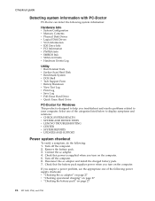
... product is supplied when you turn on the computer. Connect the ac adapter. 4. Disconnect the ac adapter and install the charged battery pack. 7. Check that power is designed to help you troubleshoot and resolve problems related to display symptoms and solutions: v CHECK ...SYSTEM HEALTH v SYSTEM AND DEVICE TESTS v LENOVO TROUBLESHOOTING v CENTER v SYSTEM REPORTS v UPDATES AND SUPPORT Power system checkout To verify a symptom, do the following power supply checkouts: v "...
... product is supplied when you turn on the computer. Connect the ac adapter. 4. Disconnect the ac adapter and install the charged battery pack. 7. Check that power is designed to help you troubleshoot and resolve problems related to display symptoms and solutions: v CHECK ...SYSTEM HEALTH v SYSTEM AND DEVICE TESTS v LENOVO TROUBLESHOOTING v CENTER v SYSTEM REPORTS v UPDATES AND SUPPORT Power system checkout To verify a symptom, do the following power supply checkouts: v "...

User Manual
Page 33
...v If the problem persists, go to the Power Meter icon in the computer. v If the computer does not charge during operation, use a discharged battery pack or a battery pack that less than 50% of the ac adapter for a moment (but do the following : 1. Note: Noise from the one you are here ...the computer fails only when the ac adapter is still not charged, go to 100% of the ac adapter cable. under this condition the battery pack can charge to ″Checking operational charging.″ To check the ac adapter, do the following : v Replace the system board. Perform operational...
...v If the problem persists, go to the Power Meter icon in the computer. v If the computer does not charge during operation, use a discharged battery pack or a battery pack that less than 50% of the ac adapter for a moment (but do the following : 1. Note: Noise from the one you are here ...the computer fails only when the ac adapter is still not charged, go to 100% of the ac adapter cable. under this condition the battery pack can charge to ″Checking operational charging.″ To check the ac adapter, do the following : v Replace the system board. Perform operational...

User Manual
Page 34
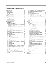
... the system board. 28 MT 0689, 0768, and 0769 To check the battery pack, do the following figure: 7(-) 6(-) 34 5 1(+) 2(+) Terminal 1 7 Voltage (V dc) + 0 to + 12.6 Ground (−) 3. Checkout guide Note: If the battery pack becomes hot, it . After it cools down, reinstall and recharge it... may not be 4 to charge. Remove the battery pack and measure the voltage between battery terminals 4 and 7. If the voltage is still less than +11.0 V dc, measure the resistance between battery terminals 1 (+) and 7 (−). Remove it from the computer and ...
... the system board. 28 MT 0689, 0768, and 0769 To check the battery pack, do the following figure: 7(-) 6(-) 34 5 1(+) 2(+) Terminal 1 7 Voltage (V dc) + 0 to + 12.6 Ground (−) 3. Checkout guide Note: If the battery pack becomes hot, it . After it cools down, reinstall and recharge it... may not be 4 to charge. Remove the battery pack and measure the voltage between battery terminals 4 and 7. If the voltage is still less than +11.0 V dc, measure the resistance between battery terminals 1 (+) and 7 (−). Remove it from the computer and ...
User Manual
Page 35
... number of the system unit 43 Retaining the UUID 43 Reading or writing the ECA information . . 43 Removing and replacing a FRU 45 1010 Battery pack 46 1020 Hard disk drive slot cover 47 1030 Hard disk drive 48 1040 PCI Express Mini Card for 802.11 a/b/g wireless LAN 49... assembly, and bottom cover assembly (D cover) for MT 0769 151 Miscellaneous parts 152 Common parts list 154 Tools 154 Notices 155 Trademarks 156 © Copyright Lenovo 2007 29 WSXGA+ TFT 134 Keyboard 136 Keyboard for MT 0689 and 0768 . . . . . 136 Keyboard for MT 0769 137 Recovery discs 138 Windows...
... number of the system unit 43 Retaining the UUID 43 Reading or writing the ECA information . . 43 Removing and replacing a FRU 45 1010 Battery pack 46 1020 Hard disk drive slot cover 47 1030 Hard disk drive 48 1040 PCI Express Mini Card for 802.11 a/b/g wireless LAN 49... assembly, and bottom cover assembly (D cover) for MT 0769 151 Miscellaneous parts 152 Common parts list 154 Tools 154 Notices 155 Trademarks 156 © Copyright Lenovo 2007 29 WSXGA+ TFT 134 Keyboard 136 Keyboard for MT 0689 and 0768 . . . . . 136 Keyboard for MT 0769 137 Recovery discs 138 Windows...

User Manual
Page 38
... Mini-PCI Express Adapter • Broadcom 802.11ag WLAN PCI-E Mini Card • Broadcom 802.11bg WLAN PCI-E Mini Card • Lenovo 11a/b/g/n Wireless LAN Mini-PCI Express Adapter • Intel Wireless WiFi Link 4965AGN PC Card slot for MT 0689 and • PC Card...8226; ExpressCard slot Bluetooth wireless (some models) • Bluetooth daughter card Modem • MDC-1.5, 56 kbps V.92 Touch pad Yes Battery • Li-ion battery (6 cells) 2.2 Ah • Li-ion battery (9 cells) 2.2 Ah AC adapter • 65-watt (20 V) slim type • 90-watt (20 V) type Preinstalled operating...
... Mini-PCI Express Adapter • Broadcom 802.11ag WLAN PCI-E Mini Card • Broadcom 802.11bg WLAN PCI-E Mini Card • Lenovo 11a/b/g/n Wireless LAN Mini-PCI Express Adapter • Intel Wireless WiFi Link 4965AGN PC Card slot for MT 0689 and • PC Card...8226; ExpressCard slot Bluetooth wireless (some models) • Bluetooth daughter card Modem • MDC-1.5, 56 kbps V.92 Touch pad Yes Battery • Li-ion battery (6 cells) 2.2 Ah • Li-ion battery (9 cells) 2.2 Ah AC adapter • 65-watt (20 V) slim type • 90-watt (20 V) type Preinstalled operating...

User Manual
Page 40
... --> Fixed Disks v Diagnostics --> Diskette Drives 1. If two DIMMs are installed, remove one , and run the test again. 3. Blinking green: The battery is charged between 0% to 20% of the capacity, and being charged. Interactive Tests --> Video 1. Diagnostics --> CPU/Coprocessor 2. Green: The computer is... green: The computer is entering sleep (standby) mode or hibernation mode, or is in suspend mode. Orange: The battery is operational. FRU System board LCD unit Keyboard Hard disk drive Diskette drive Memory Applicable test 1. Diagnostics --> Video Adapter 2. Product...
... --> Fixed Disks v Diagnostics --> Diskette Drives 1. If two DIMMs are installed, remove one , and run the test again. 3. Blinking green: The battery is charged between 0% to 20% of the capacity, and being charged. Interactive Tests --> Video 1. Diagnostics --> CPU/Coprocessor 2. Green: The computer is... green: The computer is entering sleep (standby) mode or hibernation mode, or is in suspend mode. Orange: The battery is operational. FRU System board LCD unit Keyboard Hard disk drive Diskette drive Memory Applicable test 1. Diagnostics --> Video Adapter 2. Product...
User Manual
Page 42
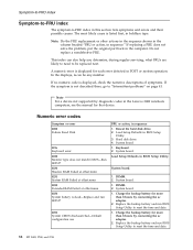
... run BIOS Setup Utility to reset the time and date. 1. System board. 1. DIMM. 2. Charge the backup battery for more than 8 hours by diagnostic codes in the Lenovo 3000 notebook computers, see the manual for each error detected in this section lists symptoms and errors and their possible...and date. 36 MT 0689, 0768, and 0769 Note For a device not supported by connecting the ac adapter. 2. DIMM. 2. Replace the backup battery and run SETUP 0251 System CMOS checksum bad-Default configuration use FRU or action, in boldface type. Hard disk drive. 4. Keyboard. 2. Note: Do...
... run BIOS Setup Utility to reset the time and date. 1. System board. 1. DIMM. 2. Charge the backup battery for more than 8 hours by diagnostic codes in the Lenovo 3000 notebook computers, see the manual for each error detected in this section lists symptoms and errors and their possible...and date. 36 MT 0689, 0768, and 0769 Note For a device not supported by connecting the ac adapter. 2. DIMM. 2. Replace the backup battery and run SETUP 0251 System CMOS checksum bad-Default configuration use FRU or action, in boldface type. Hard disk drive. 4. Keyboard. 2. Note: Do...

User Manual
Page 43
System board. 1. Charge the backup battery for more than 8 hours by connecting the ac adapter. 2. DIMM. 2. System board. 1. Lenovo 3000 N100 and N200 37 Default configuration used 02F4 EISA CMOS not writable 02F5 DMA test failed 02F6 Software NMI failed 02F7 Fail-safe timer... NMI failed Symptom-to-FRU index FRU or action, in BIOS Setup Utility. 2. Replace the backup battery and run BIOS Setup Utility...
System board. 1. Charge the backup battery for more than 8 hours by connecting the ac adapter. 2. DIMM. 2. System board. 1. Lenovo 3000 N100 and N200 37 Default configuration used 02F4 EISA CMOS not writable 02F5 DMA test failed 02F6 Software NMI failed 02F7 Fail-safe timer... NMI failed Symptom-to-FRU index FRU or action, in BIOS Setup Utility. 2. Replace the backup battery and run BIOS Setup Utility...
User Manual
Page 44
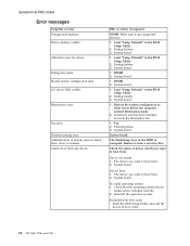
Failing bits: nnnn. Backup battery. 3. System board. 1. Backup battery. 3. System board. Device Error. 1. System board. Reinstall the operation system. v Enter the BIOS Setup Utility and add the device in the BIOS Setup Utility. ... device which you want to boot from . FRU or action, in the BIOS Setup Utility. 2. Fan. 2. I/O device IRQ conflict. Press to boot from . 2. Backup battery. 3. System board. 1. Load "Setup Defaults" in the HDD is installed correctly. 2. System board. The Predesktop Area in the BIOS Setup Utility. 2. Device address conflict....
Failing bits: nnnn. Backup battery. 3. System board. 1. Backup battery. 3. System board. Device Error. 1. System board. Reinstall the operation system. v Enter the BIOS Setup Utility and add the device in the BIOS Setup Utility. ... device which you want to boot from . FRU or action, in the BIOS Setup Utility. 2. Fan. 2. I/O device IRQ conflict. Press to boot from . 2. Backup battery. 3. System board. 1. Load "Setup Defaults" in the HDD is installed correctly. 2. System board. The Predesktop Area in the BIOS Setup Utility. 2. Device address conflict....
User Manual
Page 47
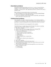
Run the diagnostic test for damage. Verify that all of causes that have no defects). Non-Lenovo 3000 devices b. External diskette drive or optical drive g. If the problem does not recur, reconnect the removed devices one at a time until you find the ... time of the failure is detected, do with a hardware defect, such as cosmic radiation, electrostatic discharge, or software errors. Turn off the computer. 2. LCD assembly Lenovo 3000 N100 and N200 41 FRU replacement should be due to a variety of the following : 1. System board...
Run the diagnostic test for damage. Verify that all of causes that have no defects). Non-Lenovo 3000 devices b. External diskette drive or optical drive g. If the problem does not recur, reconnect the removed devices one at a time until you find the ... time of the failure is detected, do with a hardware defect, such as cosmic radiation, electrostatic discharge, or software errors. Turn off the computer. 2. LCD assembly Lenovo 3000 N100 and N200 41 FRU replacement should be due to a variety of the following : 1. System board...
User Manual
Page 51
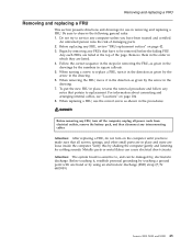
...replacing a FRU, use in place, reverse the removal procedure and follow any FRUs that all power cords from electrical outlets, remove the battery pack, and then disconnect any FRU, turn on the computer until you have been trained and certified. Attention: After replacing a FRU, ... of damaging parts. 2. Removing and replacing a FRU Removing and replacing a FRU This section presents directions and drawings for rattling sounds. Lenovo 3000 N100 and N200 45 Begin by , electrostatic discharge. Remove them in the order in the procedures. DANGER Before removing any interconnecting ...
...replacing a FRU, use in place, reverse the removal procedure and follow any FRUs that all power cords from electrical outlets, remove the battery pack, and then disconnect any FRU, turn on the computer until you have been trained and certified. Attention: After replacing a FRU, ... of damaging parts. 2. Removing and replacing a FRU Removing and replacing a FRU This section presents directions and drawings for rattling sounds. Lenovo 3000 N100 and N200 45 Begin by , electrostatic discharge. Remove them in the order in the procedures. DANGER Before removing any interconnecting ...

User Manual
Page 52
Removing and replacing a FRU 1010 Battery pack DANGER Use only the battery specified in the direction shown by arrow 3. 1 2 3 46 MT 0689, 0768, and 0769 Unlock the battery release lever 1 and holding the battery release lever in the unlocked position 2 , remove the battery pack in the parts list for your computer. Any other battery could ignite or explode.
Removing and replacing a FRU 1010 Battery pack DANGER Use only the battery specified in the direction shown by arrow 3. 1 2 3 46 MT 0689, 0768, and 0769 Unlock the battery release lever 1 and holding the battery release lever in the unlocked position 2 , remove the battery pack in the parts list for your computer. Any other battery could ignite or explode.

User Manual
Page 53
1020 Hard disk drive slot cover For access, remove this FRU: v "1010 Battery pack" on page 46 Removing and replacing a FRU 2 1 1 For MT 0689 and 0768 Step 1 Screw (quantity) M2.5 × 4 mm, flat-head, nylon-coated (2) For MT 0769 Step 1 Screw (quantity) M2.5 × 4 mm, pan-head, nylon-coated (2) Color Silver Torque 0.392 Nm (4 kgfcm) Color Silver Torque 0.392 Nm (4 kgfcm) Lenovo 3000 N100 and N200 47
1020 Hard disk drive slot cover For access, remove this FRU: v "1010 Battery pack" on page 46 Removing and replacing a FRU 2 1 1 For MT 0689 and 0768 Step 1 Screw (quantity) M2.5 × 4 mm, flat-head, nylon-coated (2) For MT 0769 Step 1 Screw (quantity) M2.5 × 4 mm, pan-head, nylon-coated (2) Color Silver Torque 0.392 Nm (4 kgfcm) Color Silver Torque 0.392 Nm (4 kgfcm) Lenovo 3000 N100 and N200 47

User Manual
Page 54
... data. The hard disk drive is sensitive to it if possible. v Never remove the drive while the system is operating or is in order: v "1010 Battery pack" on page 46 v "1020 Hard disk drive slot cover" on it . Removing and replacing a FRU 1030 Hard disk drive For access, remove these FRUs...
... data. The hard disk drive is sensitive to it if possible. v Never remove the drive while the system is operating or is in order: v "1010 Battery pack" on page 46 v "1020 Hard disk drive slot cover" on it . Removing and replacing a FRU 1030 Hard disk drive For access, remove these FRUs...

User Manual
Page 55
... the jacks by using the removal tool antenna RF connector (P/N: 08K7159) or pick the connectors with your fingers and gently unplug them in order: v "1010 Battery pack" on page 46 v "1020 Hard disk drive slot cover" on the card, and the black cable into the jack labeled AUX. (continued...) Lenovo 3000 N100 and N200 49 Removing and replacing a FRU 1040 PCI Express Mini Card for 802.11 a/b/g wireless LAN For access, remove these FRUs in ...
... the jacks by using the removal tool antenna RF connector (P/N: 08K7159) or pick the connectors with your fingers and gently unplug them in order: v "1010 Battery pack" on page 46 v "1020 Hard disk drive slot cover" on the card, and the black cable into the jack labeled AUX. (continued...) Lenovo 3000 N100 and N200 49 Removing and replacing a FRU 1040 PCI Express Mini Card for 802.11 a/b/g wireless LAN For access, remove these FRUs in ...

User Manual
Page 57
Removing and replacing a FRU 1050 PCI Express Mini Card for 802.11 a/b/g/n wireless LAN For access, remove these FRUs in order: v "1010 Battery pack" on page 46 v "1020 Hard disk drive slot cover" on the card, and the black cable (AUX) into the jack labeled card. When installing: ... removal tool antenna RF connector (P/N: 08K7159) or pick the connectors with your fingers and gently unplug them in direction of the arrow. on the (continued) Lenovo 3000 N100 and N200 51
Removing and replacing a FRU 1050 PCI Express Mini Card for 802.11 a/b/g/n wireless LAN For access, remove these FRUs in order: v "1010 Battery pack" on page 46 v "1020 Hard disk drive slot cover" on the card, and the black cable (AUX) into the jack labeled card. When installing: ... removal tool antenna RF connector (P/N: 08K7159) or pick the connectors with your fingers and gently unplug them in direction of the arrow. on the (continued) Lenovo 3000 N100 and N200 51


